US3554850A - Laminated floor covering and method of making same - Google Patents
Laminated floor covering and method of making same Download PDFInfo
- Publication number
- US3554850A US3554850A US676548A US3554850DA US3554850A US 3554850 A US3554850 A US 3554850A US 676548 A US676548 A US 676548A US 3554850D A US3554850D A US 3554850DA US 3554850 A US3554850 A US 3554850A
- Authority
- US
- United States
- Prior art keywords
- layers
- layer
- floor
- strips
- lowest
- Prior art date
- Legal status (The legal status is an assumption and is not a legal conclusion. Google has not performed a legal analysis and makes no representation as to the accuracy of the status listed.)
- Expired - Lifetime
Links
Images
Classifications
-
- E—FIXED CONSTRUCTIONS
- E04—BUILDING
- E04F—FINISHING WORK ON BUILDINGS, e.g. STAIRS, FLOORS
- E04F15/00—Flooring
- E04F15/02—Flooring or floor layers composed of a number of similar elements
- E04F15/022—Flooring consisting of parquetry tiles on a non-rollable sub-layer of other material, e.g. board, concrete, cork
-
- E—FIXED CONSTRUCTIONS
- E04—BUILDING
- E04F—FINISHING WORK ON BUILDINGS, e.g. STAIRS, FLOORS
- E04F15/00—Flooring
- E04F15/02—Flooring or floor layers composed of a number of similar elements
- E04F15/04—Flooring or floor layers composed of a number of similar elements only of wood or with a top layer of wood, e.g. with wooden or metal connecting members
- E04F15/041—Flooring or floor layers composed of a number of similar elements only of wood or with a top layer of wood, e.g. with wooden or metal connecting members with a top layer of wood in combination with a lower layer of other material
- E04F15/043—Flooring or floor layers composed of a number of similar elements only of wood or with a top layer of wood, e.g. with wooden or metal connecting members with a top layer of wood in combination with a lower layer of other material the lower layer being of organic plastic with or without reinforcements or filling materials
-
- E—FIXED CONSTRUCTIONS
- E04—BUILDING
- E04F—FINISHING WORK ON BUILDINGS, e.g. STAIRS, FLOORS
- E04F15/00—Flooring
- E04F15/02—Flooring or floor layers composed of a number of similar elements
- E04F15/04—Flooring or floor layers composed of a number of similar elements only of wood or with a top layer of wood, e.g. with wooden or metal connecting members
- E04F15/045—Layered panels only of wood
-
- Y—GENERAL TAGGING OF NEW TECHNOLOGICAL DEVELOPMENTS; GENERAL TAGGING OF CROSS-SECTIONAL TECHNOLOGIES SPANNING OVER SEVERAL SECTIONS OF THE IPC; TECHNICAL SUBJECTS COVERED BY FORMER USPC CROSS-REFERENCE ART COLLECTIONS [XRACs] AND DIGESTS
- Y10—TECHNICAL SUBJECTS COVERED BY FORMER USPC
- Y10T—TECHNICAL SUBJECTS COVERED BY FORMER US CLASSIFICATION
- Y10T156/00—Adhesive bonding and miscellaneous chemical manufacture
- Y10T156/10—Methods of surface bonding and/or assembly therefor
- Y10T156/1089—Methods of surface bonding and/or assembly therefor of discrete laminae to single face of additional lamina
-
- Y—GENERAL TAGGING OF NEW TECHNOLOGICAL DEVELOPMENTS; GENERAL TAGGING OF CROSS-SECTIONAL TECHNOLOGIES SPANNING OVER SEVERAL SECTIONS OF THE IPC; TECHNICAL SUBJECTS COVERED BY FORMER USPC CROSS-REFERENCE ART COLLECTIONS [XRACs] AND DIGESTS
- Y10—TECHNICAL SUBJECTS COVERED BY FORMER USPC
- Y10T—TECHNICAL SUBJECTS COVERED BY FORMER US CLASSIFICATION
- Y10T428/00—Stock material or miscellaneous articles
- Y10T428/16—Two dimensionally sectional layer
- Y10T428/163—Next to unitary web or sheet of equal or greater extent
-
- Y—GENERAL TAGGING OF NEW TECHNOLOGICAL DEVELOPMENTS; GENERAL TAGGING OF CROSS-SECTIONAL TECHNOLOGIES SPANNING OVER SEVERAL SECTIONS OF THE IPC; TECHNICAL SUBJECTS COVERED BY FORMER USPC CROSS-REFERENCE ART COLLECTIONS [XRACs] AND DIGESTS
- Y10—TECHNICAL SUBJECTS COVERED BY FORMER USPC
- Y10T—TECHNICAL SUBJECTS COVERED BY FORMER US CLASSIFICATION
- Y10T428/00—Stock material or miscellaneous articles
- Y10T428/24—Structurally defined web or sheet [e.g., overall dimension, etc.]
- Y10T428/24058—Structurally defined web or sheet [e.g., overall dimension, etc.] including grain, strips, or filamentary elements in respective layers or components in angular relation
- Y10T428/24066—Wood grain
Definitions
- a flooring element which comprises at least three layers; an upper layer which forms the floor surface, a lower layer which contacts the under floor and a middle layer; all layers being bonded by adhesives.
- Each of the lower and middle layers is composed of continuous strips which are parallel and spaced apart, preferably by a distance of two to three times the thickness of the element. The strips of the lowest and middle layers intersect at an angle of 90.
- the various layers are generally similar in horizontal dimensions, and all layers but the lowest are superimposed.
- the lowest layer is diagonally offset to provide a projection on two sides which preferably has a width which is at least to 8 times the element thickness.
- These elements may be assembled into a floor without the necessity of bonding to the floor by applying adhesive to the projections formed by the oifset lower layer, laying a second element adjacent the first to cover the extension of the first and applying pressure to the superimposed portions, as by tapping with a hammer.
- the invention concerns a floor covering consisting of at least three layers of thin and flexible frieze one above the other and fastened together by adhesives, the lowest being olfset in relation to the other two which coincide, and rabbets being left free between the separate elements of the middle and lowest layers.
- a floor covering of that kind is already known, which has, however, the disadvantage that the rabbets in the lowest layer run at right angles to the edge of the upper layers, with the result that no adequate coinciding with or covering of the rabbets of the middle layer is ensured when the sheets are placed together in the laying of the floor covering in the building.
- a further disadvantage of the known floor covering resides in the fact that the in dividual elements of the middle and the lowest layers are formed only partially as short strips which do not extend the full width, whereas other strips exhibit a square or rectangular shape, as a result of which no adequate lock effect is achieved, and also no adequate dimensional stability in a changeable climate or under damp conditions inside the building.
- a flooring element for parquet-type floors consisting of two layers of soft wood glued and locked together on to which is glued a hardwood walking surface, all the layers being locked in relation to one another by means of the boards of the middle layer which are displaced by something under 45 in relation to the grain of the walking surface and the supporting layer.
- Each board of that middle layer has, along each longer frontal side, a fixed spring protruding in relation to the walking layer and the supporting layer and along each of the other frontal sides a groove.
- edge straps are provided for the improvement of the locking effect.
- the object of the present invention is to eliminate these disadvantages and in particular to create a floor of the kind mentioned above which makes possible, among other things, very rapid laying without drying periods.
- the rabbets of the middle and the lowest layer intersect one another at an angle of the elements are, in a manner known per se, formed as strips; and those strips extend right through.
- Wood as is known, is liable to swell, and it alters its dimensions when dampness operates on it, and particularly when the floor is laid in new buildings which are still damp. Swelling and shrinkage are, however, avoided by locking.
- a further development of the invention envisages that the width of the rabbets is two to three times as great as the thickness of the floor elements.
- the projecting parts of the layers are provided with an adhesive which is permanently adhesive.
- This does not take place on site inside the building, but in the factory where the floor covering is made, so that the manipulation of adhesive in the building is entirely done away with.
- a process for the laying of the flooring of the invention in which the individual prefabricated plates or sheets are fastened to one another merely by pressure on the projecting parts already mentioned.
- the pressure in question can be applied by knocking with a hammer.
- a hammer and a saw for adapting the flooring to the size of the room, there being no need for any special measures for attachment to the under-floor.
- Further appliances such as a sanding machine, sealing agents and the like are no longer necessary in the building.
- connection to the underfloor is avoided, an effect which is called floating floorlaying.
- This makes an underlay of sound-, heator moistore-insulation possible.
- laying of the floor on under-floors which are not fully dried out is possible, which was out of the question previously. It is no longer necessary to observe any drying periods after the laying and the sealing.
- connection of the floor elements to one another over an extensive surface achieved by means of the pressing according to the invention gives an exactly-defined level for the upper edge of any given plate or sheet in relation to the upper edge of the neighbouring plate or sheet, and accordingly offers a ridge-free and rabbct-free connection which is independent of unevennesses in the under-floor.
- the invention also envisages a process for the manufacture of the floor covering according to the invention. According to that process, after the two upper layers have been stuck together, the plate so formed is processed and sanded to the exact thickness required, after which the edges are dressed and the surface is sealed. The intermediate product thus obtained is stuck on to the underlayer, the projecting parts already mentioned forming a projection of thickness at least five to eight times the total thickness of the plates.
- the adhesive already mentioned is applied over the whole surface of every plate so that an additional application of adhesive to the projecting parts in a separate operation is not necessary. This adhesive is very long-lasting and can be used even after being kept for a long time at the building site, the pressure, as already mentioned, being simply applied from above.
- the plate is pre-finished in such a way that the extremely simple laying of the floor on site as already mentioned can be carried out without anyone having to put up with any disadvantages.
- the frontal edges of the individual elements are not coated with adhesive. According to the invention it is not at all necessary that any binding force should be applied transversely to the plane of the plate within a layer, because, as a result of the arrangement, according to the invention, whereby the rabbets intersect one another at right angles, the stability of the sheets or plates is fully adequate.
- the covering layer of the flooring according to the invention can consist of cut, pared or sawn veneers known per se, while one or more of the lower layers can be made from veneers or of plates made of wood chips or fibre, of plastic or of inorganic materials. For example, it is advantageous to make the middle and the bottom layers of asbestos cement. These materials are particularly economical and damp-resistant, and the invention makes possible a combination with the covering layer mentioned out of wood.
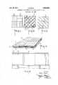
- FIG. 1 is a plan view of the covering layer
- FIG. 2 is a plan view of the middle layer
- FIG. 3 is a plan view of the underlayer
- FIG. 4 is a perspective view of the finished sheet or plate in perspective.
- FIG. 5 is a plan view of the floor covering according to the invention.
- the covering layer 1 can, as already explained, be made of cut, pared or sawn veneers.
- the layers 2 and 3 can be made out of wood chips or fibre plates; but they can also be of plastic or inorganic materials such as asbestos cement.
- the middle layer illustrated in FIG. 2 consists of continuous strips 7, between which the rabbets 6, two to three times the thickness of a layer, are left free.
- FIG. 3 shows the lowest layer with similar strips 7 and rabbets 6, which likewise run diagonally to the edges of the covering layer 1, but intersect at right angles, according to the invention, the rabbets of the middle layer.
- the lowest layer 3 already mentioned is in manner known per se offset in relation to the two upper layers 1 and 2 which coincide with one another, so that projecting parts '8 and 9 result which serve for the sticking together of the individual plates.
- the projecting edges or parts 9 mentioned can be seen particularly clearly, as the dotted lines illustrate the edges of the lowest layer 3 lying beneath them.
- a fairly large number of these separate prefabricated plates or sheets 4 are stuck together to form a floor covermg.
- an adhesive is used which is applied at the factory over the whole surface of the plate and then dried, and which after storage, for a fairly long time, is still capable of sticking if both parts to be fastened to one another are covered with the alreadydried adhesive.
- the projecting parts 8 and 9 already mentioned are also coated with the permanently adhesive glue, and a firm and immediately-effective connection of the separate plates '4 can very easily be achieved when the plates, having been put together in the manner shown in FIG. 5, are placed under pressure against one another by means of the projecting parts 8 and 9.
- tapping with a suitable hammer is suflicient.
- the floor covering according to the invention is not connected to the underfloor, this being an example of the so-called floating application.
- the result is that it is easy to lay the floor covering according to the invention on to insulating sheeting or the like, in which case minor unevennesses in the under-floor are hardly to be taken into account. No particular demands by way of firmness are made of the underfloor as is the case, for example, with known glued mosaic-parquet plates.
- Manufacture of the floor covering according to the invention is effected in the following manner. First of all, the two layers 1 and 2 are glued together. This intermediate product is then processed and sanded down to exact thickness. Thereupon the edges of the plate thus formed are trimmed and the surface is sealed. The underside of the plate so formed is then, together with the strips 7 of the underlayer 3 to be formed, coated with the glue, and the two are glued together in the offset manner illustrated in FIGS. 4 and 5. The degree of offset of the projecting parts 8 and 9 amounts to about five and eight times the total layer thickness, so that a fastening resistant to bending results.
- the frontal edges of the individual strips of the underlayer 3 are not coated with glue in advance, which results in a considerable simplification of the operation.
- the middle layer 2 and the lower layer 3 are preferably made the same thickness as the covering layer 1, and preferably relatively thin at that, about 2 to 3 mm, in order that a floor covering flexible in general effect may be obtained.
- the plates 4 themselves can have a rectangular contour as illustrated, but any other desired contour is feasible. In particular, it is possible to saw the plates up as desired for the purpose of fitting them against the walls of a room.
- the edges of the plates are preferably straight, but they can be serrated, for example if it is desired to produce a so-called herring-bone pattern.
- a laminated floor covering including at least three layers, each of said layers being composed of thin fiat strips, the strips of the topmost layer of said floor covering abutting each other to provide a substantially solid layer, the strips of the bottom and middle layers of said floor covering being composed of spaced, generally parallel strips separated by rabbets, with the strips of said bottom layer beingat an angle of about 90 to the strips of said middle layer, said upper and middle layers having the same lateral dimensions and being superimposed, and said lower layer having the same lateral dimensions as the upper and middle layers, but being olfset in relation theretO.
- a floor covering according to claim 1 wherein the strips forming at least one of the lower and middle layers are made of wood-chip board, fiber board or asbestos cement board.
- a method for producing a floor covering comprising the steps of forming a first layer of laterally abutting thin flat stri-ps, adhesively bonding to one surface of said first layer thin flat strips to form a second layer of spaced, generally parallel strips separated by rabbets adhesively bonded to said first layer, said first and second'layers having the same lateral dimensions and being superimposed and forming a plate, and thereafter adhesively bonding to the exposed surface of said second layer thin fiat strips to form a third layer of spaced, generally parallel strips separated by rabbets at an angle of about 90 to the strips of said second layer, said third layer having the same lateral dimensions as said first and second layers but being offset in relation thereto.
Landscapes
- Engineering & Computer Science (AREA)
- Architecture (AREA)
- Life Sciences & Earth Sciences (AREA)
- Wood Science & Technology (AREA)
- Civil Engineering (AREA)
- Structural Engineering (AREA)
- Floor Finish (AREA)
Abstract
A FLOORING ELEMENT IS DISCLOSED WHICH COMPRISES AT LEAST THREE LAYERS; AN UPPER LAYER WHICH FORMS THE FLOOR SURFACE, A LOWER LAYER WHICH CONTACTS THE UNDER FLOOR AND A MIDDLE LAYER; ALL LAYERS BEING BONDED BY ADHESIVES. EACH OF THE LOWER AND MIDDLE LAYERS IS COMPOSED OF CONTINUOUS STRIPS WHICH ARE PARALLEL AND SPACED APART, PREFERABLY BY A DISTANCE OF TWO TO THREE TIMES THE THICKNESS OF THE ELEMENT. THE STRIPS OF THE LOWEST AND MIDDLE LAYERS INTERSECT AT AN ANGLE OF 90*. THE VARIOUS LAYERS ARE GENERALLY SIMILAR IN HORIZONAL DIMENSIONS, AND ALL LAYERS BUT THE LOWEST ARE SUPERIMPOSED. THE LOWEST LAYER IS DIAGONALLY OFFSET TO PROVIDE A PROJECTION ON TWO SIDES WHICH PREFERABLY HAS A WIDTH WHICH IS AT LEAST 5 TO 8 TIMES THE ELEMENT THICKNESS. THESE ELEMENTS MAY BE ASSEMBLED INTO A FLOOR WITHOUT THE NECESSITY OF BONDING TO THE FLOOR BY APPLYING ADHESIVE TO THE PROJECTIONS FORMED BY THE OFFSET LOWER LAYER, LAYING A SECOND ELEMENT ADJACENT THE FIRST TO COVER THE EXTENSION OF THE FIRST AND APPLYING PRESSURE TO THE SUPERIMPOSED PORTIONS, AS BY TAPPING WITH A HAMMER.
Description
E. KUHLE Janyiz, 1911 LAMiNATED FLOOR COVERING AND METHOD OF MAKING SAME med Oct. 19. 1967 INVENTOR. 59/07 Kama BY I N XS
United States Patent O Int. 01. B521) 3/14 US. Cl. 161-38 6 Claims ABSTRACT OF THE DISCLOSURE A flooring element is disclosed which comprises at least three layers; an upper layer which forms the floor surface, a lower layer which contacts the under floor and a middle layer; all layers being bonded by adhesives. Each of the lower and middle layers is composed of continuous strips which are parallel and spaced apart, preferably by a distance of two to three times the thickness of the element. The strips of the lowest and middle layers intersect at an angle of 90. The various layers are generally similar in horizontal dimensions, and all layers but the lowest are superimposed. The lowest layer is diagonally offset to provide a projection on two sides which preferably has a width which is at least to 8 times the element thickness. These elements may be assembled into a floor without the necessity of bonding to the floor by applying adhesive to the projections formed by the oifset lower layer, laying a second element adjacent the first to cover the extension of the first and applying pressure to the superimposed portions, as by tapping with a hammer.
DISCLOSURE The invention concerns a floor covering consisting of at least three layers of thin and flexible frieze one above the other and fastened together by adhesives, the lowest being olfset in relation to the other two which coincide, and rabbets being left free between the separate elements of the middle and lowest layers.
A floor covering of that kind is already known, which has, however, the disadvantage that the rabbets in the lowest layer run at right angles to the edge of the upper layers, with the result that no adequate coinciding with or covering of the rabbets of the middle layer is ensured when the sheets are placed together in the laying of the floor covering in the building. A further disadvantage of the known floor covering resides in the fact that the in dividual elements of the middle and the lowest layers are formed only partially as short strips which do not extend the full width, whereas other strips exhibit a square or rectangular shape, as a result of which no adequate lock effect is achieved, and also no adequate dimensional stability in a changeable climate or under damp conditions inside the building.
There is known, furthermore, a flooring element for parquet-type floors consisting of two layers of soft wood glued and locked together on to which is glued a hardwood walking surface, all the layers being locked in relation to one another by means of the boards of the middle layer which are displaced by something under 45 in relation to the grain of the walking surface and the supporting layer. Each board of that middle layer has, along each longer frontal side, a fixed spring protruding in relation to the walking layer and the supporting layer and along each of the other frontal sides a groove. In addition, edge straps are provided for the improvement of the locking effect. In this case the disadvantage already mentioned of low dimensional stability occurs to a still greater extent because no rabbets of a larger kind at all are provided between the separate elements of the under-layers,
3,554,850 Patented Jan. 12, 1971 the result of that being that it is impossible to achieve any flexible property in the individual plates or sheets. In addition, the manufacture of the springs above mentioned, and also the separate finishing of the edge straps, is very expensive. Also, laying of the known floor elements without an overlapping toothed effect is not possible, which in turn excludes the possibility of factory sealing.
For the laying of the parquet plates or sheets known today, an adhesive is used which is painted on to the underfloor and into which the plates or sheets are laid. Thereupon a fairly long drying and setting period is necessary before the floor can be polished and sealed. For that reason it has hitherto been necessary to handle an adhesive on site and in addition to use further appliances such as sanding and sealing machines, all of which involves fairly heavy costs in the manual laying of the floor, as well as, always, the repeated observance of very troublesome drying periods.
The object of the present invention is to eliminate these disadvantages and in particular to create a floor of the kind mentioned above which makes possible, among other things, very rapid laying without drying periods.
For the attainment of that objective, according to the invention, the rabbets of the middle and the lowest layer intersect one another at an angle of the elements are, in a manner known per se, formed as strips; and those strips extend right through. By that means not only is the fully-operative sealing effect already mentioned achieved, which means also the maximum possible dimensional stability, but also at the same time simplicity of manufacture and laying is attained.
Wood, as is known, is liable to swell, and it alters its dimensions when dampness operates on it, and particularly when the floor is laid in new buildings which are still damp. Swelling and shrinkage are, however, avoided by locking.
A further development of the invention envisages that the width of the rabbets is two to three times as great as the thickness of the floor elements.
According to a further advantageous characteristic of the invention, the projecting parts of the layers are provided with an adhesive which is permanently adhesive. This, according to the invention, does not take place on site inside the building, but in the factory where the floor covering is made, so that the manipulation of adhesive in the building is entirely done away with.
By way of a further development of this concept, there is also provided, according to the invention, a process for the laying of the flooring of the invention in which the individual prefabricated plates or sheets are fastened to one another merely by pressure on the projecting parts already mentioned. At the same time, according to a further advantageous characteristic of the invention, the pressure in question can be applied by knocking with a hammer. Thus for the laying of the flooring according to the invention all that is necessary is a hammer and a saw for adapting the flooring to the size of the room, there being no need for any special measures for attachment to the under-floor. Further appliances such as a sanding machine, sealing agents and the like are no longer necessary in the building. When the floor layer has finished his work the room can be occupied immediately, since the most extensive dimensional stability and flexibility are olfered.
According to the invention, connection to the underfloor is avoided, an effect which is called floating floorlaying. This makes an underlay of sound-, heator moistore-insulation possible. Furthermore, laying of the floor on under-floors which are not fully dried out is possible, which was out of the question previously. It is no longer necessary to observe any drying periods after the laying and the sealing.
The connection of the floor elements to one another over an extensive surface achieved by means of the pressing according to the invention gives an exactly-defined level for the upper edge of any given plate or sheet in relation to the upper edge of the neighbouring plate or sheet, and accordingly offers a ridge-free and rabbct-free connection which is independent of unevennesses in the under-floor.
The invention also envisages a process for the manufacture of the floor covering according to the invention. According to that process, after the two upper layers have been stuck together, the plate so formed is processed and sanded to the exact thickness required, after which the edges are dressed and the surface is sealed. The intermediate product thus obtained is stuck on to the underlayer, the projecting parts already mentioned forming a projection of thickness at least five to eight times the total thickness of the plates. The adhesive already mentioned is applied over the whole surface of every plate so that an additional application of adhesive to the projecting parts in a separate operation is not necessary. This adhesive is very long-lasting and can be used even after being kept for a long time at the building site, the pressure, as already mentioned, being simply applied from above. By this method according to the invention, the plate is pre-finished in such a way that the extremely simple laying of the floor on site as already mentioned can be carried out without anyone having to put up with any disadvantages.
According to a further advantageous characteristic of the invention, when the adhesive is applied as described, the frontal edges of the individual elements are not coated with adhesive. According to the invention it is not at all necessary that any binding force should be applied transversely to the plane of the plate within a layer, because, as a result of the arrangement, according to the invention, whereby the rabbets intersect one another at right angles, the stability of the sheets or plates is fully adequate.
The covering layer of the flooring according to the invention can consist of cut, pared or sawn veneers known per se, while one or more of the lower layers can be made from veneers or of plates made of wood chips or fibre, of plastic or of inorganic materials. For example, it is advantageous to make the middle and the bottom layers of asbestos cement. These materials are particularly economical and damp-resistant, and the invention makes possible a combination with the covering layer mentioned out of wood.
Other advantages and details of the invention emerge from the following description, with reference to the drawings, of an example of embodiment of the invention.
FIG. 1 is a plan view of the covering layer;
FIG. 2 is a plan view of the middle layer;
FIG. 3 is a plan view of the underlayer;
FIG. 4 is a perspective view of the finished sheet or plate in perspective; and
FIG. 5 is a plan view of the floor covering according to the invention.
In the covering layer shown in FIG. 1 all the edges of the parts ranged hard up against one another are orientated parallel to the rims of the plate or sheet. By that means is obtained the external appearance of a sheet of parquet. In fact the floor according to the invention is not distinguishable in its aesthetic effect from a conventional parquet floor.
The covering layer 1 can, as already explained, be made of cut, pared or sawn veneers. On the other hand, the layers 2 and 3 can be made out of wood chips or fibre plates; but they can also be of plastic or inorganic materials such as asbestos cement.
The middle layer illustrated in FIG. 2 consists of continuous strips 7, between which the rabbets 6, two to three times the thickness of a layer, are left free. The edges of these strips 7, which according to the invention are continuous, run diagonally to the rims of the covering layer.
4 FIG. 3 shows the lowest layer with similar strips 7 and rabbets 6, which likewise run diagonally to the edges of the covering layer 1, but intersect at right angles, according to the invention, the rabbets of the middle layer.
As FIG. 4 shows, the lowest layer 3 already mentioned is in manner known per se offset in relation to the two upper layers 1 and 2 which coincide with one another, so that projecting parts '8 and 9 result which serve for the sticking together of the individual plates. In FIG. 5 the projecting edges or parts 9 mentioned can be seen particularly clearly, as the dotted lines illustrate the edges of the lowest layer 3 lying beneath them. As can there be seen, a fairly large number of these separate prefabricated plates or sheets 4 are stuck together to form a floor covermg.
For sticking the plates together an adhesive is used which is applied at the factory over the whole surface of the plate and then dried, and which after storage, for a fairly long time, is still capable of sticking if both parts to be fastened to one another are covered with the alreadydried adhesive.
Thereafter the projecting parts 8 and 9 already mentioned are also coated with the permanently adhesive glue, and a firm and immediately-effective connection of the separate plates '4 can very easily be achieved when the plates, having been put together in the manner shown in FIG. 5, are placed under pressure against one another by means of the projecting parts 8 and 9. For this purpose tapping with a suitable hammer is suflicient. Thus the floor covering according to the invention is not connected to the underfloor, this being an example of the so-called floating application. The result is that it is easy to lay the floor covering according to the invention on to insulating sheeting or the like, in which case minor unevennesses in the under-floor are hardly to be taken into account. No particular demands by way of firmness are made of the underfloor as is the case, for example, with known glued mosaic-parquet plates.
Manufacture of the floor covering according to the invention is effected in the following manner. First of all, the two layers 1 and 2 are glued together. This intermediate product is then processed and sanded down to exact thickness. Thereupon the edges of the plate thus formed are trimmed and the surface is sealed. The underside of the plate so formed is then, together with the strips 7 of the underlayer 3 to be formed, coated with the glue, and the two are glued together in the offset manner illustrated in FIGS. 4 and 5. The degree of offset of the projecting parts 8 and 9 amounts to about five and eight times the total layer thickness, so that a fastening resistant to bending results.
The frontal edges of the individual strips of the underlayer 3 are not coated with glue in advance, which results in a considerable simplification of the operation. The middle layer 2 and the lower layer 3 are preferably made the same thickness as the covering layer 1, and preferably relatively thin at that, about 2 to 3 mm, in order that a floor covering flexible in general effect may be obtained.
The plates 4 themselves can have a rectangular contour as illustrated, but any other desired contour is feasible. In particular, it is possible to saw the plates up as desired for the purpose of fitting them against the walls of a room. The edges of the plates are preferably straight, but they can be serrated, for example if it is desired to produce a so-called herring-bone pattern.
All the details described and illustrated are of significance for this invention.
Having now in detail described and ascertained my said invention and the manner in which the same is to be performed, I declare that what I claim is:
1. A laminated floor covering including at least three layers, each of said layers being composed of thin fiat strips, the strips of the topmost layer of said floor covering abutting each other to provide a substantially solid layer, the strips of the bottom and middle layers of said floor covering being composed of spaced, generally parallel strips separated by rabbets, with the strips of said bottom layer beingat an angle of about 90 to the strips of said middle layer, said upper and middle layers having the same lateral dimensions and being superimposed, and said lower layer having the same lateral dimensions as the upper and middle layers, but being olfset in relation theretO.
2. A floor covering according to claim 1 wherein the strips forming at least one of the lower and middle layers are made of wood-chip board, fiber board or asbestos cement board.
3. A floor covering according to claim 1 wherein the width of the space between the strips forming the middle and bottom layers is 2 to 3 times the thickness of said layers.
4. A method for producing a floor covering comprising the steps of forming a first layer of laterally abutting thin flat stri-ps, adhesively bonding to one surface of said first layer thin flat strips to form a second layer of spaced, generally parallel strips separated by rabbets adhesively bonded to said first layer, said first and second'layers having the same lateral dimensions and being superimposed and forming a plate, and thereafter adhesively bonding to the exposed surface of said second layer thin fiat strips to form a third layer of spaced, generally parallel strips separated by rabbets at an angle of about 90 to the strips of said second layer, said third layer having the same lateral dimensions as said first and second layers but being offset in relation thereto.
5. A method according to claim 4 wherein said plate is p1 ocessed and sanded to the thickness required, the edges thereof are dressed, and the surface thereof is sealed before being adhesively bonded to said third layer.
6. A method according to claim 4 wherein the strips from the first layer'are made of wood veneer, and at least one of the other layers is veneer, wood-chip board, fiber board or asbestos board.
References Cited UNITED STATES PATENTS 2,590,032 3/1952 Petry 161-38X 3,279,138 10/1966 Dittmar 161-56X 2, 35,936 5/1958 Elmendorf 161-56X I FOREIGN PATENTS 258,794 5/1949 Switzerland 52-490 PHILIP DIER, Primary Examiner US. Cl. X.R.
Applications Claiming Priority (1)
| Application Number | Priority Date | Filing Date | Title |
|---|---|---|---|
| DEK0060502 | 1966-10-20 |
Publications (1)
| Publication Number | Publication Date |
|---|---|
| US3554850A true US3554850A (en) | 1971-01-12 |
Family
ID=7229634
Family Applications (1)
| Application Number | Title | Priority Date | Filing Date |
|---|---|---|---|
| US676548A Expired - Lifetime US3554850A (en) | 1966-10-20 | 1967-10-19 | Laminated floor covering and method of making same |
Country Status (3)
| Country | Link |
|---|---|
| US (1) | US3554850A (en) |
| AT (1) | AT288000B (en) |
| CH (1) | CH469160A (en) |
Cited By (48)
| Publication number | Priority date | Publication date | Assignee | Title |
|---|---|---|---|---|
| US3789557A (en) * | 1970-06-08 | 1974-02-05 | R Harvey | Raised flooring |
| US3902293A (en) * | 1973-02-06 | 1975-09-02 | Atlantic Richfield Co | Dimensionally-stable, resilient floor tile |
| US4090338A (en) * | 1976-12-13 | 1978-05-23 | B 3 L | Parquet floor elements and parquet floor composed of such elements |
| US4388788A (en) * | 1980-07-31 | 1983-06-21 | Penn Wood Products Co. | Wood floor panel |
| US4390580A (en) * | 1981-08-26 | 1983-06-28 | Donovan William J | High pressure laminate for access floor panels |
| WO1984000785A1 (en) * | 1982-08-20 | 1984-03-01 | Jacob Abrahams | Factory-finished plywood floor covering |
| US5042214A (en) * | 1990-06-20 | 1991-08-27 | Howard Manufacturing Company | Self-locking ceiling panels |
| US5906082A (en) * | 1997-09-04 | 1999-05-25 | Counihan; James | Resilient flooring system |
| US6367217B1 (en) | 1999-11-04 | 2002-04-09 | Robbins, Inc. | Sleeper assembly for resilient hardwood floor system |
| US20030182880A1 (en) * | 1994-12-27 | 2003-10-02 | Weaber Matthew G. | Reinforced stair tread and methods for making same |
| US20040177584A1 (en) * | 2003-03-06 | 2004-09-16 | Valinge Aluminium Ab | Flooring and method for installation and manufacturing thereof |
| US20040213946A1 (en) * | 2003-04-28 | 2004-10-28 | Tef, Inc. | Hard surface-veneer engineered surfacing tiles and methods |
| US20050210810A1 (en) * | 2003-12-02 | 2005-09-29 | Valinge Aluminium Ab | Floorboard, system and method for forming a flooring, and a flooring formed thereof |
| US20060032168A1 (en) * | 2003-01-08 | 2006-02-16 | Thiers Bernard P J | Floor panel, its laying and manufacturing methods |
| US20060070333A1 (en) * | 2002-04-03 | 2006-04-06 | Darko Pervan | Mechanical locking system for floorboards |
| US20060154113A1 (en) * | 2004-12-09 | 2006-07-13 | Fuji Electric Device Technology Co., Ltd. | Perpendicular magnetic recording medium and magnetic recording device |
| US20060196139A1 (en) * | 2001-09-20 | 2006-09-07 | Valinge Innovation Ab, Apelvagen 2 | Flooring And Method For Laying And Manufacturing The Same |
| US20060236642A1 (en) * | 2005-03-30 | 2006-10-26 | Valinge Aluminium Ab | Mechanical locking system for panels and method of installing same |
| US20060260254A1 (en) * | 2005-05-20 | 2006-11-23 | Valinge Aluminium Ab | Mechanical Locking System For Floor Panels |
| US7155871B1 (en) | 2005-12-29 | 2007-01-02 | Tru Woods Limited | Floor plank |
| US20070044403A1 (en) * | 2005-08-30 | 2007-03-01 | Svein Julton | Floor coverings with wooden floors on a substrate, method for the covering of a substrate and use of studded plates |
| US20070163194A1 (en) * | 2005-12-29 | 2007-07-19 | Tru Woods Limited | Floor tile |
| US20070175148A1 (en) * | 2006-01-12 | 2007-08-02 | Valinge Innovation Ab | Resilient groove |
| US20080005997A1 (en) * | 2002-04-22 | 2008-01-10 | Valinge Innovation Ab | Floorboards, flooring systems and method for manufacturing and installation thereof |
| US20080110125A1 (en) * | 2006-11-15 | 2008-05-15 | Valinge Innovation Ab | Mechanical Locking Of Floor Panels With Vertical Folding |
| US20080134614A1 (en) * | 2004-10-22 | 2008-06-12 | Valinge Innovation Ab | Mechanical locking system for panels and method of installing same |
| US20080134613A1 (en) * | 2006-12-08 | 2008-06-12 | Valinge Innovation Ab | Mechanical Locking of Floor Panels |
| US7441384B2 (en) | 2002-08-14 | 2008-10-28 | Columbia Insurance Company | Pre-glued tongue and groove flooring |
| EP2150401A1 (en) * | 2007-05-25 | 2010-02-10 | Tru Woods Limited | Floor member |
| ES2334001A1 (en) * | 2007-11-22 | 2010-03-03 | Jesus Maria Martin Camara | Set of pavement of tarima, to mount on rastrels or floating, and special cover for heated or refrigerated soleras. (Machine-translation by Google Translate, not legally binding) |
| US7721503B2 (en) | 2006-07-14 | 2010-05-25 | Valinge Innovation Ab | Locking system comprising a combination lock for panels |
| US7779601B2 (en) | 2001-09-20 | 2010-08-24 | Valinge Innovation Ab | Flooring and method for laying and manufacturing the same |
| US20100300031A1 (en) * | 2006-07-11 | 2010-12-02 | Valinge Innovation Ab | Mechanical locking of floor panels with a flexible bristle tongue |
| EP2484845A2 (en) | 2011-02-08 | 2012-08-08 | Sunstate Import/Export, Inc. | Self locking flooring panels |
| US20130104484A1 (en) * | 2010-05-17 | 2013-05-02 | William Thornton | Substructure for Supporting a Wood Flooring and Flooring System Comprising the Same |
| US8584423B2 (en) | 2001-07-27 | 2013-11-19 | Valinge Innovation Ab | Floor panel with sealing means |
| US8756899B2 (en) | 2009-09-04 | 2014-06-24 | Valinge Innovation Ab | Resilient floor |
| US8800150B2 (en) | 2003-02-24 | 2014-08-12 | Valinge Innovation Ab | Floorboard and method for manufacturing thereof |
| US9314936B2 (en) | 2011-08-29 | 2016-04-19 | Valinge Flooring Technology Ab | Mechanical locking system for floor panels |
| US9322183B2 (en) | 2004-01-13 | 2016-04-26 | Valinge Innovation Ab | Floor covering and locking systems |
| US9528276B2 (en) | 1998-06-03 | 2016-12-27 | Valinge Innovation Ab | Locking system and flooring board |
| US9567753B2 (en) | 1999-04-30 | 2017-02-14 | Valinge Innovation Ab | Locking system, floorboard comprising such a locking system, as well as method for making floorboards |
| US10059084B2 (en) | 2014-07-16 | 2018-08-28 | Valinge Innovation Ab | Method to produce a thermoplastic wear resistant foil |
| US10301830B2 (en) | 2013-03-25 | 2019-05-28 | Valinge Innovation Ab | Floorboards provided with a mechanical locking system |
| US10486399B2 (en) | 1999-12-14 | 2019-11-26 | Valinge Innovation Ab | Thermoplastic planks and methods for making the same |
| US10801213B2 (en) | 2018-01-10 | 2020-10-13 | Valinge Innovation Ab | Subfloor joint |
| US11578495B2 (en) | 2018-12-05 | 2023-02-14 | Valinge Innovation Ab | Subfloor joint |
| US11725395B2 (en) | 2009-09-04 | 2023-08-15 | Välinge Innovation AB | Resilient floor |
Families Citing this family (2)
| Publication number | Priority date | Publication date | Assignee | Title |
|---|---|---|---|---|
| DE9420216U1 (en) * | 1994-12-19 | 1995-02-09 | Kroenig Hans | Solid wood element |
| FR2729986A1 (en) * | 1995-01-27 | 1996-08-02 | France Bois Impregnes Sa | Duckboard for constructing temporary wood platforms |
-
1967
- 1967-08-10 CH CH1137567A patent/CH469160A/en unknown
- 1967-09-13 AT AT836567A patent/AT288000B/en not_active IP Right Cessation
- 1967-10-19 US US676548A patent/US3554850A/en not_active Expired - Lifetime
Cited By (131)
| Publication number | Priority date | Publication date | Assignee | Title |
|---|---|---|---|---|
| US3789557A (en) * | 1970-06-08 | 1974-02-05 | R Harvey | Raised flooring |
| US3902293A (en) * | 1973-02-06 | 1975-09-02 | Atlantic Richfield Co | Dimensionally-stable, resilient floor tile |
| US4090338A (en) * | 1976-12-13 | 1978-05-23 | B 3 L | Parquet floor elements and parquet floor composed of such elements |
| US4388788A (en) * | 1980-07-31 | 1983-06-21 | Penn Wood Products Co. | Wood floor panel |
| US4390580A (en) * | 1981-08-26 | 1983-06-28 | Donovan William J | High pressure laminate for access floor panels |
| WO1984000785A1 (en) * | 1982-08-20 | 1984-03-01 | Jacob Abrahams | Factory-finished plywood floor covering |
| US5042214A (en) * | 1990-06-20 | 1991-08-27 | Howard Manufacturing Company | Self-locking ceiling panels |
| US6860071B2 (en) * | 1994-12-27 | 2005-03-01 | Weaber, Inc. | Reinforced stair tread and methods for making same |
| US20030182880A1 (en) * | 1994-12-27 | 2003-10-02 | Weaber Matthew G. | Reinforced stair tread and methods for making same |
| US5906082A (en) * | 1997-09-04 | 1999-05-25 | Counihan; James | Resilient flooring system |
| US9528276B2 (en) | 1998-06-03 | 2016-12-27 | Valinge Innovation Ab | Locking system and flooring board |
| US9567753B2 (en) | 1999-04-30 | 2017-02-14 | Valinge Innovation Ab | Locking system, floorboard comprising such a locking system, as well as method for making floorboards |
| US6367217B1 (en) | 1999-11-04 | 2002-04-09 | Robbins, Inc. | Sleeper assembly for resilient hardwood floor system |
| US6637169B2 (en) | 1999-11-04 | 2003-10-28 | Robbins, Inc. | Sleeper assembly for resilient hardwood floor system |
| US10486399B2 (en) | 1999-12-14 | 2019-11-26 | Valinge Innovation Ab | Thermoplastic planks and methods for making the same |
| US10975580B2 (en) | 2001-07-27 | 2021-04-13 | Valinge Innovation Ab | Floor panel with sealing means |
| US8584423B2 (en) | 2001-07-27 | 2013-11-19 | Valinge Innovation Ab | Floor panel with sealing means |
| US7788871B2 (en) | 2001-09-20 | 2010-09-07 | Valinge Innovation Ab | Flooring and method for laying and manufacturing the same |
| US20060196139A1 (en) * | 2001-09-20 | 2006-09-07 | Valinge Innovation Ab, Apelvagen 2 | Flooring And Method For Laying And Manufacturing The Same |
| US8250825B2 (en) | 2001-09-20 | 2012-08-28 | Välinge Innovation AB | Flooring and method for laying and manufacturing the same |
| US20080028713A1 (en) * | 2001-09-20 | 2008-02-07 | Valinge Innovation Ab | Flooring and method for laying and manufacturing the same |
| US8069631B2 (en) | 2001-09-20 | 2011-12-06 | Valinge Innovation Ab | Flooring and method for laying and manufacturing the same |
| US7779601B2 (en) | 2001-09-20 | 2010-08-24 | Valinge Innovation Ab | Flooring and method for laying and manufacturing the same |
| US7637068B2 (en) | 2002-04-03 | 2009-12-29 | Valinge Innovation Ab | Mechanical locking system for floorboards |
| US7841150B2 (en) | 2002-04-03 | 2010-11-30 | Valinge Innovation Ab | Mechanical locking system for floorboards |
| US20060070333A1 (en) * | 2002-04-03 | 2006-04-06 | Darko Pervan | Mechanical locking system for floorboards |
| US7757452B2 (en) | 2002-04-03 | 2010-07-20 | Valinge Innovation Ab | Mechanical locking system for floorboards |
| US8104244B2 (en) | 2002-04-22 | 2012-01-31 | Valinge Innovation Ab | Floorboards, flooring systems and method for manufacturing and installation thereof |
| US20080168736A1 (en) * | 2002-04-22 | 2008-07-17 | Valinge Innovation Ab | Floorboards, flooring systems and method for manufacturing and installation thereof |
| US8359806B2 (en) | 2002-04-22 | 2013-01-29 | Valinge Innovation Ab | Floorboards, flooring systems and methods for manufacturing and installation thereof |
| US20080005997A1 (en) * | 2002-04-22 | 2008-01-10 | Valinge Innovation Ab | Floorboards, flooring systems and method for manufacturing and installation thereof |
| US7716896B2 (en) | 2002-04-22 | 2010-05-18 | Valinge Innovation Ab | Floorboards, flooring systems and method for manufacturing and installation thereof |
| US7895805B2 (en) | 2002-04-22 | 2011-03-01 | Valinge Innovation Ab | Floorboards, flooring systems and method for manufacturing and installation thereof |
| US20080209837A1 (en) * | 2002-04-22 | 2008-09-04 | Valinge Innovation Ab | Floorboards, flooring systems and methods for manufacturing and installation thereof |
| US20080209838A1 (en) * | 2002-04-22 | 2008-09-04 | Valinge Innovation Ab | Floorboards, flooring systems and method for manufacturing and installation thereof |
| US7441384B2 (en) | 2002-08-14 | 2008-10-28 | Columbia Insurance Company | Pre-glued tongue and groove flooring |
| US20060032168A1 (en) * | 2003-01-08 | 2006-02-16 | Thiers Bernard P J | Floor panel, its laying and manufacturing methods |
| US9410328B2 (en) | 2003-02-24 | 2016-08-09 | Valinge Innovation Ab | Floorboard and method for manufacturing thereof |
| US8800150B2 (en) | 2003-02-24 | 2014-08-12 | Valinge Innovation Ab | Floorboard and method for manufacturing thereof |
| US10137659B2 (en) | 2003-02-24 | 2018-11-27 | Valinge Innovation Ab | Floorboard and method for manufacturing thereof |
| US20040177584A1 (en) * | 2003-03-06 | 2004-09-16 | Valinge Aluminium Ab | Flooring and method for installation and manufacturing thereof |
| US7845140B2 (en) | 2003-03-06 | 2010-12-07 | Valinge Innovation Ab | Flooring and method for installation and manufacturing thereof |
| US7993731B2 (en) | 2003-04-28 | 2011-08-09 | Shaw Industries Group, Inc. | Hard surface-veneer engineered surfacing tiles |
| US20040213946A1 (en) * | 2003-04-28 | 2004-10-28 | Tef, Inc. | Hard surface-veneer engineered surfacing tiles and methods |
| US7442423B2 (en) | 2003-04-28 | 2008-10-28 | Shaw Industries Group | Hard surface-veneer engineered surfacing tiles |
| US20060154015A1 (en) * | 2003-04-28 | 2006-07-13 | Miller Robert J | Hard surface-veneer engineered surfacing tiles and methods |
| US9970199B2 (en) | 2003-12-02 | 2018-05-15 | Valinge Innovation Ab | Floorboard, system and method for forming a flooring, and a flooring formed thereof |
| US7886497B2 (en) * | 2003-12-02 | 2011-02-15 | Valinge Innovation Ab | Floorboard, system and method for forming a flooring, and a flooring formed thereof |
| US20080172971A1 (en) * | 2003-12-02 | 2008-07-24 | Valinge Innovation Ab | Floor covering and laying methods |
| US8613826B2 (en) | 2003-12-02 | 2013-12-24 | Valinge Innovation Ab | Floorboard, system and method for forming a flooring, and a flooring formed thereof |
| US8293058B2 (en) | 2003-12-02 | 2012-10-23 | Valinge Innovation Ab | Floorboard, system and method for forming a flooring, and a flooring formed thereof |
| US9605436B2 (en) | 2003-12-02 | 2017-03-28 | Valinge Innovation Ab | Floorboard, system and method for forming a flooring, and a flooring formed thereof |
| US7568322B2 (en) * | 2003-12-02 | 2009-08-04 | Valinge Aluminium Ab | Floor covering and laying methods |
| US20050210810A1 (en) * | 2003-12-02 | 2005-09-29 | Valinge Aluminium Ab | Floorboard, system and method for forming a flooring, and a flooring formed thereof |
| US10138637B2 (en) | 2004-01-13 | 2018-11-27 | Valinge Innovation Ab | Floor covering and locking systems |
| US9322183B2 (en) | 2004-01-13 | 2016-04-26 | Valinge Innovation Ab | Floor covering and locking systems |
| US7841145B2 (en) | 2004-10-22 | 2010-11-30 | Valinge Innovation Ab | Mechanical locking system for panels and method of installing same |
| US20080066415A1 (en) * | 2004-10-22 | 2008-03-20 | Darko Pervan | Mechanical locking system for panels and method of installing same |
| US8042311B2 (en) | 2004-10-22 | 2011-10-25 | Valinge Innovation Ab | Mechanical locking system for panels and method of installing same |
| US8707650B2 (en) | 2004-10-22 | 2014-04-29 | Valinge Innovation Ab | Mechanical locking system for panels and method of installing same |
| US8341915B2 (en) | 2004-10-22 | 2013-01-01 | Valinge Innovation Ab | Mechanical locking of floor panels with a flexible tongue |
| US20080134614A1 (en) * | 2004-10-22 | 2008-06-12 | Valinge Innovation Ab | Mechanical locking system for panels and method of installing same |
| US20060154113A1 (en) * | 2004-12-09 | 2006-07-13 | Fuji Electric Device Technology Co., Ltd. | Perpendicular magnetic recording medium and magnetic recording device |
| US20080034708A1 (en) * | 2005-03-30 | 2008-02-14 | Valinge Innovation Ab | Mechanical locking system for panels and method of installing same |
| US8387327B2 (en) | 2005-03-30 | 2013-03-05 | Valinge Innovation Ab | Mechanical locking system for floor panels |
| US20060236642A1 (en) * | 2005-03-30 | 2006-10-26 | Valinge Aluminium Ab | Mechanical locking system for panels and method of installing same |
| US20110088345A1 (en) * | 2005-03-30 | 2011-04-21 | Valinge Innovation Ab | Mechanical locking system for panels and method of installing same |
| US7866110B2 (en) | 2005-03-30 | 2011-01-11 | Valinge Innovation Ab | Mechanical locking system for panels and method of installing same |
| US8677714B2 (en) | 2005-03-30 | 2014-03-25 | Valinge Innovation Ab | Mechanical locking system for panels and method of installing same |
| US8079196B2 (en) | 2005-03-30 | 2011-12-20 | Valinge Innovation Ab | Mechanical locking system for panels |
| US7841144B2 (en) | 2005-03-30 | 2010-11-30 | Valinge Innovation Ab | Mechanical locking system for panels and method of installing same |
| US8061104B2 (en) | 2005-05-20 | 2011-11-22 | Valinge Innovation Ab | Mechanical locking system for floor panels |
| US20060260254A1 (en) * | 2005-05-20 | 2006-11-23 | Valinge Aluminium Ab | Mechanical Locking System For Floor Panels |
| US8171692B2 (en) | 2005-05-20 | 2012-05-08 | Valinge Innovation Ab | Mechanical locking system for floor panels |
| US20080000187A1 (en) * | 2005-05-20 | 2008-01-03 | Valinge Innovation Ab | Mechanical locking system for floor panels |
| US8733065B2 (en) | 2005-05-20 | 2014-05-27 | Valinge Innovation Ab | Mechanical locking system for floor panels |
| US20070044403A1 (en) * | 2005-08-30 | 2007-03-01 | Svein Julton | Floor coverings with wooden floors on a substrate, method for the covering of a substrate and use of studded plates |
| US8132377B2 (en) * | 2005-08-30 | 2012-03-13 | Isola As | Floor coverings with wooden floors on a substrate, method for the covering of a substrate and use of studded plates |
| US20070163194A1 (en) * | 2005-12-29 | 2007-07-19 | Tru Woods Limited | Floor tile |
| EP1811103A1 (en) | 2005-12-29 | 2007-07-25 | Tru Woods Limited | Floor tile being a laminate of two layers of flexible plastic sheet material laminated together in offset relationship |
| US20070175137A1 (en) * | 2005-12-29 | 2007-08-02 | Tru Woods Limited. | Floor plank |
| US7322159B2 (en) | 2005-12-29 | 2008-01-29 | Tru Woods Limited | Floor plank |
| US7458191B2 (en) | 2005-12-29 | 2008-12-02 | Tru Woods Limited | Floor tile |
| EP1803869A1 (en) | 2005-12-29 | 2007-07-04 | Tru Woods Limited | Floor plank being a laminate of two layers of flexible plastic sheet material laminated together in offset relationship |
| US7155871B1 (en) | 2005-12-29 | 2007-01-02 | Tru Woods Limited | Floor plank |
| US7930862B2 (en) | 2006-01-12 | 2011-04-26 | Valinge Innovation Ab | Floorboards having a resilent surface layer with a decorative groove |
| US9222267B2 (en) | 2006-01-12 | 2015-12-29 | Valinge Innovation Ab | Set of floorboards having a resilient groove |
| US8245478B2 (en) | 2006-01-12 | 2012-08-21 | Välinge Innovation AB | Set of floorboards with sealing arrangement |
| US11702847B2 (en) | 2006-01-12 | 2023-07-18 | Valinge Innovation Ab | Floorboards comprising a decorative edge part in a resilient surface layer |
| US20070175148A1 (en) * | 2006-01-12 | 2007-08-02 | Valinge Innovation Ab | Resilient groove |
| US8511031B2 (en) | 2006-01-12 | 2013-08-20 | Valinge Innovation Ab | Set F floorboards with overlapping edges |
| US11066836B2 (en) | 2006-01-12 | 2021-07-20 | Valinge Innovation Ab | Floorboards comprising a decorative edge part in a resilient surface layer |
| US9765530B2 (en) | 2006-01-12 | 2017-09-19 | Valinge Innovation Ab | Floorboards comprising a decorative edge part in a resilient surface layer |
| US10450760B2 (en) | 2006-01-12 | 2019-10-22 | Valinge Innovation Ab | Floorboards comprising a decorative edge part in a resilient surface layer |
| US20110154763A1 (en) * | 2006-01-12 | 2011-06-30 | Valinge Innovation Ab | Resilient groove |
| US20100300031A1 (en) * | 2006-07-11 | 2010-12-02 | Valinge Innovation Ab | Mechanical locking of floor panels with a flexible bristle tongue |
| US20110088344A1 (en) * | 2006-07-11 | 2011-04-21 | Valinge Innovation Ab | Mechanical locking of floor panels with a flexible bristle tongue |
| US7908815B2 (en) | 2006-07-11 | 2011-03-22 | Valinge Innovation Ab | Mechanical locking of floor panels with a flexible bristle tongue |
| US8033074B2 (en) | 2006-07-11 | 2011-10-11 | Valinge Innovation Ab | Mechanical locking of floor panels with a flexible bristle tongue |
| US8844236B2 (en) | 2006-07-11 | 2014-09-30 | Valinge Innovation Ab | Mechanical locking of floor panels with a flexible bristle tongue |
| US8359805B2 (en) | 2006-07-11 | 2013-01-29 | Valinge Innovation Ab | Mechanical locking of floor panels with a flexible bristle tongue |
| US8341914B2 (en) | 2006-07-11 | 2013-01-01 | Valinge Innovation Ab | Mechanical locking of floor panels with a flexible bristle tongue |
| US7721503B2 (en) | 2006-07-14 | 2010-05-25 | Valinge Innovation Ab | Locking system comprising a combination lock for panels |
| US7861482B2 (en) | 2006-07-14 | 2011-01-04 | Valinge Innovation Ab | Locking system comprising a combination lock for panels |
| US8689512B2 (en) | 2006-11-15 | 2014-04-08 | Valinge Innovation Ab | Mechanical locking of floor panels with vertical folding |
| US20080110125A1 (en) * | 2006-11-15 | 2008-05-15 | Valinge Innovation Ab | Mechanical Locking Of Floor Panels With Vertical Folding |
| US8869485B2 (en) | 2006-12-08 | 2014-10-28 | Valinge Innovation Ab | Mechanical locking of floor panels |
| US20080134613A1 (en) * | 2006-12-08 | 2008-06-12 | Valinge Innovation Ab | Mechanical Locking of Floor Panels |
| EP2150401A1 (en) * | 2007-05-25 | 2010-02-10 | Tru Woods Limited | Floor member |
| EP2150401A4 (en) * | 2007-05-25 | 2010-10-06 | Tru Woods Ltd | Floor member |
| US8250824B2 (en) | 2007-05-25 | 2012-08-28 | Tower IPCO Company | Floor member |
| CN101687381B (en) * | 2007-05-25 | 2013-10-23 | 特鲁木材有限公司 | Floor member |
| US20100170179A1 (en) * | 2007-05-25 | 2010-07-08 | Tru Woods Limited | Floor member |
| ES2334001A1 (en) * | 2007-11-22 | 2010-03-03 | Jesus Maria Martin Camara | Set of pavement of tarima, to mount on rastrels or floating, and special cover for heated or refrigerated soleras. (Machine-translation by Google Translate, not legally binding) |
| US9249581B2 (en) | 2009-09-04 | 2016-02-02 | Valinge Innovation Ab | Resilient floor |
| US11725395B2 (en) | 2009-09-04 | 2023-08-15 | Välinge Innovation AB | Resilient floor |
| US8756899B2 (en) | 2009-09-04 | 2014-06-24 | Valinge Innovation Ab | Resilient floor |
| US20130104484A1 (en) * | 2010-05-17 | 2013-05-02 | William Thornton | Substructure for Supporting a Wood Flooring and Flooring System Comprising the Same |
| AU2011254867B2 (en) * | 2010-05-17 | 2017-02-02 | Tarkett Gdl | Substructure for supporting a flooring and flooring system comprising the same |
| EP2572062B1 (en) * | 2010-05-17 | 2017-06-14 | Tarkett GDL | Substructure for supporting a flooring and flooring system comprising the same |
| US9359775B2 (en) * | 2010-05-17 | 2016-06-07 | Tarkett Gdl S.A. | Substructure for supporting a wood flooring and flooring system comprising the same |
| US8534023B2 (en) | 2011-02-08 | 2013-09-17 | Sunstate Import/Export, Inc. | Self locking flooring panels and related methods |
| EP2484845A2 (en) | 2011-02-08 | 2012-08-08 | Sunstate Import/Export, Inc. | Self locking flooring panels |
| US9314936B2 (en) | 2011-08-29 | 2016-04-19 | Valinge Flooring Technology Ab | Mechanical locking system for floor panels |
| US10301830B2 (en) | 2013-03-25 | 2019-05-28 | Valinge Innovation Ab | Floorboards provided with a mechanical locking system |
| US11898356B2 (en) | 2013-03-25 | 2024-02-13 | Välinge Innovation AB | Floorboards provided with a mechanical locking system |
| US10059084B2 (en) | 2014-07-16 | 2018-08-28 | Valinge Innovation Ab | Method to produce a thermoplastic wear resistant foil |
| US10493731B2 (en) | 2014-07-16 | 2019-12-03 | Valinge Innovation Ab | Method to produce a thermoplastic wear resistant foil |
| US10941578B2 (en) | 2018-01-10 | 2021-03-09 | Valinge Innovation Ab | Subfloor joint |
| US10801213B2 (en) | 2018-01-10 | 2020-10-13 | Valinge Innovation Ab | Subfloor joint |
| US11578495B2 (en) | 2018-12-05 | 2023-02-14 | Valinge Innovation Ab | Subfloor joint |
Also Published As
| Publication number | Publication date |
|---|---|
| AT288000B (en) | 1971-02-10 |
| CH469160A (en) | 1969-02-28 |
Similar Documents
| Publication | Publication Date | Title |
|---|---|---|
| US3554850A (en) | Laminated floor covering and method of making same | |
| US2894292A (en) | Combination sub-floor and top floor | |
| US5438809A (en) | Modular tile flooring system | |
| RU2307219C2 (en) | Floor boarding battens | |
| US3579941A (en) | Wood parquet block flooring unit | |
| US2337156A (en) | Wood tile flooring | |
| US6428871B1 (en) | Method of manufacturing decorative wood products from engineered wood products | |
| US3287203A (en) | Hardwood flooring | |
| US2280071A (en) | Laminated flooring | |
| NO139933B (en) | FINISHED PARQUET ELEMENT. | |
| RU2382856C2 (en) | Method for manufacturing of flat panel (versions) and panel for floorings, facing of walls and ceilings (versions) | |
| JP3433133B2 (en) | Bamboo laminated flooring manufacturing method, bamboo laminated flooring manufactured by the manufacturing method, and floor structure using the bamboo laminated flooring | |
| CN101652522A (en) | Improved hardwood flooring system | |
| US2758044A (en) | Laminated flooring | |
| JPH0953319A (en) | Woody floor member | |
| US1433077A (en) | Veneering | |
| JPH10102743A (en) | Decorative laminated sheet with groove | |
| JPH0771106A (en) | Decorated floor material | |
| JP2781027B2 (en) | Wood flooring | |
| US1626117A (en) | Flooring material | |
| US2807057A (en) | Flooring | |
| JP2516001Y2 (en) | Wood veneer | |
| JP2602096Y2 (en) | Durable floorboard | |
| JPS6141896Y2 (en) | ||
| EP0138846B1 (en) | Lining material for covering floors, walls, ceilings and columns |