US3581663A - Control apparatus - Google Patents
Control apparatus Download PDFInfo
- Publication number
- US3581663A US3581663A US768301A US3581663DA US3581663A US 3581663 A US3581663 A US 3581663A US 768301 A US768301 A US 768301A US 3581663D A US3581663D A US 3581663DA US 3581663 A US3581663 A US 3581663A
- Authority
- US
- United States
- Prior art keywords
- axis
- fluid flow
- hub
- deflector
- turbine
- Prior art date
- Legal status (The legal status is an assumption and is not a legal conclusion. Google has not performed a legal analysis and makes no representation as to the accuracy of the status listed.)
- Expired - Lifetime
Links
Images
Classifications
-
- F—MECHANICAL ENGINEERING; LIGHTING; HEATING; WEAPONS; BLASTING
- F42—AMMUNITION; BLASTING
- F42C—AMMUNITION FUZES; ARMING OR SAFETY MEANS THEREFOR
- F42C15/00—Arming-means in fuzes; Safety means for preventing premature detonation of fuzes or charges
- F42C15/28—Arming-means in fuzes; Safety means for preventing premature detonation of fuzes or charges operated by flow of fluent material, e.g. shot, fluids
- F42C15/295—Arming-means in fuzes; Safety means for preventing premature detonation of fuzes or charges operated by flow of fluent material, e.g. shot, fluids operated by a turbine or a propeller; Mounting means therefor
Definitions
- CONTROL APPARATUS l0Z/2,416/203 ABSTRACT An omnidirectional turbine providing a rota- [51] F42c 15/28 tional output of one sense in response to fluid flow ap- [50] Field 102/2-4, proaching the turbine from any direction.
- the invention is 81.2, 86; 416/203, 243; 73/189, 229; 46/53, 58 contemplated for use with air-arming munition fuzes.
- the present invention is concerned with flow sensing and, more particularly, to turbines providing a rotational output in response to fluid flow relative to the turbine.
- the invention is contemplated for use with air-arming munitions and, more particularly, with percussive fuzes in which there is a rotary vane for arming operated by relative motion of a fluid.
- the present invention concerns a turbine with a predetermined sense of rotation to extract energy from a moving fluid independent of orientation relative to the line of fluid flow.
- the turbine comprises a plurality of deflector elements mounted on an output shaft.
- the deflector elements are so oriented that fluid flow from a given direction will cause a number of them to be dominant while fluid flow from the opposite direction causes a second number of elements to be dominant.
- the orientation of the deflector elements is such that the turbineis caused to rotate in the same direction in response to forces dominant on either group.
- FIG. 1 shows a preferred embodiment of the present invention
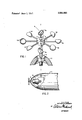
- FIG. 2 shows the preferred embodiment of FIG. 1 in combination with a fuze mounted within a bomb.
- a hub l is fixed to a shaft 2 having an axis of rotation aa and rotatably mounted in a support 3.
- Affixed to hub l are a plurality of deflector elements 4a to 4h lying in a plane substantially perpendicular to axis aa.
- Each of deflector elements 4 has an axis bb (as shown on element 4e) along which in a first direction the element offers maximum resistance to fluid flow, while it offers a relatively lesser resistance in the opposite direction as well as any other direction.
- the deflector elements are affixed to hub l by means of connecting rods such that the respective axes bb of alternate deflector elements are oriented at like angles with a plane normal to axis aa.
- the axes bb of adjacent deflector elements form equal angles with the plane perpendicular to axis aa through the point of attachment, above and below the plane, respectively.
- Arrow 5 designates the sense of rotation of the embodiment shown.
- Shaft 2 provides a support for the turbine as well as an output for coupling the rotary motion of hub l to a desired point of application.
- FIG. 2 shows the preferred embodiment of the invention coupled to a fuze 10 through shaft 2.
- Fuze 10 is mounted within a bomb ll.
- OPERATION Operation of the invention depends on the effect of fluid flow on each of the deflector elements 4.
- Each of the deflector elements 4 has an axis bb along which, in one direction, a fluid will exert maximum force on the deflector.
- a fluid flowing along the axis bb in the opposite direction will have a lesser effect on the deflector due to the rounded surface in that direction.
- fluid flow incident from any other direction will have a lesser effect than flow directly into the open cup of the deflector.
- elements 4a, 40, 4e and 4g are positioned such that fluid flow downward along the axis aa will exert a pressure in the clockwise direction on the hub, tending to rotate it in the direction indicated by arrow 5.
- the alternate elements 4b, 4d, 4f and fh are positioned such that they provide a lesser counterclockwise torque to the hub 1 in response to fluid flow downward along the axis aa.
- the elements 4b, 4d, 4f and 4! will exert a torque to the hub l in the clockwise direction while the alternate deflector elements 40, 40, 4e and 43, due to their orientation, provide a minimal torque.
- Fluid flow approaching the turbine at an angle to the axis aa will again cause rotation in the direction shown by arrow 5 independent of the orientation of the flow relative to the axis aa.
- arrow 5 independent of the orientation of the flow relative to the axis aa.
- Deflector elements 4c and 4g Due to the orientation of deflector elements 4c and 4g, there will be no torque exerted on the huh I by these elements.
- Deflector elements 4d, 4e and 4f will exert a slight torque on hub l in the counterclockwise direction.
- Deflector elements 4a, 4b and 4h are oriented to provide a substantial torque in the clockwise direction as shown by arrow 5.
- the deflector elements 4 may take many shapes, the only requirement being that they produce a torque on the hub tending to rotate it in a given direction. It will be realized that the sensitivity and speed of rotation may be adjusted by varying the size and shape of the deflector elements, the number of elements, the mounting angle, or the distance at which the deflector elements are mounted from the axis of rotation.
- An omnidirectional turbine comprising:
- hub means for rotation about an axis
- a plurality of deflector means each having a configuration offering a maximum resistance to fluid flow from one direction while offering a relatively lesser resistance from any other direction, affixed to said hub means, for providing a net torque of a first sense to said hub in response to fluid flow in any direction relative to said turbine.
- said plurality of deflector means comprises eight deflector elements positioned at equal angles around the perimeter of said hub means, said deflector means for providing said torque of a first sense about said axis in response to fluid flow perpendicular to said axis with alternate elements responsive to fluid flow along said axis in opposite directions causing a torque about said axis of said first sense.
Abstract
An omnidirectional turbine providing a rotational output of one sense in response to fluid flow approaching the turbine from any direction. The invention is contemplated for use with air-arming munition fuzes.
Description
States atent Unite a [72] Inventor Arthur M. Lohmann Hopkins, Mich.
.m M A d n a g n H m mm R mm T. mmm mm m "we UMR 6b 6 C elm .3 W eRm .mwh KB m M 99 wk flflmm 34 b 3 8 d I. we Wm. 72 a 14 mo flU 22 PA hm c .1 M 1 mwmfl wlep nhwm .E a m 6 u 7O -HM 0 de N Wm L Hg 0 P i Pnufls AFPA 1.1.1.] 253 2247 11.1.1
[54] CONTROL APPARATUS l0Z/2,416/203 ABSTRACT: An omnidirectional turbine providing a rota- [51] F42c 15/28 tional output of one sense in response to fluid flow ap- [50] Field 102/2-4, proaching the turbine from any direction. The invention is 81.2, 86; 416/203, 243; 73/189, 229; 46/53, 58 contemplated for use with air-arming munition fuzes.
Patented June 1, 1971' FIG. 2
INVENTOR. ARTHUR M. LOHMANN ATTOR NE Y BACKGROUND OF THE INVENTION 1. Field of the Invention The present invention is concerned with flow sensing and, more particularly, to turbines providing a rotational output in response to fluid flow relative to the turbine. The invention is contemplated for use with air-arming munitions and, more particularly, with percussive fuzes in which there is a rotary vane for arming operated by relative motion of a fluid.
2. Description of the Prior Art Turbines of various designs and configurations for providing a rotational output in response to fluid flow are well-known in the art. However, prior art turbines are orientation dependent; that is, the sense of rotation is dependent on the orientation of the fluid flow relative to the turbine. The use of these turbines for air-arming of nonstabilized bombs subject to tumbling during free fall has not been feasible due to the varying sense of rotation as the orientation of the bomb changes. Also, in stabilized bombs, wherein both nose and tail fuzes are used, inadvertent reversal of the necessarily different propellers on the nose and tail would cause failure of both fuzes. The present invention allows the use of air-arming fuzes with tumbling bombs and also allows the use of the same propeller for nose and tail fuzes in stabilized bombs.
It is thus an object of the present invention to provide a rotational output of a single sense in response to fluid flow at any angle relative to the device.
It is a further object of the present invention to provide an improved air-arming mechanism for use with munitions.
SUMMARY OF THE INVENTION The present invention concerns a turbine with a predetermined sense of rotation to extract energy from a moving fluid independent of orientation relative to the line of fluid flow. The turbine comprises a plurality of deflector elements mounted on an output shaft. The deflector elements are so oriented that fluid flow from a given direction will cause a number of them to be dominant while fluid flow from the opposite direction causes a second number of elements to be dominant. The orientation of the deflector elements is such that the turbineis caused to rotate in the same direction in response to forces dominant on either group.
BRIEF DESCRIPTION OF THE DRAWINGS FIG. 1 shows a preferred embodiment of the present invention: and
FIG. 2 shows the preferred embodiment of FIG. 1 in combination with a fuze mounted within a bomb.
DESCRIPTION OF THE PREFERRED EMBODIMENT Referring to FIG. 1, a hub l is fixed to a shaft 2 having an axis of rotation aa and rotatably mounted in a support 3. Affixed to hub l are a plurality of deflector elements 4a to 4h lying in a plane substantially perpendicular to axis aa. Each of deflector elements 4 has an axis bb (as shown on element 4e) along which in a first direction the element offers maximum resistance to fluid flow, while it offers a relatively lesser resistance in the opposite direction as well as any other direction. The deflector elements are affixed to hub l by means of connecting rods such that the respective axes bb of alternate deflector elements are oriented at like angles with a plane normal to axis aa. The axes bb of adjacent deflector elements form equal angles with the plane perpendicular to axis aa through the point of attachment, above and below the plane, respectively. Arrow 5 designates the sense of rotation of the embodiment shown.
Shaft 2 provides a support for the turbine as well as an output for coupling the rotary motion of hub l to a desired point of application.
FIG. 2 shows the preferred embodiment of the invention coupled to a fuze 10 through shaft 2. Fuze 10 is mounted within a bomb ll.
OPERATION Operation of the invention depends on the effect of fluid flow on each of the deflector elements 4. Each of the deflector elements 4 has an axis bb along which, in one direction, a fluid will exert maximum force on the deflector. A fluid flowing along the axis bb in the opposite direction will have a lesser effect on the deflector due to the rounded surface in that direction. Similarly, fluid flow incident from any other direction will have a lesser effect than flow directly into the open cup of the deflector.
It will be noted that elements 4a, 40, 4e and 4g are positioned such that fluid flow downward along the axis aa will exert a pressure in the clockwise direction on the hub, tending to rotate it in the direction indicated by arrow 5. The alternate elements 4b, 4d, 4f and fh are positioned such that they provide a lesser counterclockwise torque to the hub 1 in response to fluid flow downward along the axis aa.
Conversely, for fluid flow upward along the axis an, the elements 4b, 4d, 4f and 4!: will exert a torque to the hub l in the clockwise direction while the alternate deflector elements 40, 40, 4e and 43, due to their orientation, provide a minimal torque.
Fluid flow approaching the turbine at an angle to the axis aa will again cause rotation in the direction shown by arrow 5 independent of the orientation of the flow relative to the axis aa. As an example, consider fluid flow approaching the turbine perpendicular to the axis aa from the right. Due to the orientation of deflector elements 4c and 4g, there will be no torque exerted on the huh I by these elements. Deflector elements 4d, 4e and 4fwill exert a slight torque on hub l in the counterclockwise direction. Deflector elements 4a, 4b and 4h are oriented to provide a substantial torque in the clockwise direction as shown by arrow 5.
It can be similarly shown that flow at any angle relative to the turbine will cause rotation in the direction shown by arrow Various modifications and changes will be evident while still remaining within the scope of the invention. In particular, the deflector elements 4 may take many shapes, the only requirement being that they produce a torque on the hub tending to rotate it in a given direction. It will be realized that the sensitivity and speed of rotation may be adjusted by varying the size and shape of the deflector elements, the number of elements, the mounting angle, or the distance at which the deflector elements are mounted from the axis of rotation.
Many modifications and embodiments are possible within the scope and spirit of the invention. I wish to be limited only by the appended claims, wherein I claim:
1. An omnidirectional turbine, comprising:
hub means for rotation about an axis;
coupling means, engaged with said hub means, for transmitting rotary motion of said hub means to a point of utilization; and
a plurality of deflector means, each having a configuration offering a maximum resistance to fluid flow from one direction while offering a relatively lesser resistance from any other direction, affixed to said hub means, for providing a net torque of a first sense to said hub in response to fluid flow in any direction relative to said turbine.
2. The omnidirectional turbine of claim I wherein said plurality of deflector means comprises a plurality of hemispherical elements.
3. The omnidirectional turbine of claim 1 wherein said plurality of deflector means comprises eight deflector elements positioned at equal angles around the perimeter of said hub means, said deflector means for providing said torque of a first sense about said axis in response to fluid flow perpendicular to said axis with alternate elements responsive to fluid flow along said axis in opposite directions causing a torque about said axis of said first sense.
Claims (3)
1. An omnidirectional turbine, comprising: hub means for rotation about an axis; coupling means, engaged with said hub means, for transmitting rotary motion of said hub means to a point of utilization; and a plurality of deflector means, each having a configuration offering a maximum resistance to fluid flow from one direction while offering a relatively lesser resistance from any other direction, affixed to said hub means, for providing a net torque of a first sense to said hub in response to fluid flow in any direction relative to said turbine.
2. The omnidirectional turbine of claim 1 wherein said plurality of deflector means comprises a plurality of hemispherical elements.
3. The omnidirectional turbine of claim 1 wherein said plurality of deflector means comprises eight deflector elements positioned at equal angles around the perimeter of said hub means, said deflector means for providing said torque of a first sense about said axis in response to fluid flow perpendicular to said axis with alternate elements responsive to fluid flow along said axis in opposite directions causing a torque about said axis of said first sense.
Applications Claiming Priority (1)
| Application Number | Priority Date | Filing Date | Title |
|---|---|---|---|
| US76830168A | 1968-10-17 | 1968-10-17 |
Publications (1)
| Publication Number | Publication Date |
|---|---|
| US3581663A true US3581663A (en) | 1971-06-01 |
Family
ID=25082106
Family Applications (1)
| Application Number | Title | Priority Date | Filing Date |
|---|---|---|---|
| US768301A Expired - Lifetime US3581663A (en) | 1968-10-17 | 1968-10-17 | Control apparatus |
Country Status (1)
| Country | Link |
|---|---|
| US (1) | US3581663A (en) |
Cited By (5)
| Publication number | Priority date | Publication date | Assignee | Title |
|---|---|---|---|---|
| US4419587A (en) * | 1981-09-11 | 1983-12-06 | Vericard Corporation | Output power modulated wind responsive apparatus |
| US5211613A (en) * | 1992-06-23 | 1993-05-18 | Schwinn Bicycle Company | Exercising machine with improved anti-drafting energy absorbing fanwheel |
| US7172532B2 (en) | 2001-01-19 | 2007-02-06 | Nautilus, Inc. | Exercise device tubing |
| US20090257883A1 (en) * | 2008-04-11 | 2009-10-15 | Furui Precise Component (Kunshan) Co., Ltd. | Cooling fan impeller |
| TWI427220B (en) * | 2008-04-25 | 2014-02-21 | Foxconn Tech Co Ltd | Impeller structure for centrifugal fans |
Citations (2)
| Publication number | Priority date | Publication date | Assignee | Title |
|---|---|---|---|---|
| US2417418A (en) * | 1943-03-10 | 1947-03-18 | John M King | Arming vane for aerial bomb fuses |
| US2742859A (en) * | 1946-12-20 | 1956-04-24 | Charles F Bowersett | Nose fuze for a bomb |
-
1968
- 1968-10-17 US US768301A patent/US3581663A/en not_active Expired - Lifetime
Patent Citations (2)
| Publication number | Priority date | Publication date | Assignee | Title |
|---|---|---|---|---|
| US2417418A (en) * | 1943-03-10 | 1947-03-18 | John M King | Arming vane for aerial bomb fuses |
| US2742859A (en) * | 1946-12-20 | 1956-04-24 | Charles F Bowersett | Nose fuze for a bomb |
Cited By (6)
| Publication number | Priority date | Publication date | Assignee | Title |
|---|---|---|---|---|
| US4419587A (en) * | 1981-09-11 | 1983-12-06 | Vericard Corporation | Output power modulated wind responsive apparatus |
| US5211613A (en) * | 1992-06-23 | 1993-05-18 | Schwinn Bicycle Company | Exercising machine with improved anti-drafting energy absorbing fanwheel |
| US7172532B2 (en) | 2001-01-19 | 2007-02-06 | Nautilus, Inc. | Exercise device tubing |
| US20090257883A1 (en) * | 2008-04-11 | 2009-10-15 | Furui Precise Component (Kunshan) Co., Ltd. | Cooling fan impeller |
| US8152474B2 (en) * | 2008-04-11 | 2012-04-10 | Furui Precise Component (Kunshan) Co., Ltd. | Cooling fan impeller |
| TWI427220B (en) * | 2008-04-25 | 2014-02-21 | Foxconn Tech Co Ltd | Impeller structure for centrifugal fans |
Similar Documents
| Publication | Publication Date | Title |
|---|---|---|
| US3581663A (en) | Control apparatus | |
| US4021142A (en) | Pitch-change apparatus for a ducted thrust fan | |
| US4021140A (en) | Variable geometry windturbine | |
| US3450208A (en) | Dual drive mechanism | |
| US3611943A (en) | Bombs fuses coupled axial impeller and generator rotor jointly shiftable rearwardly during launching to prevent rotation thereof | |
| US3339863A (en) | Solar vane actuator | |
| US3382805A (en) | Air responsive delay arming device | |
| US4659036A (en) | Missile control surface actuator system | |
| US4219107A (en) | Speed control device for a heavy duty shaft | |
| US4210298A (en) | Electro-mechanical guidance actuator for a missile | |
| US3690596A (en) | Spin control system for reentry vehicle | |
| US2533755A (en) | Speed controlled coupling | |
| US3291418A (en) | Free spinning articulated rotor | |
| US2237030A (en) | Aeronautical propeller | |
| US3351303A (en) | Missile control system | |
| US3603532A (en) | Apparatus for automatically stabilizing the attitude of a nonguided vehicle | |
| US2549748A (en) | Speed responsive coupling | |
| JPS5641467A (en) | Movable system for propeller blade in fluid velocity variation | |
| US3347320A (en) | Rotor system | |
| NO149443B (en) | ANGLE SPEED SENSOR DEVICE, SPECIAL FOR PROJECTS, ROCKETS AND LIGHT | |
| US3311322A (en) | Servomechanisms responsive to a heat source | |
| US3067847A (en) | Shaft speed and acceleration limiting device | |
| US2414765A (en) | Airscrew drive | |
| US2857006A (en) | Air driven propeller and governor therefor | |
| US2680407A (en) | Arming system |