US3606736A - Apparatus for filtering suspended solids from gaseous medium and for removal of filter cake from filter elements - Google Patents
Apparatus for filtering suspended solids from gaseous medium and for removal of filter cake from filter elements Download PDFInfo
- Publication number
- US3606736A US3606736A US833531A US3606736DA US3606736A US 3606736 A US3606736 A US 3606736A US 833531 A US833531 A US 833531A US 3606736D A US3606736D A US 3606736DA US 3606736 A US3606736 A US 3606736A
- Authority
- US
- United States
- Prior art keywords
- filter
- gas
- nozzle
- solids
- removal
- Prior art date
- Legal status (The legal status is an assumption and is not a legal conclusion. Google has not performed a legal analysis and makes no representation as to the accuracy of the status listed.)
- Expired - Lifetime
Links
Images


Classifications
-
- B—PERFORMING OPERATIONS; TRANSPORTING
- B01—PHYSICAL OR CHEMICAL PROCESSES OR APPARATUS IN GENERAL
- B01D—SEPARATION
- B01D46/00—Filters or filtering processes specially modified for separating dispersed particles from gases or vapours
- B01D46/02—Particle separators, e.g. dust precipitators, having hollow filters made of flexible material
- B01D46/04—Cleaning filters
-
- B—PERFORMING OPERATIONS; TRANSPORTING
- B01—PHYSICAL OR CHEMICAL PROCESSES OR APPARATUS IN GENERAL
- B01D—SEPARATION
- B01D46/00—Filters or filtering processes specially modified for separating dispersed particles from gases or vapours
- B01D46/42—Auxiliary equipment or operation thereof
- B01D46/4272—Special valve constructions adapted to filters or filter elements
-
- B—PERFORMING OPERATIONS; TRANSPORTING
- B01—PHYSICAL OR CHEMICAL PROCESSES OR APPARATUS IN GENERAL
- B01D—SEPARATION
- B01D46/00—Filters or filtering processes specially modified for separating dispersed particles from gases or vapours
- B01D46/42—Auxiliary equipment or operation thereof
- B01D46/4281—Venturi's or systems showing a venturi effect
-
- B—PERFORMING OPERATIONS; TRANSPORTING
- B01—PHYSICAL OR CHEMICAL PROCESSES OR APPARATUS IN GENERAL
- B01D—SEPARATION
- B01D46/00—Filters or filtering processes specially modified for separating dispersed particles from gases or vapours
- B01D46/66—Regeneration of the filtering material or filter elements inside the filter
- B01D46/70—Regeneration of the filtering material or filter elements inside the filter by acting counter-currently on the filtering surface, e.g. by flushing on the non-cake side of the filter
- B01D46/71—Regeneration of the filtering material or filter elements inside the filter by acting counter-currently on the filtering surface, e.g. by flushing on the non-cake side of the filter with pressurised gas, e.g. pulsed air
Definitions
- This invention relates to the treatment of gases and vapors for the removal of solids suspended therein. It relates more particularly to a method and apparatus for filtering air or gaseous medium for the removal of dust, dirt and the like solid particles suspended therein.
- the described removal of solids collected on the filter surface can be effected without interruption of the total filter flow although part of the flow of the filtering gas is temporarily reversed by the jet action.
- the described solids removal is generated without the need for the compartmentation, piping and valving systems characteristic of the back washing or shaking operation since the need is only for intermittent release of the burst of high pressure gas.
- the solids dislodged from the filter surface are capable of falling gravitationally to a collecting section from which the solids are removed.
- the described filtration system is still subject to a number of deficiencies, such as the use of an excessive amount of high pressure gas, exacting control of distance and dimensions of the various parts for the generation of an effective jet stream, and a characteristic of the system is in the operation at relatively high pressure differentials with corresponding high filter drag, which is a measure of efficiency of operation.
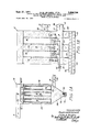
- FIG. 1A is a schematic sectional elevational view of a filtering apparatus embodying the features of this invention with the open end of the filter element(s) at the top;
- FIG. 1B is a schematic sectional elevational view and plan view of a filtering apparatus embodying the features of this invention with the open end of the filter element(s) at the bottom;
- FIG. 1C is a perspective view paratus shown in FIG. 1B;
- FIG. 2 is a schematic sectional elevational view of a portion of the filter apparatus shown in FIG. 1A with enlarged detail of the construction at the upper end portion of the filter tube section, showing the means for generating the pulse of high pressure gas for passage downwardly from the upper end portion of the filter tube; and
- FIG. 3 is a schematic sectional elevational view, similar to that of FIG. 2, showing a modification in the construction for generation of the jet burst of high pressure gas for filter cake removal.
- the filter apparatus comprises an enclosed filter housing 10 subdivided by a horizontally disposed cell plate 12 into an upper clean gas plenum chamber 14 and a lower inlet plenum chamber 16 into which the gaseous material 18 to be processed for removal of suspended solids 20 is introduced through an inlet opening 22 in communication with the inlet plenum chamber 16.
- the lower end portion of the inlet plenum chamber is formed with convergent walls 24 to define a hopper 26 of a section of the apfor collection of the solid particles which fall gravitationally when removed from the filter element surfaces.
- a screw conveyor 28 operates in the trough 30 in the bottom of the hopper 26 for displacement of collected solids from the apparatus.
- Other means such as a rotary air lock, may be used for removal of collected solids.
- An outlet opening 32 communicates the clean gas plenum chamber 14 with the exhaust 9 of clean gas into the atmosphere or the exhaust of clean gas as a process of re-processing gas.
- one or more vertically disposed filter elements 34 Suspended into the inlet plenum chamber 16 are one or more vertically disposed filter elements 34 in the form of elongate porous members, such as stockings or bags preferably formed of felted fabrics of such fibers as cotton, silk, hemp or other natural fibers, or glass, asbestos or the like inorganic fibers, or Orlon, Dacron or the like man-made fibers, or combinations thereof, or woven fabrics of such fibers as cotton, silk, hemp or other natural fibers or man-made fibers, or glass, asbestos or the like inorganic fibers or combinations thereof, but it is further preferred to fabricate the filter tube bag of fibrous fabrics characterized by good wear resistance, good chemical resistance and of fibers which are resistant to high temperatures to enable use in the treatment of gases exhausted at high temperature from such chemical operations as cement plants, aluminum plants, etc.
- the tubular filter member is closed at its lower end and is usually retained in its tubular shape by means of a suitable internal support, such as an open tubular frame 36 formed of wire
- Each filter tube bag is removably suspended from the cell plate 12 by a tubular section 40 fixed to one side of the cell plate 12 with an opening 42 through the cell plate.
- the tubular member is dimensioned to receive the upper open end portion of the filter tube 34 in telescoping relationship thereabout and it is secured in the assembled relation about the tubular section, as by means of a clamp 44.
- a source of primary gas in the form of a nozzle 46 with orifice 62 having diameters such as A5" to 1" in diameter for example and connected at its upper end to a source of supply of high pressure gas with suitable valve means 48 and controls for regulating the frequency and duration of burst of the high pressure primary gas to the nozzle 46.
- nozzle sections 50 and 52 concentrically arranged about the nozzle 46 are two or more nozzle sections 50 and 52 each of increasing diameter to provide an annular space 54 between the nozzle 46 and the nozzle section 50 which is open at its upper end for the flow therethrough of secondary gas and an annular space 56 between the nozzle sections 50 and 52, which is also open at its upper end for the flow therethrough of tertiary gas, etc.
- the nozzle section 50 is provided at its lower end with a tubular section which could be a converging section by extension of the converging upper walls, as illustrated at 80 axially aligned with the nozzle 46 but with the passage through the throat 60 being of larger dimension than the orifice 62 and spaced therefrom by an amount to enable the spreading cone of the jet of primary gas from the orifice 62 to flow in close proximity to the interior wall of the nozzle throat at 60 to generate a pumping action as the burst of gas issues from the orifice 62 for passage through the aligned nozzle or venturi section.
- the secondary gas is drawn through the annular space 54 for addition to the primary gas passing through the throat 60 to generate a burst of gas having greater force and effect for issuance from the end 68 of the nozzle section.
- the filter apparatus comprises an upside down filter device embodying the features of the invention including an enclosed filter housing 11 subdivided by a cell plate into a horizontally disposed clean gas filter element plenum l3 and a dirty gas plenum chamber 19 into which the gaseous material 17 to be processed for removal of suspended solids 21 is introduced through an inlet opening 23 in communication with the dirty gas plenum chamber 19.
- the lower end portion of the dirty plenum chamber is formed with a series of screw conveyor troughs 25 with cross screw conveyors 27 to collect the solid particles which wall gravitationally when removed from the filter element surfaces.
- Another screw conveyor 29 operates in the trough 31 to provide an air tight plug seal at extension 33 for displacement of collected solids from the apparatus.
- An outlet opening 37 communicates with the clean gas filter element plenum 13 with the exhaust 39 of clean gas into the atmosphere or the exhaust of clean gas as a process or reprocessing gas from duct 41.
- one or more vertically disposed filter elements 35 Suspended into the dirty air plenum chamber 19 are one or more vertically disposed filter elements 35 in the form of elongate porous members, such as stockings preferably formed of felted fabrics of such fibers as cotton, silk, hemp or other natural fibers, or rayon, nylon, Dacron or the like synthetic organic fibers, or glass, asbestos or the like inorganic fibers, or combinations thereof, or woven fabrics of such fibers as cotton, silk, hemp or other natural fibers or rayon, nylon, Dacron or the like manmade fibers, glass, asbestos or the like inorganic fibers or combinations thereof, but it is further preferred to fabricate the filter tube of fibrous fabrics characterized by good wear resistance, good chemical resistance, and of fibers which are resistant to high temperatures to enable use in the treatment of gases exhausted at high temperature from such chemical operations as cement plants, aluminum plants, etc.
- the tubular filter member is closed at its upper end and is usually retained in its tubular shape by means of a suitable internal support, such as an open tubular frame
- Each filter element is removably attached to the horizontally disposed cell plate defining the clean gas plenums 13 by a tubular section 45 at opening 47.
- the tubular member is dimensioned to receive the lower open end portion of the filter tube 35 in telescoping relationship thereabout and it is secured in the assembled relation about the tubular section 45 as by means of a clamp 49.
- a source of primary gas in the form of a nozzle 51 with orifice 53 having diameters such as A" to 1" in diameter for example and connected at its lower end to a source of supply of high pressure gas with suitable valve means 55 and controls for regulating the frequency and duration of burst of the high pressure primary gas to the nozzle 51.
- concentrically arranged about the nozzle 51 are two or more nozzles and a venturi section 57 and 59, each of increasing diameter to provide an annular space 61a between the nozzle 51 and the nozzle section 57 which is open at its lower end for the flow therethrough of secondary gas and an annular space 63 between the nozzle and venturi sections 57 and 59 which is also open at its lower ends for the flow therethrough of tertiary gas, etc.
- the nozzle section 57 is provided at its upper end with a converging section 65 axially aligned with the nozzle 51 but with the passage through the throat 67 being of larger dimension than the orifice 53 and spaced therefrom by an amount to enable the spreading cone of the jet of primary gas from the orifice 53 to fiow in close proximity to the interior wall of the nozzle throat at 67 to generate a pumping action as the burst of gas issues from the orifice 53 for passage through the aligned nozzle section.
- the secondary gas is drawn through the annular space 61a for addition to the primary gas passing through the throat 67 to generate a burst of gas having greater force and effect for issuance from the end 69 of the nozzle section.
- third, fourth, etc. concentrically arranged nozzles may be provided with increasing spaced relationship about the described nozzles to provide the necessary spaces for the access to quaternary or quinterary gas with the lower ends constructed to define additional throat sections with outlets from previous nozzles thereby further to increase the force of gas issuing from the multiple nozzle an venturi arrangement into the filter tube.
- the pressure of the primary gas should be higher than atmospheric pressure, such as within the range of 20200 psi. and preferably within the range of 50-125 p.s.i., with a time of burst measurable in milli-seconds, such as from to 250 milli-seconds, and preferably to 100 milli-seconds.
- FIG. 3 A triple nozzle and venturi sequence in the multiple jet arrangement of this invention is illustrated in FIG. 3 by modification of the construction shown in FIG. 2 to add a nozzle 80 of greater diameter than the nozzle 50 but less than that of the open end of the filter tube 34 to provide an annular space 82 between section 52 and section 80 through which quaternary gas can flow for admixture with the burst of gas issuing from the previous nozzle section 80.
- the final section is preferably a complete venturi in critical vertical and axial alignment (staged) with the prior or previous nozzles whereby the divergent jet 88 of gas flows in close proximity to the walls of the final venturi, creating a reduction in absolute pressure and causing a pumping action for drawing quaternary gas into the previous high energy gas stream.
- the duration of burst of high pressure gas can be greatly decreased and the amount of high pressure gas required to generate the gas burst can also be materially reduced, as can be illustrated by the following comparison between an apparatus currently being marketed utilizing the principles disclosed in Reissue Pat. No. 24,954 similar to, but not of identical construction as that in the disclosure, and operated in accordance with the practice of this invention as illustrated in FIG. 2.
- Such reduction in duration of burst and in the amount of high pressure gas required to eflect satisfactory cleaning contributes importantly to the decreased cost and expense in the operation of the filter device embodying the features of this invention.
- the increased force of the burst provides for more effective removal of the filter cake from the walls of the filter tubes with the result that the filter device of this invention does operate at lower pressure drop across the filter medium for removal of equivalent amounts of material, thereby to provide a further important contribution to the savings in cost of dust and dirt removal.
- test collector
- FIG URE 2 Orifice meter Pressure drop Pressure drop, across a bag, across thiniblu before and before and floor, before and after pulse during pulse after pulse Time Before After Before During Before After Initial 4.0 1.5 Minutes: 2 1 7H" 4. l5 4. 25 0 2. l 1. (3 4.15 4. 25 t) 1 1.55 4. 2 4. 3 I) 2. 15 l. t5 4. .l 4. 3 U 2. 15 l. 6 4. 2 4. 3 (l 2. l 1. ti 4. .2 4. 3 l 1.. 15 1.65 4.15 4.25 +.1 2.1? 1.65 4.15 4. 25 +.l 2. 2 l. 7 4.15 4. 25 +.l 2. 25 1.7 4. 15 4. 25 1 2. 25 1. B5 4.15 4...
- the unit of this invention operates at considerably lesser pressure difierential through the filter medium which enables filtration to be effected either in greater gas volumes or with less power and thereby to increase the efficiency of operation of the unit.
- Average filter drag with the unit of this invention gave a value of 0.21 inch W.G./c.f.m. as compared to an average filter drag of 0.347 inch W.G./ c.f.m. for the structure representative of the Reissue patent.
- Use was made of 60% as much pressurized gas with the apparatus of FIG. 2 thereby to provide a -40% savings in compressed air as well as a savings in filter drag.
- the graphs illustrate comparative tests showing pressure drop with respect to time during the continuous operation of the respective units with fine air cleaner test dust suspended in air to be filtered with the unit representing the practice of this invention and illustrated by the curve having the lower values, operating with an air pulse of 40-45 milliseconds of p.s.i. air using a nozzle having an orifice of 0.339 inch diameter and with the unit representative of the reissue patent operating with air pressure of psi. a duration of pulse of milliseconds and with the 0.25 diameter orifice.
- An apparatus for gaseous filtration to elfect removal of suspended solids including a housing, divided into a dirty gas section and a filtered gas section by means of a tube sheet, said housing containing two or more filter tubes, the open upper end of each filter tube being attached to said tube sheet, said housing including a dirty gas inlet duct, a filtered gas outlet duct, a hopper, means for removing collected solid matter from said hopper without loss of filter gas flow, means for flowing gaseous medium containing suspended solids to be removed through the walls of the filter tubes in normal filter flow from the outside to the interior of the filter tubes whereby solids separated from the gaseous medium collect on the outer walls of the filter tubes as a filter cake, the improvement wherein collected solids are removed from the surface of a portion of the filter tubes without stopping normal filter flow comprising a primary nozzle extending into the filter tube having its outlet upstream of the open end of the filter tube as measured by normal filter flow and in endwise alignment therewith, a source of primary pressurized gas connected with the
- each nozzle other than the primary nozzle communicates directly with atmospheric air or other low pressure gas source which is drawn through each said nozzle or venturi by the reaction to the burst of air or gas projected into each said nozzle or venturi from the preceding nozzle.
- An apparatus for gaseous filtration to effect removal of suspended solids including a housing, divided into a dirty gas section and a filtered gas section by means of a horizontally disposed clean gas filter plenum chamher, said housing containing two or more filter tubes, the open lower end of each filter tube being attached to said horizontally disposed clean gas plenum chamber, said housing including a dirty gas inlet duct, a filtered gas outlet duct, a hopper, means for removing collected solid matter from said hopper or container without loss of filter gas flow, means for flowing gaseous medium containing suspended solids to be removed through the walls of the filter tubes in normal filter fiow from the outside to the interior of the filter tubes whereby solids separated from the gaseous medium collect on the outer walls of the filter tubes as a filter cake, the improvement wherein collected solids are removed from the surfaces of a portion of the filter tubes without stopping normal filter flow comprising a primary nozzle for directing a stream of gas upwardly into the tube and extending upstream through the open end of the tube in
- An apparatus as claimed in claim 5 in which the total number of nozzles above the primary nozzle is between two and six.
- each nozzle other than the primary nozzle communicates directly with atmospheric air or other low pressure gas source which is drawn through each said nozzle or venturi by the reaction to the burst of air or gas projected into each said nozzle or venturi from the preceding nozzle.
Abstract
APPARATUS FOR GASEOUS FILTRATION TO EFFECT REMOVAL OF SUSPENDED SOLIDS IN WHICH USE IS MADE OF ELONGATE FILTER ELEMENTS HAVING AN OPEN END AND MEANS FOR FLOWING GASEOUS MEDIUM CONTAINING THE SUSPENDED SOLIDS THROUGH THE WALLS OF THE FILLER ELEMENT WHEREBY SEPARATED SOLIDS COLLECT ON THE OUTER WALL OF THE FILTER ELEMENT AS A FILTER CAKE AND IN WHICH USE IS MADE OF A GAS NOZZLE IN ENDWISE ALIGNMENT AND COLINEAR ALIGNMENT WITH ONE OR MORE AUXILLIARY NOZZLES FOLLOWED BY A VENTURI FOR RELEASING OR GENERATING A BURST OF GAS OF HIGH PRESSURE AND INCREASING VOLUME IN THE INTERIOR OF THE FILTER TUBE BEING CLEANED, TO EFFECT REMOVAL OF SOLIDS COLLECTED ON THE WALLS OF THE TUBE, WITHOUT STOPPING TOTAL FILTER FLOW.
Description
3,606,736 ASEOUS p 1971 R. M. LELIAERT ETA!- APPARATUS FOR FILTERING SUSPENDED SOLIDS FROM G MEDIUM AND FOR REMOVAL OF FILTER CAKE FROM FILTER ELEMENTS Filed June 16, 1969 3 Sheets-Sheet 1 I N VEN TOPS Raymund/14 [elz'aeri' l .S a b ydcA ny er Sept. 21, 1971 LEUAERT ETAL 3,606,736
APPARATUS FOR FILTERING SUSPENDED SOLIDS FROM GASEOUS MEDIUM AND FOR REMOVAL OF FILTER CAKE FROM FILTER ELEMENTS Filed June 16, 1969 3 Sheets-Sheet 2 y" I l 1 Sept. 21, 1971 LEUAERT EI'AL 3,606,736
APPARATUS FOR FILTERING SUSPENDED SOLIDS FROM GASEOUS MEDIUM AND FOR REMOVAL OF FILTER CAKE FROM FILTER ELEMENTS Filed June 16, 1969 3 Sheets-Sheet I5 6 mwbsumuu I 2 6 sfim 2 w m5 2 I I /Y8 w V L1 d flw 4 5 rv w L E NH w l I |||1|| 1 I II I w w m x M awfiog Jr 5 IV V I H R D w Ir 1 ii E z I u M M 5 66 O u m 511%-- y w 4 United States Patent U.S. Cl. 55-302 8 Claims ABSTRACT OF THE DISCLOSURE Apparatus for gaseous filtration to effect removal of suspended solids in which use is made of elongate filter elements having an open end and means for flowing gaseous medium containing the suspended solids through the walls of the filter element whereby separated solids collect on the outer wall of the filter element as a filter cake and in which use is made of a gas nozzle in endwise alignment and colinear alignment with one or more auxiliary nozzles followed by a venturi for releasing or generating a burst of gas of high pressure and increasing volume in the interior of the filter tube being cleaned, to effect removal of solids collected on the walls of the tube, without stopping total filter flow.
This invention relates to the treatment of gases and vapors for the removal of solids suspended therein. It relates more particularly to a method and apparatus for filtering air or gaseous medium for the removal of dust, dirt and the like solid particles suspended therein.
With reference to the well known processes of filtration wherein use is made of one and preferably a plurality of porous filter tubes or bags through which the gaseous medium to be filtered is passed from an ingoing side to the opposite outgoing side, the solids separated from the gaseous medium build up on the walls of the ingoing side of the tube to form a filter cake. As the filter cake builds up in thickness, the pressure drop across the filter medium increases whereupon it ultimately becomes necessary to effect removal of the filter cake or a greater portion thereof for most efficient operation.
In the past, this has been accomplished in a number of ways. One simple technique has been to make use of a shaking device from which the filter bags or tubes are suspended and operated periodically to shake the bags to loosen the filter cake collected on the surfaces thereof. The dislodged dust or dirt falls gravitationally through the filter chamber to a collecting chamber at the bottom from which it is removed. In order to permit the solids dislodged from the surfaces of the filter tubes to fall gravitationally to the collector at the bottom, it has been necessary to stop filter flow of the dust laden gases, at least in the sections or compartments in which the bags are being cleaned.
In the attempt to achieve more effective removal of the solids entrapped within the walls or pores of the filter bag while dislodging solids forming the filter cake, use has also been made of a process identified as a back washing" technique wherein the flow of gaseous medium is reversed for How back through the filter surface from the outgoing side to the ingoing side. This back washing operation is intended to dislodge the filter cake and blow the collected solids from within the pores of the filter surface with corresponding reduction in pressure drop across the filter medium. Again, the back washing process requires that the normal filter flow be terminated in a section or compartment during the back washing operation whereby numerous valves and controls are required for regulating gaseous flow and for proper sequencing of the various operations.
3,606,736 Patented Sept. 21, 1971 More recently, as described in the Church Pat. Re. 24,954, the need for stopping filter flow in isolated compartments during filter cake removal has been eliminated by the intermittent use of a jet of gas across the open mouths of each of the outgoing side of a portion of the filter tubes in which the jet is applied at a pressure substantially greater than that of the stream of gas to be filtered. As a result, a counterfiow is established which generates a sweeping action distending and snapping the filter element, effective to dislodge the filter cake and clean the pores to the extent that pressure drop across the filter surface is markedly reduced. The described removal of solids collected on the filter surface can be effected without interruption of the total filter flow although part of the flow of the filtering gas is temporarily reversed by the jet action. Thus, the described solids removal is generated without the need for the compartmentation, piping and valving systems characteristic of the back washing or shaking operation since the need is only for intermittent release of the burst of high pressure gas.
As in the other systems, the solids dislodged from the filter surface are capable of falling gravitationally to a collecting section from which the solids are removed.
The described filtration system is still subject to a number of deficiencies, such as the use of an excessive amount of high pressure gas, exacting control of distance and dimensions of the various parts for the generation of an effective jet stream, and a characteristic of the system is in the operation at relatively high pressure differentials with corresponding high filter drag, which is a measure of efficiency of operation.
It is an object of this invention to provide a method and apparatus which represents a marked improvement in the jet principle for removal of solids collected on the surfaces of filter elements with considerable savings in pressurized gas with less filter drag, and it is a related object to provide a filtering system of the type described which operates at lower levels of pressure drop across the filter surface and with improved operating efficiency.
These and other objects and advantages of this invention will hereinafter appear and, for purposes of illustration, but not of limitation, embodiments of the invention are shown in the accompanying drawings, in which:
FIG. 1A is a schematic sectional elevational view of a filtering apparatus embodying the features of this invention with the open end of the filter element(s) at the top;
FIG. 1B is a schematic sectional elevational view and plan view of a filtering apparatus embodying the features of this invention with the open end of the filter element(s) at the bottom;
FIG. 1C is a perspective view paratus shown in FIG. 1B;
FIG. 2 is a schematic sectional elevational view of a portion of the filter apparatus shown in FIG. 1A with enlarged detail of the construction at the upper end portion of the filter tube section, showing the means for generating the pulse of high pressure gas for passage downwardly from the upper end portion of the filter tube; and
FIG. 3 is a schematic sectional elevational view, similar to that of FIG. 2, showing a modification in the construction for generation of the jet burst of high pressure gas for filter cake removal.
As illustrated in FIG. 1A, the filter apparatus comprises an enclosed filter housing 10 subdivided by a horizontally disposed cell plate 12 into an upper clean gas plenum chamber 14 and a lower inlet plenum chamber 16 into which the gaseous material 18 to be processed for removal of suspended solids 20 is introduced through an inlet opening 22 in communication with the inlet plenum chamber 16.
The lower end portion of the inlet plenum chamber is formed with convergent walls 24 to define a hopper 26 of a section of the apfor collection of the solid particles which fall gravitationally when removed from the filter element surfaces. A screw conveyor 28 operates in the trough 30 in the bottom of the hopper 26 for displacement of collected solids from the apparatus. Other means, such as a rotary air lock, may be used for removal of collected solids.
An outlet opening 32 communicates the clean gas plenum chamber 14 with the exhaust 9 of clean gas into the atmosphere or the exhaust of clean gas as a process of re-processing gas.
Suspended into the inlet plenum chamber 16 are one or more vertically disposed filter elements 34 in the form of elongate porous members, such as stockings or bags preferably formed of felted fabrics of such fibers as cotton, silk, hemp or other natural fibers, or glass, asbestos or the like inorganic fibers, or Orlon, Dacron or the like man-made fibers, or combinations thereof, or woven fabrics of such fibers as cotton, silk, hemp or other natural fibers or man-made fibers, or glass, asbestos or the like inorganic fibers or combinations thereof, but it is further preferred to fabricate the filter tube bag of fibrous fabrics characterized by good wear resistance, good chemical resistance and of fibers which are resistant to high temperatures to enable use in the treatment of gases exhausted at high temperature from such chemical operations as cement plants, aluminum plants, etc. The tubular filter member is closed at its lower end and is usually retained in its tubular shape by means of a suitable internal support, such as an open tubular frame 36 formed of wire screening or the like rigid, highly foraminous material.
Each filter tube bag is removably suspended from the cell plate 12 by a tubular section 40 fixed to one side of the cell plate 12 with an opening 42 through the cell plate. The tubular member is dimensioned to receive the upper open end portion of the filter tube 34 in telescoping relationship thereabout and it is secured in the assembled relation about the tubular section, as by means of a clamp 44.
Extending downwardly into the opening beyond the upper end of the filter tube is a source of primary gas in the form of a nozzle 46 with orifice 62 having diameters such as A5" to 1" in diameter for example and connected at its upper end to a source of supply of high pressure gas with suitable valve means 48 and controls for regulating the frequency and duration of burst of the high pressure primary gas to the nozzle 46.
concentrically arranged about the nozzle 46 are two or more nozzle sections 50 and 52 each of increasing diameter to provide an annular space 54 between the nozzle 46 and the nozzle section 50 which is open at its upper end for the flow therethrough of secondary gas and an annular space 56 between the nozzle sections 50 and 52, which is also open at its upper end for the flow therethrough of tertiary gas, etc.
The nozzle section 50 is provided at its lower end with a tubular section which could be a converging section by extension of the converging upper walls, as illustrated at 80 axially aligned with the nozzle 46 but with the passage through the throat 60 being of larger dimension than the orifice 62 and spaced therefrom by an amount to enable the spreading cone of the jet of primary gas from the orifice 62 to flow in close proximity to the interior wall of the nozzle throat at 60 to generate a pumping action as the burst of gas issues from the orifice 62 for passage through the aligned nozzle or venturi section. Thus the secondary gas is drawn through the annular space 54 for addition to the primary gas passing through the throat 60 to generate a burst of gas having greater force and effect for issuance from the end 68 of the nozzle section.
As illustrated in FIGS. 1B and 1C, the filter apparatus comprises an upside down filter device embodying the features of the invention including an enclosed filter housing 11 subdivided by a cell plate into a horizontally disposed clean gas filter element plenum l3 and a dirty gas plenum chamber 19 into which the gaseous material 17 to be processed for removal of suspended solids 21 is introduced through an inlet opening 23 in communication with the dirty gas plenum chamber 19.
The lower end portion of the dirty plenum chamber is formed with a series of screw conveyor troughs 25 with cross screw conveyors 27 to collect the solid particles which wall gravitationally when removed from the filter element surfaces. Another screw conveyor 29 operates in the trough 31 to provide an air tight plug seal at extension 33 for displacement of collected solids from the apparatus.
An outlet opening 37 communicates with the clean gas filter element plenum 13 with the exhaust 39 of clean gas into the atmosphere or the exhaust of clean gas as a process or reprocessing gas from duct 41.
Suspended into the dirty air plenum chamber 19 are one or more vertically disposed filter elements 35 in the form of elongate porous members, such as stockings preferably formed of felted fabrics of such fibers as cotton, silk, hemp or other natural fibers, or rayon, nylon, Dacron or the like synthetic organic fibers, or glass, asbestos or the like inorganic fibers, or combinations thereof, or woven fabrics of such fibers as cotton, silk, hemp or other natural fibers or rayon, nylon, Dacron or the like manmade fibers, glass, asbestos or the like inorganic fibers or combinations thereof, but it is further preferred to fabricate the filter tube of fibrous fabrics characterized by good wear resistance, good chemical resistance, and of fibers which are resistant to high temperatures to enable use in the treatment of gases exhausted at high temperature from such chemical operations as cement plants, aluminum plants, etc. The tubular filter member is closed at its upper end and is usually retained in its tubular shape by means of a suitable internal support, such as an open tubular frame 43 formed of wire screening or the like rigid, highly foraminous material.
Each filter element is removably attached to the horizontally disposed cell plate defining the clean gas plenums 13 by a tubular section 45 at opening 47. The tubular member is dimensioned to receive the lower open end portion of the filter tube 35 in telescoping relationship thereabout and it is secured in the assembled relation about the tubular section 45 as by means of a clamp 49.
Extending upwardly into the opening beyond the lower end of the filter tube is a source of primary gas in the form of a nozzle 51 with orifice 53 having diameters such as A" to 1" in diameter for example and connected at its lower end to a source of supply of high pressure gas with suitable valve means 55 and controls for regulating the frequency and duration of burst of the high pressure primary gas to the nozzle 51.
concentrically arranged about the nozzle 51 are two or more nozzles and a venturi section 57 and 59, each of increasing diameter to provide an annular space 61a between the nozzle 51 and the nozzle section 57 which is open at its lower end for the flow therethrough of secondary gas and an annular space 63 between the nozzle and venturi sections 57 and 59 which is also open at its lower ends for the flow therethrough of tertiary gas, etc.
The nozzle section 57 is provided at its upper end with a converging section 65 axially aligned with the nozzle 51 but with the passage through the throat 67 being of larger dimension than the orifice 53 and spaced therefrom by an amount to enable the spreading cone of the jet of primary gas from the orifice 53 to fiow in close proximity to the interior wall of the nozzle throat at 67 to generate a pumping action as the burst of gas issues from the orifice 53 for passage through the aligned nozzle section. Thus the secondary gas is drawn through the annular space 61a for addition to the primary gas passing through the throat 67 to generate a burst of gas having greater force and effect for issuance from the end 69 of the nozzle section.
It will be apparent that third, fourth, etc. concentrically arranged nozzles may be provided with increasing spaced relationship about the described nozzles to provide the necessary spaces for the access to quaternary or quinterary gas with the lower ends constructed to define additional throat sections with outlets from previous nozzles thereby further to increase the force of gas issuing from the multiple nozzle an venturi arrangement into the filter tube.
Such accentuation of the gas burst even with a substantial decrease in the length of burst enables considerable savings in the amount of high pressure gas employed while decreasing the amount of time taken up by the cleaning cycle. The increase in the force of burst whereby the removal of solids from the pores of the filter tube or filter surface is more complete enables operation with lower pressure drop and corresponding decrease in filter drag, all of which adds up to a more efficient and effective operation of filtration.
The pressure of the primary gas should be higher than atmospheric pressure, such as within the range of 20200 psi. and preferably within the range of 50-125 p.s.i., with a time of burst measurable in milli-seconds, such as from to 250 milli-seconds, and preferably to 100 milli-seconds.
A triple nozzle and venturi sequence in the multiple jet arrangement of this invention is illustrated in FIG. 3 by modification of the construction shown in FIG. 2 to add a nozzle 80 of greater diameter than the nozzle 50 but less than that of the open end of the filter tube 34 to provide an annular space 82 between section 52 and section 80 through which quaternary gas can flow for admixture with the burst of gas issuing from the previous nozzle section 80.
The final section is preferably a complete venturi in critical vertical and axial alignment (staged) with the prior or previous nozzles whereby the divergent jet 88 of gas flows in close proximity to the walls of the final venturi, creating a reduction in absolute pressure and causing a pumping action for drawing quaternary gas into the previous high energy gas stream.
It will be apparent from the foregoing that the sequence can be continued to increase the number of nozzles aligned further to magnify the force of the burst of gas introduced into the filter tubes but it has been found that a point of diminishing return is encountered when the number of nozzles followed by a venturi in sequence exceeds about six and best results are generally secured with two, three or four nozzles followed by a venturi.
Because of the augmentations of the burst of gas issuing from the last of the sequence of nozzles and venturi, in accordance with the practice of this invention, the duration of burst of high pressure gas can be greatly decreased and the amount of high pressure gas required to generate the gas burst can also be materially reduced, as can be illustrated by the following comparison between an apparatus currently being marketed utilizing the principles disclosed in Reissue Pat. No. 24,954 similar to, but not of identical construction as that in the disclosure, and operated in accordance with the practice of this invention as illustrated in FIG. 2. Such reduction in duration of burst and in the amount of high pressure gas required to eflect satisfactory cleaning contributes importantly to the decreased cost and expense in the operation of the filter device embodying the features of this invention.
Further, the increased force of the burst provides for more effective removal of the filter cake from the walls of the filter tubes with the result that the filter device of this invention does operate at lower pressure drop across the filter medium for removal of equivalent amounts of material, thereby to provide a further important contribution to the savings in cost of dust and dirt removal.
For purposes of comparison, use was made of the same filter bags in the same amounts and in the same arrangement in apparatus operating under the same conditions of dust in gas to be filtered and under the same conditions of rate of feed whereby substantially the same volume of gas containing substantially the same amount of the same dust or dirt was processed in equivalent time. Differences were eflected only in the gas pressure required and in the duration of the initial burst for operating the respective units under optimum conditions.
Gas at 95 p.s.i. was used in the apparatus corresponding to Re. 24,954, While 75 psi. was used in the apparatus of the invention as represented by FIG. 2. The former apparatus used an air orifice A" diameter and a pulse duration of 100 milli-seconds, while the apparatus of this invention used an orifice 0.339" with a pulse duration of 40-45 seconds. In each case, each of three rows of bags was pulsed every minute and observations taken of relevant data every five minutes.
As a measurement of efficiency, calculations were made to determine filter drag, as determined by dividing the pressure drop in inches W.G. with the gas to cloth ratio in the filter unit under test.
REISSUE PATENT NO. 24,954.
()riliee meter Single bag Pressure drop pressure drop, pressure drop, across thirnble before and before and floor before and ttcr pulse during pulse after pulse llefoi e Time After Before During Before After lnitial.. 4.15 28 3.1........ Minutes: 5 4.25 4.45 2.7 .1 2.0 2.1 4.15 4. 5 2. 7 -.1 I5. 0 2.15
4 25 t 4 d U (l 3 3 2 45 4 l5 3 3 25 1 l 5 2 b 1 Minus sign=lressuro drop in backwash direction. Norus ltvg. e.f.1n.=547, air-cloth ratio 9.8 to l. glzjttfi (Fine air cleaner test dust.) Avg. collector pressure drop before p'llsiug 3.79 W11. Avg. collector pressure drop after pulsing 2.917 WA Filter drag before pulsing O.3:l'/c.f.rn., alter (J.3Uje.i.rn. Avg. tiller drag 0. 'htTfi'ofan. Orifice ureter press. Drop is a. measure of input elm. to the Dust loading 3.78
test collector.
FIG URE 2 Orifice meter Pressure drop Pressure drop pressure drop, across a bag, across thiniblu before and before and floor, before and after pulse during pulse after pulse Time Before After Before During Before After Initial 4.0 1.5 Minutes: 2 1 7H" 4. l5 4. 25 0 2. l 1. (3 4.15 4. 25 t) 1 1.55 4. 2 4. 3 I) 2. 15 l. t5 4. .l 4. 3 U 2. 15 l. 6 4. 2 4. 3 (l 2. l 1. ti 4. .2 4. 3 l 1.. 15 1.65 4.15 4.25 +.1 2.1? 1.65 4.15 4. 25 +.l 2. 2 l. 7 4.15 4. 25 +.l 2. 25 1.7 4. 15 4. 25 1 2. 25 1. B5 4.15 4.. +.1 2.1.5 1.7 4.15 4. 25 +.2 2.3 1.7 4.15 4. 25 2 2. 3 1. 75 4.15 4. .25 2 2. 35 1.75 4.15 4. 25 +.2 2.4 1.75 4.15 4-. 25 3 2 45 1.8 4.] 4.2 +.2 .245 1.8 4. 1 4. 2 2 2. 5 l. 8 4. 1 4. '2 .1 2. 5 1. 8 4.1 4. 2 2 2. 45 1. 8 4. l 4. 2 2 2. 5 1. 8 4.1 4.2 +.2 2.5 1.85 4. 1 4. 2 2 l. 85 4. 1 4. 2 2 1. 85
I V .f.m.=550, air-cloth ratio 93:1. Dust loading 3.74 gr 'ft (Fine air cleaner test dust.) Avg. collector pressure drop before pulsing 2.32 W.(l. Avg. collector pressure drop after pulsing 1.78 W11. Filter drag before pulsing 0.24"/e.f.1u. Filter drag after pulsing 0.18 ('.f. n 1. Avg. filter drug0.2l".i'r.f.n1., or 60.5% of the filter drug for Re. 24,954. ()rllree meter press drop is a measure of input c.f.ni. to the test collector.
OF oPERM' ON.
It will be noted from the foregoing tabulations that the unit of this invention operates at considerably lesser pressure difierential through the filter medium which enables filtration to be effected either in greater gas volumes or with less power and thereby to increase the efficiency of operation of the unit. Average filter drag with the unit of this invention gave a value of 0.21 inch W.G./c.f.m. as compared to an average filter drag of 0.347 inch W.G./ c.f.m. for the structure representative of the Reissue patent. Use was made of 60% as much pressurized gas with the apparatus of FIG. 2 thereby to provide a -40% savings in compressed air as well as a savings in filter drag.
The graphs illustrate comparative tests showing pressure drop with respect to time during the continuous operation of the respective units with fine air cleaner test dust suspended in air to be filtered with the unit representing the practice of this invention and illustrated by the curve having the lower values, operating with an air pulse of 40-45 milliseconds of p.s.i. air using a nozzle having an orifice of 0.339 inch diameter and with the unit representative of the reissue patent operating with air pressure of psi. a duration of pulse of milliseconds and with the 0.25 diameter orifice.
It will be noted from the graphs that the pressure drop is of a constant lower value with the apparatus of this invention as compared to the pressure drop across the filter medium of the prior art device, operating under the same load conditions.
It will be understood that changes may be made in the details of construction, arrangement and operation without departing from the spirit of the invention, especially as defined in the following claims.
We claim:
1. An apparatus for gaseous filtration to elfect removal of suspended solids, including a housing, divided into a dirty gas section and a filtered gas section by means of a tube sheet, said housing containing two or more filter tubes, the open upper end of each filter tube being attached to said tube sheet, said housing including a dirty gas inlet duct, a filtered gas outlet duct, a hopper, means for removing collected solid matter from said hopper without loss of filter gas flow, means for flowing gaseous medium containing suspended solids to be removed through the walls of the filter tubes in normal filter flow from the outside to the interior of the filter tubes whereby solids separated from the gaseous medium collect on the outer walls of the filter tubes as a filter cake, the improvement wherein collected solids are removed from the surface of a portion of the filter tubes without stopping normal filter flow comprising a primary nozzle extending into the filter tube having its outlet upstream of the open end of the filter tube as measured by normal filter flow and in endwise alignment therewith, a source of primary pressurized gas connected with the primary nozzle, means for regulating the fiow of pressurized gas to provide short bursts of pressurized gas to the primary nozzle, additional nozzles upstream of the primary nozzle as measured by normal filter flow and axially aligned one with another and the primary nozzle, each nozzle having its upstream end portion nesting in the downstream end portion of the adjacent upstream nozzle in telescoping relation, the downstream end portion of each nozzle being dimensioned to be larger in cross-section than the portion of the downstream nozzle nested therein to provide a spaced relation between the telescoping walls of the nozzles with the telescoping portion of the downstream nozzle axially spaced from the upstream end of the upstream nozzle by an amount whereby the gas issuing from the nozzle flows into close proximity to the wall of the respective upstream nozzle as it spreads to form a cone, the downstream end of each of the additional nozzles being in flow communication with the filtered gas outlet duct, whereby the final burst of gas issuing from the last nozzle into the interior of the filter tube includes the initial jet of high pressure 12 gas projected from the primary nozzle plus additional increments of air drawn in by each succeeding nozzle.
2. An apparatus as claimed in claim 1 in which the total number of nozzles below the primary nozzle is between two and six.
3. An apparatus as claimed in claim 1 in which the total number of nozzles below the primary nozzle is between two and four.
4. An apparatus as claimed in claim 1 in which each nozzle other than the primary nozzle communicates directly with atmospheric air or other low pressure gas source which is drawn through each said nozzle or venturi by the reaction to the burst of air or gas projected into each said nozzle or venturi from the preceding nozzle.
5. An apparatus for gaseous filtration to effect removal of suspended solids, including a housing, divided into a dirty gas section and a filtered gas section by means of a horizontally disposed clean gas filter plenum chamher, said housing containing two or more filter tubes, the open lower end of each filter tube being attached to said horizontally disposed clean gas plenum chamber, said housing including a dirty gas inlet duct, a filtered gas outlet duct, a hopper, means for removing collected solid matter from said hopper or container without loss of filter gas flow, means for flowing gaseous medium containing suspended solids to be removed through the walls of the filter tubes in normal filter fiow from the outside to the interior of the filter tubes whereby solids separated from the gaseous medium collect on the outer walls of the filter tubes as a filter cake, the improvement wherein collected solids are removed from the surfaces of a portion of the filter tubes without stopping normal filter flow comprising a primary nozzle for directing a stream of gas upwardly into the tube and extending upstream through the open end of the tube in endwise alignment therewith, as measured by normal filter fiow, a source of primary pressurized gas connected with the primary nozzle, means for regulating the How of pressurized gas to said nozzle to provide short bursts of pressurized gas to the nozzle, additional nozzles upstream of the primary nozzle as measured, by normal filtering flow and axially aligned one with another and the primary nozzle in the filter tube, each nozzle having its upstream end portion nesting in the downstream end portion of the adjacent upstream nozzle in telescoping relation, the downstream end portion of each nozzle being dimensioned to be larger in cross-section than the portion of the downstream nozzle nested therein to provide a spaced relation between the telescoping walls of the nozzles with the telescoping portion of the downstream nozzle axially spaced from the upstream end portion of the upstream nozzle by an amount whereby the gas issuing from the nozzle flows into close proximity to the wall of the respective downstream nozzle as it spreads into a cone, the downstream end of each of the additional nozzles being in flow communication with the clean gas plenum chamber, whereby the final burst of gas issuing from the last nozzle into the interior of the filter tube includes the initial jet of high pressure gas projected from the primary nozzle plus additional increments of air drawn in by each succeeding nozzle.
6. An apparatus as claimed in claim 5 in which the total number of nozzles above the primary nozzle is between two and six.
7. An apparatus as claimed in claim 5 in which the total number of nozzles above the primary nozzle is between two and four.
8. An apparatus as claimed in claim 5 in which each nozzle other than the primary nozzle communicates directly with atmospheric air or other low pressure gas source which is drawn through each said nozzle or venturi by the reaction to the burst of air or gas projected into each said nozzle or venturi from the preceding nozzle.
(References on following page) 13 14 References Cited FRANK W. LUTTER, Primary Examiner UNITED STATES PATENTS B. NOZICK, Assistant Examiner 1,031,722 7/1912 Leblanc 2301 12 U5, L R
FOREIGN PATENTS 5 55-341 225,059 10/1959 Australia. 248,453 12/1963 Australia.
Applications Claiming Priority (1)
| Application Number | Priority Date | Filing Date | Title |
|---|---|---|---|
| US83353169A | 1969-06-16 | 1969-06-16 |
Publications (1)
| Publication Number | Publication Date |
|---|---|
| US3606736A true US3606736A (en) | 1971-09-21 |
Family
ID=25264667
Family Applications (1)
| Application Number | Title | Priority Date | Filing Date |
|---|---|---|---|
| US833531A Expired - Lifetime US3606736A (en) | 1969-06-16 | 1969-06-16 | Apparatus for filtering suspended solids from gaseous medium and for removal of filter cake from filter elements |
Country Status (10)
| Country | Link |
|---|---|
| US (1) | US3606736A (en) |
| BE (1) | BE752077A (en) |
| BR (1) | BR7019754D0 (en) |
| CA (1) | CA949893A (en) |
| CH (1) | CH526328A (en) |
| DE (1) | DE2029596A1 (en) |
| ES (1) | ES380808A1 (en) |
| FR (1) | FR2052625A5 (en) |
| GB (1) | GB1302447A (en) |
| ZA (1) | ZA703844B (en) |
Cited By (33)
| Publication number | Priority date | Publication date | Assignee | Title |
|---|---|---|---|---|
| US3726066A (en) * | 1970-12-14 | 1973-04-10 | Wheelabrator Frye Inc | Dust collector |
| US3765152A (en) * | 1970-11-04 | 1973-10-16 | Gen Resource Corp | Cleaning of filtering media |
| US3798878A (en) * | 1972-08-18 | 1974-03-26 | Gen Resource Corp | Filter cleaning apparatus |
| US3816978A (en) * | 1971-10-18 | 1974-06-18 | American Air Filter Co | Filter arrangement |
| US3826066A (en) * | 1971-07-16 | 1974-07-30 | Summit Filter Corp | Double-wall filter bag construction |
| US3850594A (en) * | 1971-07-16 | 1974-11-26 | Summit Filter Corp | Filtering method utilizing a double-wall filter bag construction |
| US3853509A (en) * | 1973-05-04 | 1974-12-10 | R Leliaert | Bag type filter device |
| US3891418A (en) * | 1972-12-07 | 1975-06-24 | Fischer Ag Georg | Gas filter |
| US3893833A (en) * | 1972-04-26 | 1975-07-08 | Flex Kleen Corp | Compartmented pulse jet dust collector |
| JPS513476U (en) * | 1974-06-25 | 1976-01-12 | ||
| US4026686A (en) * | 1974-05-11 | 1977-05-31 | Loedige Wilhelm | Vacuum filter for the purification of gaseous materials |
| US4033732A (en) * | 1974-05-02 | 1977-07-05 | Aktiebolaget Svenska Flaktfabriken | Method and apparatus for cleaning fabric filters of bag type or the like |
| EP0002830A2 (en) | 1977-12-27 | 1979-07-11 | Union Carbide Corporation | A wire or cable insulated with a dielectric composition stabilized against water treeing with organo silane compounds and its use |
| US4193780A (en) * | 1978-03-20 | 1980-03-18 | Industrial Air, Inc. | Air filter construction |
| US4247310A (en) * | 1977-07-15 | 1981-01-27 | Gebrueder Buehler Ag | Pneumatic dust extraction |
| US4270935A (en) * | 1977-06-27 | 1981-06-02 | United States Filter Corporation | Filter assembly for high temperature glass fiber filter media |
| US4272262A (en) * | 1979-09-27 | 1981-06-09 | American Air Filter Company, Inc. | Gas-separation filter device |
| US4278454A (en) * | 1979-05-29 | 1981-07-14 | Wehr Corporation | Filter apparatus with reverse flow cleaning |
| US4632680A (en) * | 1985-10-28 | 1986-12-30 | Carter-Day Co. | Planar sided air shaping inserts for filter bags |
| US5094673A (en) * | 1989-12-21 | 1992-03-10 | Deutsche Babcock Anlagen Aktiengesellschaft | Apparatus for dedusting a gas stream |
| US5184892A (en) * | 1990-07-27 | 1993-02-09 | Pfister Gmbh | System and method for continuous gravimetric metering, pneumatic conveying and/or mixing of pourable materials |
| US5562746A (en) * | 1994-04-11 | 1996-10-08 | Donaldson Company, Inc. | Air filter assembly for filtering air with particulate matter |
| KR100316008B1 (en) * | 1999-11-04 | 2001-12-20 | 김덕중 | Filtering apparatus |
| KR100335882B1 (en) * | 1993-09-03 | 2002-10-09 | 고옌 콘트롤즈 컴퍼니 피티와이 리미티드 | Filter cleaning systems and gas nozzle |
| EP1273333A1 (en) * | 2001-07-06 | 2003-01-08 | WAM S.p.A. | Air filter element |
| US6554138B1 (en) * | 1999-03-02 | 2003-04-29 | Disa A/S | Cleaning device |
| US20060230936A1 (en) * | 2005-04-05 | 2006-10-19 | Jensen Robert M | Bag cleaning compressed air nozzle |
| US20100126350A1 (en) * | 2007-03-09 | 2010-05-27 | Sunil Dutt Sharma | Filter apparatus and method |
| US20110239861A1 (en) * | 2010-03-30 | 2011-10-06 | Prud Homme Guy | Energy recuperating filtration apparatus |
| EP2445609A1 (en) * | 2009-06-23 | 2012-05-02 | Outotec OYJ | Slotted inductor |
| JP2013539415A (en) * | 2010-09-10 | 2013-10-24 | ヘルディング ゲゼルシャフト ミット ベシュレンクテル ハフツング フィルターテヒニーク | Filtration apparatus and filtration method |
| CN103405967A (en) * | 2013-08-16 | 2013-11-27 | 山东天元压力容器有限公司 | Melamine hot gas filter |
| US20210260607A1 (en) * | 2020-02-24 | 2021-08-26 | Altair (UK) Limited | Pulse nozzle for filter cleaning systems |
Families Citing this family (3)
| Publication number | Priority date | Publication date | Assignee | Title |
|---|---|---|---|---|
| DE3412000A1 (en) * | 1984-03-31 | 1985-10-10 | Dr. Madaus & Co, 5000 Köln | PNEUMATIC MIXING DEVICE FOR SCHUETTGUETER |
| FR2709978B1 (en) * | 1993-09-15 | 1995-11-24 | Hamon Ind Thermique | Filter bag unclogging venturi, for bag filter. |
| CN112107926A (en) * | 2020-07-08 | 2020-12-22 | 张家港市华申工业橡塑制品有限公司 | Dust particle filtering and purging method |
-
1969
- 1969-06-16 US US833531A patent/US3606736A/en not_active Expired - Lifetime
-
1970
- 1970-05-26 CA CA083,806A patent/CA949893A/en not_active Expired
- 1970-05-27 GB GB2539170A patent/GB1302447A/en not_active Expired
- 1970-06-05 ZA ZA703844A patent/ZA703844B/en unknown
- 1970-06-10 CH CH872170A patent/CH526328A/en not_active IP Right Cessation
- 1970-06-15 BR BR219754/70A patent/BR7019754D0/en unknown
- 1970-06-16 DE DE19702029596 patent/DE2029596A1/en active Pending
- 1970-06-16 ES ES380808A patent/ES380808A1/en not_active Expired
- 1970-06-16 BE BE752077D patent/BE752077A/en not_active IP Right Cessation
- 1970-06-16 FR FR7022017A patent/FR2052625A5/fr not_active Expired
Cited By (41)
| Publication number | Priority date | Publication date | Assignee | Title |
|---|---|---|---|---|
| US3765152A (en) * | 1970-11-04 | 1973-10-16 | Gen Resource Corp | Cleaning of filtering media |
| US3726066A (en) * | 1970-12-14 | 1973-04-10 | Wheelabrator Frye Inc | Dust collector |
| US3826066A (en) * | 1971-07-16 | 1974-07-30 | Summit Filter Corp | Double-wall filter bag construction |
| US3850594A (en) * | 1971-07-16 | 1974-11-26 | Summit Filter Corp | Filtering method utilizing a double-wall filter bag construction |
| US3816978A (en) * | 1971-10-18 | 1974-06-18 | American Air Filter Co | Filter arrangement |
| US3893833A (en) * | 1972-04-26 | 1975-07-08 | Flex Kleen Corp | Compartmented pulse jet dust collector |
| US3798878A (en) * | 1972-08-18 | 1974-03-26 | Gen Resource Corp | Filter cleaning apparatus |
| US3891418A (en) * | 1972-12-07 | 1975-06-24 | Fischer Ag Georg | Gas filter |
| US3853509A (en) * | 1973-05-04 | 1974-12-10 | R Leliaert | Bag type filter device |
| US4033732A (en) * | 1974-05-02 | 1977-07-05 | Aktiebolaget Svenska Flaktfabriken | Method and apparatus for cleaning fabric filters of bag type or the like |
| US4026686A (en) * | 1974-05-11 | 1977-05-31 | Loedige Wilhelm | Vacuum filter for the purification of gaseous materials |
| JPS513476U (en) * | 1974-06-25 | 1976-01-12 | ||
| JPS556668Y2 (en) * | 1974-06-25 | 1980-02-15 | ||
| US4270935A (en) * | 1977-06-27 | 1981-06-02 | United States Filter Corporation | Filter assembly for high temperature glass fiber filter media |
| US4247310A (en) * | 1977-07-15 | 1981-01-27 | Gebrueder Buehler Ag | Pneumatic dust extraction |
| EP0002830A2 (en) | 1977-12-27 | 1979-07-11 | Union Carbide Corporation | A wire or cable insulated with a dielectric composition stabilized against water treeing with organo silane compounds and its use |
| US4193780A (en) * | 1978-03-20 | 1980-03-18 | Industrial Air, Inc. | Air filter construction |
| US4278454A (en) * | 1979-05-29 | 1981-07-14 | Wehr Corporation | Filter apparatus with reverse flow cleaning |
| US4272262A (en) * | 1979-09-27 | 1981-06-09 | American Air Filter Company, Inc. | Gas-separation filter device |
| US4632680A (en) * | 1985-10-28 | 1986-12-30 | Carter-Day Co. | Planar sided air shaping inserts for filter bags |
| US5094673A (en) * | 1989-12-21 | 1992-03-10 | Deutsche Babcock Anlagen Aktiengesellschaft | Apparatus for dedusting a gas stream |
| US5184892A (en) * | 1990-07-27 | 1993-02-09 | Pfister Gmbh | System and method for continuous gravimetric metering, pneumatic conveying and/or mixing of pourable materials |
| KR100335882B1 (en) * | 1993-09-03 | 2002-10-09 | 고옌 콘트롤즈 컴퍼니 피티와이 리미티드 | Filter cleaning systems and gas nozzle |
| US5562746A (en) * | 1994-04-11 | 1996-10-08 | Donaldson Company, Inc. | Air filter assembly for filtering air with particulate matter |
| US6554138B1 (en) * | 1999-03-02 | 2003-04-29 | Disa A/S | Cleaning device |
| KR100316008B1 (en) * | 1999-11-04 | 2001-12-20 | 김덕중 | Filtering apparatus |
| EP1273333A1 (en) * | 2001-07-06 | 2003-01-08 | WAM S.p.A. | Air filter element |
| US20060230936A1 (en) * | 2005-04-05 | 2006-10-19 | Jensen Robert M | Bag cleaning compressed air nozzle |
| US7309366B2 (en) * | 2005-04-05 | 2007-12-18 | Jensen Robert M | Bag cleaning compressed air nozzle |
| US8303688B2 (en) * | 2007-03-09 | 2012-11-06 | Commonwealth Scientific And Industrial Research Organization | Filter apparatus and method |
| US20100126350A1 (en) * | 2007-03-09 | 2010-05-27 | Sunil Dutt Sharma | Filter apparatus and method |
| EP2445609A4 (en) * | 2009-06-23 | 2014-08-20 | Outotec Oyj | Slotted inductor |
| EP2445609A1 (en) * | 2009-06-23 | 2012-05-02 | Outotec OYJ | Slotted inductor |
| US8142551B2 (en) * | 2010-03-30 | 2012-03-27 | Prud Homme Guy | Energy recuperating filtration apparatus |
| US20110239861A1 (en) * | 2010-03-30 | 2011-10-06 | Prud Homme Guy | Energy recuperating filtration apparatus |
| US9174157B2 (en) | 2010-03-30 | 2015-11-03 | Airex Energie Inc. | Energy recuperating filtration apparatus |
| JP2013539415A (en) * | 2010-09-10 | 2013-10-24 | ヘルディング ゲゼルシャフト ミット ベシュレンクテル ハフツング フィルターテヒニーク | Filtration apparatus and filtration method |
| US9517427B2 (en) * | 2010-09-10 | 2016-12-13 | Herding Gmbh Filtertechnik | Filter device and filter method |
| CN103405967A (en) * | 2013-08-16 | 2013-11-27 | 山东天元压力容器有限公司 | Melamine hot gas filter |
| US20210260607A1 (en) * | 2020-02-24 | 2021-08-26 | Altair (UK) Limited | Pulse nozzle for filter cleaning systems |
| US11872576B2 (en) * | 2020-02-24 | 2024-01-16 | Altair (UK) Limited | Pulse nozzle for filter cleaning systems |
Also Published As
| Publication number | Publication date |
|---|---|
| GB1302447A (en) | 1973-01-10 |
| DE2029596A1 (en) | 1971-10-28 |
| BE752077A (en) | 1970-12-01 |
| ES380808A1 (en) | 1972-09-16 |
| ZA703844B (en) | 1971-01-27 |
| FR2052625A5 (en) | 1971-04-09 |
| BR7019754D0 (en) | 1973-01-09 |
| CA949893A (en) | 1974-06-25 |
| CH526328A (en) | 1972-08-15 |
Similar Documents
| Publication | Publication Date | Title |
|---|---|---|
| US3606736A (en) | Apparatus for filtering suspended solids from gaseous medium and for removal of filter cake from filter elements | |
| US3726066A (en) | Dust collector | |
| US4218227A (en) | Dust collector | |
| US3765152A (en) | Cleaning of filtering media | |
| US3853509A (en) | Bag type filter device | |
| US4336035A (en) | Dust collector and filter bags therefor | |
| US3256679A (en) | Apparatus for dust collection | |
| US3716971A (en) | Method of filtering | |
| US3535852A (en) | High temperature dust collector | |
| CA1306958C (en) | Backflushed air filters | |
| US3421295A (en) | Gas filtering apparatus | |
| US4209310A (en) | Filter element mounting mechanism | |
| US3739557A (en) | Bag filter arrangement | |
| US3798878A (en) | Filter cleaning apparatus | |
| CA1069835A (en) | Dust collector | |
| US4113449A (en) | Baghouse cleaning method | |
| JPS5876121A (en) | Method and apparatus for filtering fine powder-containing gas | |
| US3837150A (en) | Filtering apparatus with pneumatic intermittent cleaning | |
| US4536200A (en) | Gas filter apparatus and method of filtering | |
| US20150238890A1 (en) | Fabric filter system and method for cleaning the same | |
| US2932362A (en) | Dust collector and element for use in same | |
| US4789387A (en) | Dust collector | |
| US3498030A (en) | Cleaning devices for gas filtering apparatus | |
| US3890290A (en) | Apparatus for filtering particulate matter from a fluid stream | |
| US3078646A (en) | Dust collector |
Legal Events
| Date | Code | Title | Description |
|---|---|---|---|
| AS | Assignment |
Owner name: WHEELABRATOR CORPORATION, THE, INDIANA Free format text: ASSIGNMENT OF ASSIGNORS INTEREST.;ASSIGNOR:SIGNAL APPLIED TECHNOLOGIES INC.;REEL/FRAME:004530/0026 Effective date: 19860115 Owner name: SIGNAL APPLIED TECHNOLOGIES INC., A CORP OF DELAWA Free format text: MERGER;ASSIGNOR:WHEELABRATOR-FRYE INC.;REEL/FRAME:004530/0016 Effective date: 19850329 |