US3611344A - Reaction actuator for vehicle operators - Google Patents
Reaction actuator for vehicle operators Download PDFInfo
- Publication number
- US3611344A US3611344A US848166A US3611344DA US3611344A US 3611344 A US3611344 A US 3611344A US 848166 A US848166 A US 848166A US 3611344D A US3611344D A US 3611344DA US 3611344 A US3611344 A US 3611344A
- Authority
- US
- United States
- Prior art keywords
- alertness
- actuated
- alarm
- vehicle operator
- vehicle
- Prior art date
- Legal status (The legal status is an assumption and is not a legal conclusion. Google has not performed a legal analysis and makes no representation as to the accuracy of the status listed.)
- Expired - Lifetime
Links
Images

Classifications
-
- B—PERFORMING OPERATIONS; TRANSPORTING
- B60—VEHICLES IN GENERAL
- B60T—VEHICLE BRAKE CONTROL SYSTEMS OR PARTS THEREOF; BRAKE CONTROL SYSTEMS OR PARTS THEREOF, IN GENERAL; ARRANGEMENT OF BRAKING ELEMENTS ON VEHICLES IN GENERAL; PORTABLE DEVICES FOR PREVENTING UNWANTED MOVEMENT OF VEHICLES; VEHICLE MODIFICATIONS TO FACILITATE COOLING OF BRAKES
- B60T11/00—Transmitting braking action from initiating means to ultimate brake actuator without power assistance or drive or where such assistance or drive is irrelevant
- B60T11/10—Transmitting braking action from initiating means to ultimate brake actuator without power assistance or drive or where such assistance or drive is irrelevant transmitting by fluid means, e.g. hydraulic
- B60T11/103—Transmitting braking action from initiating means to ultimate brake actuator without power assistance or drive or where such assistance or drive is irrelevant transmitting by fluid means, e.g. hydraulic in combination with other control devices
-
- B—PERFORMING OPERATIONS; TRANSPORTING
- B60—VEHICLES IN GENERAL
- B60K—ARRANGEMENT OR MOUNTING OF PROPULSION UNITS OR OF TRANSMISSIONS IN VEHICLES; ARRANGEMENT OR MOUNTING OF PLURAL DIVERSE PRIME-MOVERS IN VEHICLES; AUXILIARY DRIVES FOR VEHICLES; INSTRUMENTATION OR DASHBOARDS FOR VEHICLES; ARRANGEMENTS IN CONNECTION WITH COOLING, AIR INTAKE, GAS EXHAUST OR FUEL SUPPLY OF PROPULSION UNITS IN VEHICLES
- B60K28/00—Safety devices for propulsion-unit control, specially adapted for, or arranged in, vehicles, e.g. preventing fuel supply or ignition in the event of potentially dangerous conditions
- B60K28/02—Safety devices for propulsion-unit control, specially adapted for, or arranged in, vehicles, e.g. preventing fuel supply or ignition in the event of potentially dangerous conditions responsive to conditions relating to the driver
- B60K28/06—Safety devices for propulsion-unit control, specially adapted for, or arranged in, vehicles, e.g. preventing fuel supply or ignition in the event of potentially dangerous conditions responsive to conditions relating to the driver responsive to incapacity of driver
Definitions
- ATTORNEY 1 REACTION ACTUATOR FOR VEHICLE OPERATORS Statistics show that over 70 percent of all serious accidents on our nation's highways are one car accidents, and a great majority of these are caused by inattention of the driver caused by drowsiness, weariness, and actually falling asleep. These conditions impair the reaction time of the driver. In addition to the weariness and sleepiness of a driver, intoxication impairs the driver's ability to react accurately to the various situations which occur during driving. Sudden illnesses such as onslaught of a stroke, heart attacks and the like incapacitate the driver and usually before the driver can bring the vehicle to a complete stop.
- a system protecting the operators and the vehicles from physical impairment.
- the system is arranged to periodically test the operator's alertness, reaction time and ability to act, permitting all normal maneuvers when the operator properly reacts, but stops the vehicle when the operator does not properly react
- the system includes a first periodic visual signal which requires a physical act to deactivate the signal each time the signal is activated. In the event the visual signal is not deactivated in a very short time an audio alarm is activated which requires the operator to physically react to deactivate the alarm and in the event the system is not deactivated emergency flashes are actuated and the engine of the vehicle is temporarily deactivated to prevent further operation of the vehicle.
- Another object of the invention is to provide a system of progressive warning signals for the purpose of maintaining a vehicle operator alert but which system is intended to be deactivated by physical movement of the operator on activation of each signal.
- a further object of the invention is to provide a warning system for the operator of a motor vehicle which provides external warning for other vehicles and which stops the operation of the vehicle in the event the warning system is not deactivated.
- a further object of the invention is to provide a system for automatically stopping a vehicle in the event the operator of the vehicle is unable to activate a warning system.
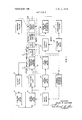
- FlG. l is a schematic block diagram circuit for one form of system according to the invention.
- FIG. 2 is a modified block diagram circuit for a warning system according to the invention.
- FIG. 3 is a circuit warning system according to the invention.
- FIG. 4 is a table showing the time delay changes which may be used in the circuit of FIG. 3 for a system according to the invention.
- the system according to the invention provides a small blue light placed substantially directly in the road line of vision of the operator on or above the instrument panel.
- This blue light is periodically illuminated in a regular sequence of timing, for example, every 4 minutes, while the vehicle is in motion and preferably above a predetermined speed.
- a floor switch is provided in the drivers compartment of the vehicle, and the operator has a predetermined period of time to press this switch to deactivate this system when the blue light is illuminated, for examplea 3 second time interval to react. If the operator presses the deactivate button, the system is deactivated and the timing sequence recommences until the light is again illuminated in its regular cycle.
- an alarm system an audio tone and sometimes a yellow light
- the operator then has a predetermined time to deact'ivate the alarm system by depressing the foot switch, and if diagram of one form of timing circuit of a the foot switch is not depressed a third alarm system is activated, including exterior emergency flashers and a loud audio horn are activated.
- the automobile engine is deactivated, either by breaking the ignition system or by a temporary disconnect of the accelerator to the engine.
- the foot switch may be depressed to deactivate the system and reset the timing sequence.
- a manual switch on the instrument panel is moved to reactivate the automobile engine and turn off the external flashers.
- FIG. 1 shows a general configuration of a system according to he invention.
- a warning system on and off switch 10 is connected to the ignition switch 12 so that the warning signal switch is turned on at the same time the ignition switch is turned on. This insures that the warning system is in effect at all times that the ignition switch is on.
- a further refinement may be to provide an override switch which will only permit the system to be activated above a particular speed, for example 40 miles per hour, whereby the operator in an urban area need not be bothered with the system since this is usually at slow speeds with traffic sufficient to keep the driver alert.
- a velocity switch 14 is introduced into the system and the system cannot be activated until the vehicle reaches the predetermined velocity.
- a 5 second time delay unit 16 prevents immediate energizing of the system on the activation of the velocity switch.
- a time delay unit 18 in the system provides a predetermined time delay in which an alert light is activated. A time delay of 10 to l20 seconds is indicated, however this may be a time delay unit providing any reasonable sequence which will test a driver's alertness, for example 2 to 5 minutes for open road driving may be satisfactory. The time delay may, also, be made to reduce the time interval as the vehicle speed is increased.
- the time delay unit 18 activates an alert light 20 at the end of the time delay, and a reset switch 22 (activated by the human operator of the vehicle on observing the alert light) deactivates the alert light and then resets time delay, starting the sequence of timing again.
- a 2 to 3 second time delay unit 24 activates a visual and audio alert system 26 and starts time delay system 30. Again the human operator on hearing or seeing the second warning system may reset the switch 22 deactivating the alert light, the audio visual warning, the time delay system 30 and starting the timing circuit 18 into another sequence.
- the audiovisual-warning circuit turns on a yellow light 28 (usually mounted on the instrument panel) and this remains on unless the operator resets the time delay circuits by reset switch 22. If the operator does not press the reset switch circuit 30 activates a latching circuit 32 and simultaneously a red light 34 and a I second time delay 40.
- the latching circuit activates a loud audio signal or horn (if desired) and external flashers in circuit 36.
- the driver has then 1 second to push a manual reset switch 38, and in the event that the driver does not, the 1 second time delay 40 activates a deceleration system 42, which may be any system which will deactivate the vehicle engine and actually stop the vehicle.
- a deceleration system 42 which may be any system which will deactivate the vehicle engine and actually stop the vehicle.
- Some of the deceleration systems would include those which disrupt the electrical system to theengine, for example a solenoid switch on the line from the coil to the distributor to disrupt the ignition system, a solenoid temporarily disconnecting the accelerator system, a combined system which disconnects the accelerator and automatically applies braking pressure to the braking system, etc.
- the stopping of the vehicle is of value if the driver has lost ability to drive for any reason, and the flashing emergency lights alerts other drivers of an emergency.
- a simplified circuit for only testing driver response is shown in the block diagram of FIG. 2, wherein a combined off and on switch and ignition switch 44 activates a time delay unit which activates and illuminates an alert light 48 and activates a second time delay unit 52. lf the human operator does not, within 2 to 3 seconds, deactivate the system by means of reset switch 50, the time delay unit 52 (which may be of the 2 to 3 second variety) activates an audio and visual warning circuit 54, which may be deactivated by means of the human operator actuating the reset switch 50.
- the audio and visual warning system may be made loud enough so that it is clearly heard even over the noises of a high-speed vehicle, and the visual system may be sufficient to alert a reasonably normal driver.
- timing circuit is shown in FIG. 12, where a hot line 60 is provided with an on and off switch 61, for example, similar to the one earlier described as connected with the ignition switch, to provide current to the circuit which is grounded at 62.
- the output 63 of the timing circuit actuates a warning light circuit and a second timing circuit, for example the alert light 20 of FIG. 1 leading to the audiovisual-warning circuit 26 and the timing circuit 24.
- a solid-state second timer 65 (any conventional timer) is connected across a diode 66, a semicontrolled rectifier (SCR) 73 and a resistance 77.
- the reset input passes through a resistor 68 to an SCR 69 and across resistor 71 to the ground 62.
- a lead from diode 66 goes to the base of the SCR 73 and the lead from the diode to the triode intercepts a lead from resistor 74.
- the input of the SCR 73 is also the base lead to SCR 76 both connected to resistor 77.
- the input for SCR 76 is from resistor 78.
- the output of triode 73 and the output of triode 79 join through resistor 80 onto the line 82.
- Resistor 83 and resistor 84 join to the base lead of SCR 79 and a resistor 86 is in the input line' to the SCR 79.
- the resistor 78 is a 1K resistance and the resistor 71 is a 10K resistance.
- the capacitor is a 0.1 FD and the two SCR's 73 and 78 are 2N5 l23s.
- the resistance 74 is a 20p. and the resistors 80 and 83 are 5k resistances.
- Input resistor 86 is a 1k resistor, and the resistor 84 on the input to the base of SCR 79 is a 7k.
- the SCR 76 is a 2N41l8 and resistor 78 is a 5g. resistance.
- the major purpose of the invention is to achieve a physical movement of the operator to insure that the operator is awake and alert.
- the foot switch for the reset may be placed in a position where it is generally out of the way but it is fairly readily reached by the left foot of the operator.
- the blue light in the vision of the operator, may be provided with a variable intensity, bright for daytime and dimmer for night driving. The intensity of the blue light may be controlled by means of a photoresistive cell so that it is automatically brightened or dimmed as the conditions change.
- the time units may be thermal time delay units and the change in time is achieved by changing the heater element. For example, 12N03T thermal time delay unit may be used in the system shown in FIG. 3.
- Thermal time delay units and solid state timers are conventional, and the circuit of the invention is simple and readily adapted to any conventional timer device.
- a magnetic reed proximity switch on the steering wheel or the steering column may be utilized where the movement of a few degrees in either direction resets the main sequence timer.
- a manual hand switch on the steering wheel may also be used.
- the operator is required to depress the reset switch each time the alert light is illuminated, and in the event the reset switch is not set the audiovisual warning is activated, which after 2 to 3 second delay activates the latching circuit and the external emergency system.
- This requires the use of a manual reset so that a driver who lets the warning system operate long enough for the horn and the external flashers to illuminate, must actuate the manual reset as well as the foot reset, which almost insures that the driver is alert and awake. With this system, the decelerate system cannot be reactivated without the driver resetting the manual reset and the foot reset.
- accelerator disconnect system may be made in such a manner that the accelerator cannot be reactivated until it is fully released by the operators foot and after the manual reset and the foot reset switches have been deactivated the acceleration system may then be reactivated. This requires another manual operation further helping to keep the driver alert.
- a system for periodically testing the alertness of a vehicle operator comprising a. first timer means;
- first alarm means periodically and automatically actuated by said first timer means
- c. means inclusive of a manually actuated switch for deactivating said first alarm means and restarting the timing sequence of said first timer means;
- second timer means actuated by said first timer means on actuation of said first alarm means and deactivated by said means inclusive of said manually actuated switch;
- second alarm means inclusive of an audio signal activated by said second timer means in the event said second timer means is not deactivated by said means inclusive of said manually actuated switch.
- a system for periodically testing the alertness of a vehicle operator according to claim 1 wherein said first timer means actuates said first alarm means in a range of from l0 seconds to 5 minutes.
- a system for periodically testing the alertness of a vehicle operator according to claim 1 wherein said first alarm means includes a light in the road line of vision of the vehicle operator.
- a system for periodically testing the alertness of a vehicle operator according to claim 1 wherein said second alarm means includes an audio alarm.
- a system for periodically testing the alertness of a vehicle operator according to claim 4 wherein said second alarm means includes an instrument panel mounted light and said audio alarm.
- a system for periodically testing the alertness of a vehicle operator according to claim 3 wherein said light is a blue light.
- a system for periodically testing the alertness of a vehicle operator comprising a. first timer means;
- first visual signal means periodically and automatically actuated by said first timer means
- c. means inclusive of a first manually actuated switch for deactivating said first visual signal means
- second time delay means actuated on actuating said first visual signal means by said first timer means
- second circuit means actuated by said second time delay means and arranged to be deactivated by said first manually actuated switch
- second signal means connected to said second circuit means including an audio signal actuated by said second time delay means
- third time delay means actuated on activation of said second signal means and deactivated by said first manually actuated switch
- third signal means actuated by said third circuit, including external emergency lights on said vehicle and means for deactivating the engine of said vehicle;
Abstract
A system for initiating conscious activity of a vehicle operator utilizes a visual alarm signal which is automatically and periodically actuated and which signal must be promptly manually deactivated by the operator to prevent actuation of an audio alarm signal which in turn must be promptly manually deactivated by the operator to prevent simultaneous actuation of external emergency flashing lights, an automobile horn and an engine deactivator which temporarily deactivate the vehicle engine for stopping the engine.
Description
United States Patent [72] Inven J h Conner 3,106,981 /1963 Chakiris 340/279 406 w. 12th St.,Loveland,Col0. 80537 3,1 6,508 6 1965 Lamont...,. 340 279 211 App]. No. 848,166 3,312,508 4/1967 Keller et al. 340 279 [22] Filed Aug. 7, 1969 Prim E h w C M ry xammer o n a we [45] Patented AssistantExaminer-J. Michael Bobbitt AttorneyRichard D. Law
[54] REACTION ACTUATOR FOR VEHICLE OPERATORS 10 Claims, 4 Drawing Figs.
...................................................... A ystem for initiating conscious activity of a 180/97, 340/52 R, 340/263 vehicle operator utilizes a visual alarm signal which is auto- Cl I G085 21/00 matically and periodically actuated and which signal must be of Search promptly manually deactivated the operator to prevent ac- 3 5 3 tuation of an audio alarm signal which in turn must be promptly manually deactivated by the operator to prevent [56] References cued simultaneous actuation of external emergency flashing lights,
UNITED STATES PATENTS an automobile horn and an engine deactivator which tem- 2,625,594 1/1953 Mathis 7 340/279 porarily deactivate the vehicle engine for stopping the engine.
/6 /4 5 53% TVELOCITY AWAKENED l DELAY SWTCH DRIVER /0 /2 I J ON OfFiWlIgH IGflTQI s wIT H L g L" 25 A34 37 y )38 l,{ SEC O SD E -ALERT l a 318 2 YEL. RED GREEN L lama TIME DELAY LIGHT I x l s lmz TLIsI-IT LIGHT LIGHT I RESET I fl l I 26 I I l 22 24 i 32 a;
2'3 RESET SECOND SE CO ND I LATCHING ail/ swIrc TIME 1 TIME I cIRcuIT EXTERNAL DELAY I DELAY FLASHERS l I RESET I 40 42 I HUMAN I I I SECOND OPERATOR J j ME DECELERATE RESPONSE V ELEMENT DELAY SYSTEM PATENTED 0m 5 l97| SHEET 1 UF 2 PATENTED um 5 l97i 3611.344
SHEET 2 OF 2 lO-l20 SECOND Z5351 IGNITION ON-OFF J 'EE UGHT I SWITCH swn'cu k l 50 52 5 2; I
SONALERT RESET SECOND l AUDIO a SWITCH TIME F VISUAL DELAY WARNING I I l I L Ga a 0N L l RESPONSE ELEMENT F IG. 2
OUTPUT 60\ON'\O;- 6/ f as RESETv INPUT C N FIG. 5
I Time Delay C Inc .5 Sec. O.lufd 0.5 i.OS0c. O.Iufd 0.25 210 Sec. O.lufd 4 INVENTOR 0.20 2.5 Sec. OJu'fd 0.|0 5.0 Sec. 01m COUPER 0.16 30.0 Sec. 0.1m
ATTORNEY 1 REACTION ACTUATOR FOR VEHICLE OPERATORS Statistics show that over 70 percent of all serious accidents on our nation's highways are one car accidents, and a great majority of these are caused by inattention of the driver caused by drowsiness, weariness, and actually falling asleep. These conditions impair the reaction time of the driver. In addition to the weariness and sleepiness of a driver, intoxication impairs the driver's ability to react accurately to the various situations which occur during driving. Sudden illnesses such as onslaught of a stroke, heart attacks and the like incapacitate the driver and usually before the driver can bring the vehicle to a complete stop.
According to the present invention there is provided a system protecting the operators and the vehicles from physical impairment. The system is arranged to periodically test the operator's alertness, reaction time and ability to act, permitting all normal maneuvers when the operator properly reacts, but stops the vehicle when the operator does not properly react The system includes a first periodic visual signal which requires a physical act to deactivate the signal each time the signal is activated. In the event the visual signal is not deactivated in a very short time an audio alarm is activated which requires the operator to physically react to deactivate the alarm and in the event the system is not deactivated emergency flashes are actuated and the engine of the vehicle is temporarily deactivated to prevent further operation of the vehicle.
Included among the objects and advantages of the present invention is a system for maintaining an automobile operator alert for operation thereof.
Another object of the invention is to provide a system of progressive warning signals for the purpose of maintaining a vehicle operator alert but which system is intended to be deactivated by physical movement of the operator on activation of each signal.
A further object of the invention is to provide a warning system for the operator of a motor vehicle which provides external warning for other vehicles and which stops the operation of the vehicle in the event the warning system is not deactivated.
A further object of the invention is to provide a system for automatically stopping a vehicle in the event the operator of the vehicle is unable to activate a warning system.
These and other objects and advantages of the invention may be readily ascertained by referring to the following description and appended illustrations in which:
FlG. l is a schematic block diagram circuit for one form of system according to the invention;
FIG. 2 is a modified block diagram circuit for a warning system according to the invention;
FIG. 3 is a circuit warning system according to the invention; and
FIG. 4 is a table showing the time delay changes which may be used in the circuit of FIG. 3 for a system according to the invention.
In general, the system according to the invention provides a small blue light placed substantially directly in the road line of vision of the operator on or above the instrument panel. This blue light is periodically illuminated in a regular sequence of timing, for example, every 4 minutes, while the vehicle is in motion and preferably above a predetermined speed. A floor switch is provided in the drivers compartment of the vehicle, and the operator has a predetermined period of time to press this switch to deactivate this system when the blue light is illuminated, for examplea 3 second time interval to react. If the operator presses the deactivate button, the system is deactivated and the timing sequence recommences until the light is again illuminated in its regular cycle. However, if the operator does not deactivate the system by the foot switch, an alarm system (an audio tone and sometimes a yellow light) on the instrument panel will be activated at the end of the three second period. The operator then has a predetermined time to deact'ivate the alarm system by depressing the foot switch, and if diagram of one form of timing circuit of a the foot switch is not depressed a third alarm system is activated, including exterior emergency flashers and a loud audio horn are activated. Simultaneously the automobile engine is deactivated, either by breaking the ignition system or by a temporary disconnect of the accelerator to the engine. At any time during the activation of the first two warning systems, the foot switch may be depressed to deactivate the system and reset the timing sequence. With the third, a manual switch on the instrument panel is moved to reactivate the automobile engine and turn off the external flashers.
The block diagram of FIG. 1 shows a general configuration of a system according to he invention. For effectiveness, a warning system on and off switch 10 is connected to the ignition switch 12 so that the warning signal switch is turned on at the same time the ignition switch is turned on. This insures that the warning system is in effect at all times that the ignition switch is on. A further refinement may be to provide an override switch which will only permit the system to be activated above a particular speed, for example 40 miles per hour, whereby the operator in an urban area need not be bothered with the system since this is usually at slow speeds with traffic sufficient to keep the driver alert. In this case a velocity switch 14 is introduced into the system and the system cannot be activated until the vehicle reaches the predetermined velocity. A 5 second time delay unit 16 prevents immediate energizing of the system on the activation of the velocity switch. A time delay unit 18 in the system provides a predetermined time delay in which an alert light is activated. A time delay of 10 to l20 seconds is indicated, however this may be a time delay unit providing any reasonable sequence which will test a driver's alertness, for example 2 to 5 minutes for open road driving may be satisfactory. The time delay may, also, be made to reduce the time interval as the vehicle speed is increased. The time delay unit 18 activates an alert light 20 at the end of the time delay, and a reset switch 22 (activated by the human operator of the vehicle on observing the alert light) deactivates the alert light and then resets time delay, starting the sequence of timing again. ln the event the operator does not press the reset switch, a 2 to 3 second time delay unit 24 activates a visual and audio alert system 26 and starts time delay system 30. Again the human operator on hearing or seeing the second warning system may reset the switch 22 deactivating the alert light, the audio visual warning, the time delay system 30 and starting the timing circuit 18 into another sequence. The audiovisual-warning circuit turns on a yellow light 28 (usually mounted on the instrument panel) and this remains on unless the operator resets the time delay circuits by reset switch 22. If the operator does not press the reset switch circuit 30 activates a latching circuit 32 and simultaneously a red light 34 and a I second time delay 40. The latching circuit activates a loud audio signal or horn (if desired) and external flashers in circuit 36. The driver has then 1 second to push a manual reset switch 38, and in the event that the driver does not, the 1 second time delay 40 activates a deceleration system 42, which may be any system which will deactivate the vehicle engine and actually stop the vehicle. Some of the deceleration systems would include those which disrupt the electrical system to theengine, for example a solenoid switch on the line from the coil to the distributor to disrupt the ignition system, a solenoid temporarily disconnecting the accelerator system, a combined system which disconnects the accelerator and automatically applies braking pressure to the braking system, etc. The stopping of the vehicle is of value if the driver has lost ability to drive for any reason, and the flashing emergency lights alerts other drivers of an emergency.
A simplified circuit for only testing driver response is shown in the block diagram of FIG. 2, wherein a combined off and on switch and ignition switch 44 activates a time delay unit which activates and illuminates an alert light 48 and activates a second time delay unit 52. lf the human operator does not, within 2 to 3 seconds, deactivate the system by means of reset switch 50, the time delay unit 52 (which may be of the 2 to 3 second variety) activates an audio and visual warning circuit 54, which may be deactivated by means of the human operator actuating the reset switch 50. In this simplified circuit there is no attempt to deactivate the vehicle itself, but it merely provides a means for keeping the operator alert and requires the operator to depress the reset switch in a predetermined period of time or the second warning systems will be alerted. The audio and visual warning system may be made loud enough so that it is clearly heard even over the noises of a high-speed vehicle, and the visual system may be sufficient to alert a reasonably normal driver.
One form of timing circuit is shown in FIG. 12, where a hot line 60 is provided with an on and off switch 61, for example, similar to the one earlier described as connected with the ignition switch, to provide current to the circuit which is grounded at 62. The output 63 of the timing circuit actuates a warning light circuit and a second timing circuit, for example the alert light 20 of FIG. 1 leading to the audiovisual-warning circuit 26 and the timing circuit 24. A solid-state second timer 65 (any conventional timer) is connected across a diode 66, a semicontrolled rectifier (SCR) 73 and a resistance 77. The reset input passes through a resistor 68 to an SCR 69 and across resistor 71 to the ground 62. A lead from diode 66 goes to the base of the SCR 73 and the lead from the diode to the triode intercepts a lead from resistor 74. The input of the SCR 73 is also the base lead to SCR 76 both connected to resistor 77. The input for SCR 76 is from resistor 78. The output of triode 73 and the output of triode 79 join through resistor 80 onto the line 82. Resistor 83 and resistor 84 join to the base lead of SCR 79 and a resistor 86 is in the input line' to the SCR 79. With a 12 volt circuit, the resistor 78 is a 1K resistance and the resistor 71 is a 10K resistance. The capacitor is a 0.1 FD and the two SCR's 73 and 78 are 2N5 l23s. The resistance 74 is a 20p. and the resistors 80 and 83 are 5k resistances. Input resistor 86 is a 1k resistor, and the resistor 84 on the input to the base of SCR 79 is a 7k. The SCR 76 is a 2N41l8 and resistor 78 is a 5g. resistance. With this circuit the timing unit 65 may be changed as shown in the chart of FIG. 4, thus by changing the unit I to that shown in the chart various time delays for the output may be achieved.
The major purpose of the invention is to achieve a physical movement of the operator to insure that the operator is awake and alert. The foot switch for the reset may be placed in a position where it is generally out of the way but it is fairly readily reached by the left foot of the operator. The blue light, in the vision of the operator, may be provided with a variable intensity, bright for daytime and dimmer for night driving. The intensity of the blue light may be controlled by means of a photoresistive cell so that it is automatically brightened or dimmed as the conditions change. The time units may be thermal time delay units and the change in time is achieved by changing the heater element. For example, 12N03T thermal time delay unit may be used in the system shown in FIG. 3. Thermal time delay units and solid state timers are conventional, and the circuit of the invention is simple and readily adapted to any conventional timer device. In place of a foot reset switch, a magnetic reed proximity switch on the steering wheel or the steering column may be utilized where the movement of a few degrees in either direction resets the main sequence timer. A manual hand switch on the steering wheel may also be used.
In the case of the circuit of FIG. 1, the operator is required to depress the reset switch each time the alert light is illuminated, and in the event the reset switch is not set the audiovisual warning is activated, which after 2 to 3 second delay activates the latching circuit and the external emergency system. This requires the use of a manual reset so that a driver who lets the warning system operate long enough for the horn and the external flashers to illuminate, must actuate the manual reset as well as the foot reset, which almost insures that the driver is alert and awake. With this system, the decelerate system cannot be reactivated without the driver resetting the manual reset and the foot reset. One advantage of the accelerator disconnect system, it may be made in such a manner that the accelerator cannot be reactivated until it is fully released by the operators foot and after the manual reset and the foot reset switches have been deactivated the acceleration system may then be reactivated. This requires another manual operation further helping to keep the driver alert.
While the invention has been illustrated by reference to particular devices, there is no intent to limit the spirit or scope of the invention to the precise details so set forth except as defined in the present claims.
I claim:
1. A system for periodically testing the alertness of a vehicle operator comprising a. first timer means;
b. first alarm means periodically and automatically actuated by said first timer means;
c. means inclusive of a manually actuated switch for deactivating said first alarm means and restarting the timing sequence of said first timer means;
d. second timer means actuated by said first timer means on actuation of said first alarm means and deactivated by said means inclusive of said manually actuated switch; and
e. second alarm means inclusive of an audio signal activated by said second timer means in the event said second timer means is not deactivated by said means inclusive of said manually actuated switch.
2. A system for periodically testing the alertness of a vehicle operator according to claim 1 wherein said first timer means actuates said first alarm means in a range of from l0 seconds to 5 minutes.
3. A system for periodically testing the alertness of a vehicle operator according to claim 1 wherein said first alarm means includes a light in the road line of vision of the vehicle operator.
4. A system for periodically testing the alertness of a vehicle operator according to claim 1 wherein said second alarm means includes an audio alarm.
5. A system for periodically testing the alertness of a vehicle operator according to claim 4 wherein said second alarm means includes an instrument panel mounted light and said audio alarm.
6. A system for periodically testing the alertness of a vehicle operator according to claim 3 wherein said light is a blue light.
7. A system for periodically testing the alertness of a vehicle operator comprising a. first timer means;
b. first visual signal means periodically and automatically actuated by said first timer means;
c. means inclusive of a first manually actuated switch for deactivating said first visual signal means;
d. second time delay means actuated on actuating said first visual signal means by said first timer means;
e. second circuit means actuated by said second time delay means and arranged to be deactivated by said first manually actuated switch;
f. second signal means connected to said second circuit means including an audio signal actuated by said second time delay means;
g. third time delay means actuated on activation of said second signal means and deactivated by said first manually actuated switch;
h. third circuit means actuated by said third time delay means;
. third signal means actuated by said third circuit, including external emergency lights on said vehicle and means for deactivating the engine of said vehicle;
j. and means inclusive of second manual switch means for deactivating said third circuit thereby deactivating said emergency lights and reactivating the engine of said vehicle.
8. A system for periodically testing the alertness of a vehicle operator according to claim 7 wherein said first timer means 10. A system for periodically testing the alertness of a vehicle operator according to claim 8 wherein said second and third time delay means provide a time interval of from 2 to 3 seconds.
Claims (10)
1. A system for periodically testing the alertness of a vehicle operator comprising a. first timer means; b. first alarm means periodically and automatically actuated by said first timer means; c. means inclusive of a manually actuated switch for deactivating said first alarm means and restarting the timing sequence of said first timer means; d. second timer means actuated by said first timer means on actuation of said first alarm means and deactivated by said means inclusive of said manually actuated switch; and e. second alarm means inclusive of an audio signal activated by said second timer means in the event said second timer means is not deactivated by said means inclusive of said manually actuated switch.
2. A system for periodically testing the alertness of a vehicle operator according to claim 1 wherein said first timer means actuates said first alarm means in a range of from 10 seconds to 5 minutes.
3. A system for periodically testing the alertness of a vehicle operator according to claim 1 wherein said first alarm means includes a light in the road line of vision of the vehicle operator.
4. A system for periodically testing the alErtness of a vehicle operator according to claim 1 wherein said second alarm means includes an audio alarm.
5. A system for periodically testing the alertness of a vehicle operator according to claim 4 wherein said second alarm means includes an instrument panel mounted light and said audio alarm.
6. A system for periodically testing the alertness of a vehicle operator according to claim 3 wherein said light is a blue light.
7. A system for periodically testing the alertness of a vehicle operator comprising a. first timer means; b. first visual signal means periodically and automatically actuated by said first timer means; c. means inclusive of a first manually actuated switch for deactivating said first visual signal means; d. second time delay means actuated on actuating said first visual signal means by said first timer means; e. second circuit means actuated by said second time delay means and arranged to be deactivated by said first manually actuated switch; f. second signal means connected to said second circuit means including an audio signal actuated by said second time delay means; g. third time delay means actuated on activation of said second signal means and deactivated by said first manually actuated switch; h. third circuit means actuated by said third time delay means; i. third signal means actuated by said third circuit, including external emergency lights on said vehicle and means for deactivating the engine of said vehicle; j. and means inclusive of second manual switch means for deactivating said third circuit thereby deactivating said emergency lights and reactivating the engine of said vehicle.
8. A system for periodically testing the alertness of a vehicle operator according to claim 7 wherein said first timer means provides a relatively long time interval for the periodical activation of said first signal means, and second and third time delay means provide a relatively short time interval.
9. A system for periodically testing the alertness of a vehicle operator according to claim 7 wherein said third circuit means includes a red light signal means.
10. A system for periodically testing the alertness of a vehicle operator according to claim 8 wherein said second and third time delay means provide a time interval of from 2 to 3 seconds.
Applications Claiming Priority (1)
| Application Number | Priority Date | Filing Date | Title |
|---|---|---|---|
| US84816669A | 1969-08-07 | 1969-08-07 |
Publications (1)
| Publication Number | Publication Date |
|---|---|
| US3611344A true US3611344A (en) | 1971-10-05 |
Family
ID=25302529
Family Applications (1)
| Application Number | Title | Priority Date | Filing Date |
|---|---|---|---|
| US848166A Expired - Lifetime US3611344A (en) | 1969-08-07 | 1969-08-07 | Reaction actuator for vehicle operators |
Country Status (1)
| Country | Link |
|---|---|
| US (1) | US3611344A (en) |
Cited By (33)
| Publication number | Priority date | Publication date | Assignee | Title |
|---|---|---|---|---|
| US3771122A (en) * | 1972-08-11 | 1973-11-06 | Gen Motors Corp | Motor vehicle automatic hazard warning system |
| US3788357A (en) * | 1972-03-31 | 1974-01-29 | Casco Products Corp | Fluidic driver alertness system |
| US3794968A (en) * | 1972-09-11 | 1974-02-26 | Raytheon Co | Analyzer for comparing the response of an organism to a reference pattern |
| US3855574A (en) * | 1973-06-25 | 1974-12-17 | Vox Ind Inc | Voice operated alarm system |
| US3922665A (en) * | 1974-10-04 | 1975-11-25 | Whittaker Corp | Apparatus and method for maintaining operator alertness |
| US4005398A (en) * | 1974-04-16 | 1977-01-25 | Nissan Motor Co., Ltd. | Method of determining the driver's sufficient alertness to drive a motor vehicle safely |
| US4234051A (en) * | 1978-07-26 | 1980-11-18 | Morris Jr Solon S | Driver alertness device |
| EP0030021A2 (en) * | 1979-11-29 | 1981-06-10 | ELEKTROMOBIL Elektro és Jármüipari Szövetkezet | Method and apparatus for checking the fitness of the driver of a road vehicle |
| US4348663A (en) * | 1979-08-29 | 1982-09-07 | Nissan Motor Company, Limited | Safety assurance system for road vehicles |
| US4436176A (en) | 1981-12-14 | 1984-03-13 | Cota Albert O | Delayed vehicle starter |
| US4524243A (en) * | 1983-07-07 | 1985-06-18 | Lifeline Systems, Inc. | Personal alarm system |
| WO1986001468A1 (en) * | 1984-08-23 | 1986-03-13 | Kim Leidersdorff Johansen | An alarm device for automobiles and similar vehicles |
| GB2202665A (en) * | 1987-03-04 | 1988-09-28 | Adrian Charles Elsey | Alarm systems |
| US4879542A (en) * | 1988-08-24 | 1989-11-07 | Elsey Adrian C | Alarm systems |
| US5012226A (en) * | 1990-02-23 | 1991-04-30 | Love Samuel D | Safety alertness monitoring system |
| EP0443826A2 (en) * | 1990-02-23 | 1991-08-28 | Samuel D. Love | Safety alertness monitoring system and geographical game usable therewith |
| US5341129A (en) * | 1991-11-07 | 1994-08-23 | Rpm Detection, Inc. | Zero-motion detection proximity switch |
| US5392030A (en) * | 1993-03-29 | 1995-02-21 | Adams; George W. | Locomotive personal alert system |
| US5402108A (en) * | 1993-03-08 | 1995-03-28 | Just Right, Inc. | Driver alerting system |
| EP0680728A1 (en) * | 1994-05-04 | 1995-11-08 | Alisea - Assistenza Logistica e Ingegneria per i Sistemi Elettronici e d'Automazione Srl | System for the automatic monitoring of the level of the attention of a human operator |
| AU677598B2 (en) * | 1992-09-28 | 1997-05-01 | Giacomo Biviano | Warning system |
| US5684455A (en) * | 1996-01-29 | 1997-11-04 | Williams; Pete Bernard | Driver alert apparatus |
| WO2001060254A1 (en) * | 2000-02-15 | 2001-08-23 | Active Attention Ab | Method and means for monitoring driver alertness |
| US20040054452A1 (en) * | 2000-08-01 | 2004-03-18 | Mats Bjorkman | Methods and means for monitoring driver alertness and display means for displaying information related thereto |
| GB2417101A (en) * | 2004-08-10 | 2006-02-15 | Christopher Owen Hackling | Device for maintaining awareness of a driver |
| US20070174099A1 (en) * | 2006-01-26 | 2007-07-26 | Ostroscki Silvio Artur Koin | Personnel performance monitoring system and method |
| US20080059990A1 (en) * | 2006-09-01 | 2008-03-06 | Marr John N | Behavioral attention control apparatus |
| US20090058624A1 (en) * | 2007-08-28 | 2009-03-05 | Quantum Engineering, Inc. | Cognitive alerter |
| US20090261979A1 (en) * | 1992-05-05 | 2009-10-22 | Breed David S | Driver Fatigue Monitoring System and Method |
| US7777619B2 (en) | 2007-04-11 | 2010-08-17 | Ford Global Technologies, Llc | System and method for implementing active safety counter measures for an impaired driver |
| US20140097957A1 (en) * | 1995-06-07 | 2014-04-10 | American Vehicular Sciences Llc | Driver fatigue monitoring system and method |
| US20140231166A1 (en) * | 2011-08-11 | 2014-08-21 | Ford Global Technologies, Llc | System and method for establishing acoustic metrics to detect driver impairment |
| US20230005356A1 (en) * | 2021-06-30 | 2023-01-05 | Caterpillar Inc. | Systems and methods to retrigger detection based proximity alarm systems |
Citations (4)
| Publication number | Priority date | Publication date | Assignee | Title |
|---|---|---|---|---|
| US2625594A (en) * | 1949-03-11 | 1953-01-13 | John A Mathis | Device for inhibiting sleep |
| US3106981A (en) * | 1961-04-03 | 1963-10-15 | Metro Mac Inc | Electronic driving assurance system |
| US3186508A (en) * | 1963-03-06 | 1965-06-01 | Lewis H Lamont | Emergency control for a vehicle |
| US3312508A (en) * | 1964-12-30 | 1967-04-04 | William M Keller | Electronic alertness control |
-
1969
- 1969-08-07 US US848166A patent/US3611344A/en not_active Expired - Lifetime
Patent Citations (4)
| Publication number | Priority date | Publication date | Assignee | Title |
|---|---|---|---|---|
| US2625594A (en) * | 1949-03-11 | 1953-01-13 | John A Mathis | Device for inhibiting sleep |
| US3106981A (en) * | 1961-04-03 | 1963-10-15 | Metro Mac Inc | Electronic driving assurance system |
| US3186508A (en) * | 1963-03-06 | 1965-06-01 | Lewis H Lamont | Emergency control for a vehicle |
| US3312508A (en) * | 1964-12-30 | 1967-04-04 | William M Keller | Electronic alertness control |
Cited By (43)
| Publication number | Priority date | Publication date | Assignee | Title |
|---|---|---|---|---|
| US3788357A (en) * | 1972-03-31 | 1974-01-29 | Casco Products Corp | Fluidic driver alertness system |
| US3771122A (en) * | 1972-08-11 | 1973-11-06 | Gen Motors Corp | Motor vehicle automatic hazard warning system |
| US3794968A (en) * | 1972-09-11 | 1974-02-26 | Raytheon Co | Analyzer for comparing the response of an organism to a reference pattern |
| US3855574A (en) * | 1973-06-25 | 1974-12-17 | Vox Ind Inc | Voice operated alarm system |
| US4005398A (en) * | 1974-04-16 | 1977-01-25 | Nissan Motor Co., Ltd. | Method of determining the driver's sufficient alertness to drive a motor vehicle safely |
| US3922665A (en) * | 1974-10-04 | 1975-11-25 | Whittaker Corp | Apparatus and method for maintaining operator alertness |
| US4234051A (en) * | 1978-07-26 | 1980-11-18 | Morris Jr Solon S | Driver alertness device |
| US4348663A (en) * | 1979-08-29 | 1982-09-07 | Nissan Motor Company, Limited | Safety assurance system for road vehicles |
| EP0030021A3 (en) * | 1979-11-29 | 1981-10-21 | Elektromobil Elektro Es Jarmuipari Szovetkezet | Method and device for checking the vigilance level of a vehicle driver |
| EP0030021A2 (en) * | 1979-11-29 | 1981-06-10 | ELEKTROMOBIL Elektro és Jármüipari Szövetkezet | Method and apparatus for checking the fitness of the driver of a road vehicle |
| US4359725A (en) * | 1979-11-29 | 1982-11-16 | Elektromobil Elektroes Jarmuipari Szovetkezet | Method and apparatus for monitoring the alertness of the driver of a vehicle |
| US4436176A (en) | 1981-12-14 | 1984-03-13 | Cota Albert O | Delayed vehicle starter |
| US4524243A (en) * | 1983-07-07 | 1985-06-18 | Lifeline Systems, Inc. | Personal alarm system |
| WO1986001468A1 (en) * | 1984-08-23 | 1986-03-13 | Kim Leidersdorff Johansen | An alarm device for automobiles and similar vehicles |
| US4679648A (en) * | 1984-08-23 | 1987-07-14 | Johansen Kim L | Alarm device for automobiles and similar vehicles |
| GB2202665A (en) * | 1987-03-04 | 1988-09-28 | Adrian Charles Elsey | Alarm systems |
| GB2202665B (en) * | 1987-03-04 | 1991-02-20 | Adrian Charles Elsey | Alarm systems |
| US4879542A (en) * | 1988-08-24 | 1989-11-07 | Elsey Adrian C | Alarm systems |
| EP0443826A3 (en) * | 1990-02-23 | 1991-10-23 | Samuel D. Love | Safety alertness monitoring system and geographical game usable therewith |
| US5012226A (en) * | 1990-02-23 | 1991-04-30 | Love Samuel D | Safety alertness monitoring system |
| EP0443826A2 (en) * | 1990-02-23 | 1991-08-28 | Samuel D. Love | Safety alertness monitoring system and geographical game usable therewith |
| US5341129A (en) * | 1991-11-07 | 1994-08-23 | Rpm Detection, Inc. | Zero-motion detection proximity switch |
| US20090261979A1 (en) * | 1992-05-05 | 2009-10-22 | Breed David S | Driver Fatigue Monitoring System and Method |
| US8604932B2 (en) * | 1992-05-05 | 2013-12-10 | American Vehicular Sciences, LLC | Driver fatigue monitoring system and method |
| AU677598B2 (en) * | 1992-09-28 | 1997-05-01 | Giacomo Biviano | Warning system |
| US5402108A (en) * | 1993-03-08 | 1995-03-28 | Just Right, Inc. | Driver alerting system |
| US5392030A (en) * | 1993-03-29 | 1995-02-21 | Adams; George W. | Locomotive personal alert system |
| EP0680728A1 (en) * | 1994-05-04 | 1995-11-08 | Alisea - Assistenza Logistica e Ingegneria per i Sistemi Elettronici e d'Automazione Srl | System for the automatic monitoring of the level of the attention of a human operator |
| US20140097957A1 (en) * | 1995-06-07 | 2014-04-10 | American Vehicular Sciences Llc | Driver fatigue monitoring system and method |
| US9129505B2 (en) * | 1995-06-07 | 2015-09-08 | American Vehicular Sciences Llc | Driver fatigue monitoring system and method |
| US5684455A (en) * | 1996-01-29 | 1997-11-04 | Williams; Pete Bernard | Driver alert apparatus |
| US20030011481A1 (en) * | 2000-02-15 | 2003-01-16 | Bjoerkman Mats | Method and means for monitoring driver alertness |
| WO2001060254A1 (en) * | 2000-02-15 | 2001-08-23 | Active Attention Ab | Method and means for monitoring driver alertness |
| US20040054452A1 (en) * | 2000-08-01 | 2004-03-18 | Mats Bjorkman | Methods and means for monitoring driver alertness and display means for displaying information related thereto |
| GB2417101A (en) * | 2004-08-10 | 2006-02-15 | Christopher Owen Hackling | Device for maintaining awareness of a driver |
| US20070174099A1 (en) * | 2006-01-26 | 2007-07-26 | Ostroscki Silvio Artur Koin | Personnel performance monitoring system and method |
| US20080059990A1 (en) * | 2006-09-01 | 2008-03-06 | Marr John N | Behavioral attention control apparatus |
| US7777619B2 (en) | 2007-04-11 | 2010-08-17 | Ford Global Technologies, Llc | System and method for implementing active safety counter measures for an impaired driver |
| US20090058624A1 (en) * | 2007-08-28 | 2009-03-05 | Quantum Engineering, Inc. | Cognitive alerter |
| US20140231166A1 (en) * | 2011-08-11 | 2014-08-21 | Ford Global Technologies, Llc | System and method for establishing acoustic metrics to detect driver impairment |
| US9963033B2 (en) * | 2011-08-11 | 2018-05-08 | Ford Global Technologies, Llc | System and method for establishing acoustic metrics to detect driver impairment |
| US20230005356A1 (en) * | 2021-06-30 | 2023-01-05 | Caterpillar Inc. | Systems and methods to retrigger detection based proximity alarm systems |
| US11574534B2 (en) * | 2021-06-30 | 2023-02-07 | Caterpillar Inc. | Systems and methods to retrigger detection based proximity alarm systems |
Similar Documents
| Publication | Publication Date | Title |
|---|---|---|
| US3611344A (en) | Reaction actuator for vehicle operators | |
| US5243323A (en) | School bus alarm system | |
| US5404130A (en) | Sudden-stop brake-light warning system | |
| US5012226A (en) | Safety alertness monitoring system | |
| US6946965B2 (en) | Driver fatigue detector with automatic deactivation | |
| US4346365A (en) | Stopped vehicle warning device | |
| US20130321143A1 (en) | Modulated intensity flasher for vehicle brake light with accelerometer detection of hard-braking movement and backing-out indicator | |
| US2625594A (en) | Device for inhibiting sleep | |
| US3375496A (en) | Deceleration indicator for motor vehicles | |
| US6166631A (en) | Method and apparatus for alerting a vehicle driver of an operating condition | |
| US3708782A (en) | Abrupt brake application indicator for a motor vehicle | |
| US6023227A (en) | Alerting system and method for maintaining the awareness of a driver | |
| US3396811A (en) | Remote control for automobiles | |
| US3925759A (en) | Auxiliary emergency warning light system | |
| DE4200642A1 (en) | Vehicular driver vigilance alarm coupled to steering wheel - incorporates two timed circuits for successive alerting of inattentive driver and of others at risk. | |
| US5621252A (en) | Apparatus for preventing unauthorized use of machinery | |
| US3496535A (en) | Vehicle speed control and signalling system | |
| US3821701A (en) | Automobile deceleration indicating device | |
| US6693526B1 (en) | Brake light system for a vehicle | |
| US3213417A (en) | Vehicle acceleration signalling systems | |
| US3411134A (en) | Control device for vehicle brake light | |
| US3051258A (en) | Vehicle operator alarm | |
| US3439325A (en) | Signalling means for indicating change in speed of an automotive vehicle | |
| US4587512A (en) | Turn signal alarm | |
| US2911635A (en) | Signal equipment for motor vehicles |