US3673906A - Automatic border panel measuring and cutting machine - Google Patents
Automatic border panel measuring and cutting machine Download PDFInfo
- Publication number
- US3673906A US3673906A US71086A US3673906DA US3673906A US 3673906 A US3673906 A US 3673906A US 71086 A US71086 A US 71086A US 3673906D A US3673906D A US 3673906DA US 3673906 A US3673906 A US 3673906A
- Authority
- US
- United States
- Prior art keywords
- knife
- cutting
- panel
- machine
- measuring
- Prior art date
- Legal status (The legal status is an assumption and is not a legal conclusion. Google has not performed a legal analysis and makes no representation as to the accuracy of the status listed.)
- Expired - Lifetime
Links
Images


Classifications
-
- B—PERFORMING OPERATIONS; TRANSPORTING
- B68—SADDLERY; UPHOLSTERY
- B68G—METHODS, EQUIPMENT, OR MACHINES FOR USE IN UPHOLSTERING; UPHOLSTERY NOT OTHERWISE PROVIDED FOR
- B68G7/00—Making upholstery
-
- Y—GENERAL TAGGING OF NEW TECHNOLOGICAL DEVELOPMENTS; GENERAL TAGGING OF CROSS-SECTIONAL TECHNOLOGIES SPANNING OVER SEVERAL SECTIONS OF THE IPC; TECHNICAL SUBJECTS COVERED BY FORMER USPC CROSS-REFERENCE ART COLLECTIONS [XRACs] AND DIGESTS
- Y10—TECHNICAL SUBJECTS COVERED BY FORMER USPC
- Y10T—TECHNICAL SUBJECTS COVERED BY FORMER US CLASSIFICATION
- Y10T83/00—Cutting
- Y10T83/444—Tool engages work during dwell of intermittent workfeed
- Y10T83/4455—Operation initiated by work-driven detector means to measure work length
-
- Y—GENERAL TAGGING OF NEW TECHNOLOGICAL DEVELOPMENTS; GENERAL TAGGING OF CROSS-SECTIONAL TECHNOLOGIES SPANNING OVER SEVERAL SECTIONS OF THE IPC; TECHNICAL SUBJECTS COVERED BY FORMER USPC CROSS-REFERENCE ART COLLECTIONS [XRACs] AND DIGESTS
- Y10—TECHNICAL SUBJECTS COVERED BY FORMER USPC
- Y10T—TECHNICAL SUBJECTS COVERED BY FORMER US CLASSIFICATION
- Y10T83/00—Cutting
- Y10T83/444—Tool engages work during dwell of intermittent workfeed
- Y10T83/4458—Work-sensing means to control work-moving or work-stopping means
-
- Y—GENERAL TAGGING OF NEW TECHNOLOGICAL DEVELOPMENTS; GENERAL TAGGING OF CROSS-SECTIONAL TECHNOLOGIES SPANNING OVER SEVERAL SECTIONS OF THE IPC; TECHNICAL SUBJECTS COVERED BY FORMER USPC CROSS-REFERENCE ART COLLECTIONS [XRACs] AND DIGESTS
- Y10—TECHNICAL SUBJECTS COVERED BY FORMER USPC
- Y10T—TECHNICAL SUBJECTS COVERED BY FORMER US CLASSIFICATION
- Y10T83/00—Cutting
- Y10T83/869—Means to drive or to guide tool
- Y10T83/8776—Constantly urged tool or tool support [e.g., spring biased]
- Y10T83/8779—Oscillating tool urged axially
- Y10T83/8781—And urged about pivotal axis
Definitions
- ABSTRACT An automatic border panel measuring and cutting machine wherein motorized pinch rollers feed a measured length of a mattress border panel and then stop while a pivotally mounted knife swings from a ready position through a cutting zone, in which it cuts off that measured length, and then returns to its ready position to start the next feed and cut cycle.
- the knife which is pivotally mounted at one end, has its opposite or free end not only connected to an air cylinder piston, which moves the knife back and forth for cutting and return purposes, but also engaged, during the cutting movement, by a yieldable guide means which directs the cutting edge of the knife into progressively tighter yieldable cutting (and knife-sharpening) engagement with a fixed cooperative cutting edge on the machine.
- the air cylinder is mounted for right and left and for front and rear pivotal movements to accommodate the corresponding movements of the blade.
- FIG'8 DAVID R. CASH 4 W ATTORNEY BACKGROUND OF THE INVENTION l Field of Thelnvention In manufacturing mattresses, it is customary to enclose the mattress within an outer cover composed of bottom and top face panels sewn to the bottom and top edges of a border panel encircling the periphery of the mattress. It is also custo mary to manufacture an elongate supply strip of border panel material and then cut it into border panels of a length required by the periphery of a given size mattress.
- the present invention relates to the art of measuring and cutting the supply material into border panels of a desired length.
- my automatic border panel measuring and cutting machine which comprises: A. a motorized panel-feed means operative, when actuated, to feed the border panel material forwardly over a fixed cutting edge of the machine; B. a knife blade pivotally mounted to swing back and forth across said cutting edge between ready and spent positions; C. power means operative, when actuated one way and the other, to swing said knife from its ready position to its spent position and vice versa; D. control means for instituting and controlling the operations of the machine including 1.
- a measuring meter settable to measure a selected length of border panel material and operative, upon measuring that length, to stop the motorized feed means and contemporaneously actuate the power means one way and thereby swing the knife blade to cut the measured material
- blade actuated switch means operative, at the end of the cutting operation, to actuate the power means in the opposite way and thereby return the knife blade to its ready position and contemporaneously reset said measuring meter and thereby condition it for the next cutting operation
- blade actuated switch means operative, in response to the return of the blade, to actuate the motorized feed means; and E. yieldable guide means engaging the knife during its cutting movement and, through such engagement, directing the cutting edge of the knife into progressively tighter yieldable cutting engagement with a panel on said fixed cutting edge.
- FIG. 1 is a schematic view showing a border panel manufacturing apparatus feeding an elongate supply of border panel material into a border panel measuring and cutting machine, which is constructed in accordance with the present invention
- FIG. 2 is a perspective view looking at the rear and left" side face of my measuring and cutting machine
- FIG. 3 is an elevational view of the upper half of the rear face of the machine shown in FIG. 2, this view omitting part of the mechanism for raising the upper feed roll;
- FIG. 4 is a side elevational view of the upper part of the mechanism for raising the upper feed roll
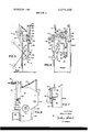
- FIG. 5 is a side elevational view of the left" side of my machine
- FIG. 6 is an elevational view of the front face of my machine with the knife in its uppermost position
- FIG. 7 is a fragmentary sectional view taken along line 7-7 of FIG. 6.
- FIG. 8 is an elevational view of the upper half of the right" side of the machine.
- FIG. 9 is a somewhat schematic view showing the electrical circuit system for and associated portions of the machine.
- FIG. 10 is a schematic view illustrating a portion of FIG. 9 during the cutting operation.
- FIG. 1 shows a table 1 supporting a roll of wadding 2 and a roll of decorative mattress ticking material 3. These materials are fed forwardly through a border panel manufacturing machine 4 and sewn together by its sewing machine 5 to form a product panel 6, which passes downwardly around the heavy end of a sensor 7 and upwardly into a border panel measuring and cutting machine 8.
- the latter which is constructed in accordance with the present invention, is hereinafter called the cutting machine.
- the heavy end of the sensor 7 rides on that portion of the panel 6, which extends between the manufacturing machine 4 and the cutting machine 8.
- the sensor 7 thus rises and falls as the length of the panel 6 between those machines decreases and increases.
- the sensor 7 rises to a predetermined elevation, it will operate a deficient supply" switch 9 to shut down the cutting machine.
- the manufacturing machine 4 will continue to operate; hence, the length of the panel 6 between the two machines will increase and thereby lower the sensor 7.
- the sensor When the sensorreaches its lowermost position, it will close a slack" switch 10, which enables the cutting machine 8 to start operating again in its normal fashion.
- the cutting machine 8 illustrated basically includes five elements comprising: A. motorized panel-feed means; B. a knife blade; C. power means for operating the knife; D. control means; and E. yieldable guide means. These elements are mounted on an upright channel-shaped casing 12 which opens rearwardly so that the wide bight or web of the channel" constitutes the front wall 13 of the casing while the rearwardly extending legs of the channel, as seen from the front of the machine, constitute the casings right and left side walls 14 and 15, respectively.
- the upper end of the channel is open.
- the upper end portion of the casings right side wall 14 carries a rigidly-mounted, rearwardly extending extension plate 16.
- the panel-feed means comprises an electric drive motor 18 located within the central portion of the casing 12 and mounted on the back face of its front wall 13.
- the drive motor 18 is connected by chain 19 to the lower roll 20 of a pair of pinch rollers 20, 21, the upper roll 21 of which is driven by the lower roll through identical lower and upper trains of elements.
- the lower train of elements comprises: one gear on the shaft of the lower pinch roll 20; another gear 22 spaced rearwardly therefrom and located adjacent the right side wall extension plate 16 on which it is rotationally mounted; and a chain 23 interconnecting said one gear on the lower pinch roll 20 with the shaft of said other gear 22.
- the upper train comprises: a floating gear 24 resting on and meshing with gear 22 of the lower train; and a chain 25 connecting the shaft of floating gear 24 with a corresponding gear on the shaft of the upper pinch roll 21.
- the lower and upper trains of elements 22-25 are used to facilitate the use of foot-operated means for raising and lowering the upper roll 21 pivotally about the axis of the floating gear 24 for panel threading purposes.
- the foot-operated means for raising and lowering the upper pinch roll 21 comprise: a horizontal rearwardly open U-shaped frame 26 having a bight closely overlying the upper roll 21 and a pair of horizontal rearwardly extending legs, each leg having a front lug (which depends downwardly to carry the corresponding end of the upper pinch roll 21), a rear lug 27 (which depends downwardly to the shaft of the floating gear 24 and is connected thereto to pivot about the axis thereof) and an upturned rear end; a vertical upwardly open U-shaped frame 28 having the upper ends of its legs pivotally connected to the rear upturned ends of the horizontal U-shaped frame 26 and its bight connected, through vertical link 29, to the mid-portion of a horizontal lever 30, one end of which is pivotally mounted near the bottom of an intumed marginal flange on the left
- the knife 33 is pivotally mounted on the casing for movement from an upwardly inclined ready" position downwardly to a horizontally extending spent" position. In the latter stages of this movement, the knife passes downwardly not only across a panel outlet slot 34 in the front wall of the casing, but also across a horizontally extending knife edge 35 fixedly mounted on the front face of the front wall 13 of the casing immediately adjacent the lower edge of the slot 34. More particularly, the knife 33 is pivotally mounted on a thick bar 36 which is fixedly secured to the casing to extend laterally outward from its left side wall 15 at a level slightly below the level of the fixed knife edge 35 on the casing. In this way, the knife reaches its spent position immediately after completing its movement through the cutting zone.
- the knife swinging power means which is operative when actuated one way and the other to swing the knife from its upper ready position to its lower spent position and vice versa, comprises: a power actuated fluid cylinder 38, preferably an air cylinder, having a piston rod 39 which projects from one end of the cylinder 38 and which has its outer projecting end pivotally connected at 40 to the free end portion of the knife 33; means mounting the cylinder on the front wall of the casing in a more or less upright position such that its piston rod 39 moves the knife up and down between its ready and spent positions; and double acting (solenoid and spring) air valve unit 41 mounted on the front wall of the casing, and arranged to be actuated in one direction by a solenoid 42 and in the opposite direction by a spring 43.
- the solenoid and spring 42, 43 are shown only in FIG. 9.
- the air valve of unit 41 When spring actuated one way, the air valve of unit 41 is returned to one extreme position, which corresponds to the ready position of the knife.
- solenoid actuated the opposite way the air valve of unit 41 is moved to its other extreme position, which corresponds to the lower spent position of the knife.
- the air valve unit 41 In its spent position, the air valve unit 41 connects an air pressure source 44 (shown only in FIG. 9) to the upper chamber of the air cylinder 38, and contemporaneously connects the lower chamber thereof to exhaust.
- the air valve unit 41 In its ready or return position, the air valve unit 41 connects the air pressure source 44 to the lower chamber of the air cylinder 38 and contemporaneously connects the upper chamber thereof to exhaust.
- the control means (for instituting and controlling the operations of the measuring and cutting machine) operates through a circuit system comprising: a measuring meter relay circuit A; a motor relay circuit B; a motor circuit C; and a knife solenoid circuit D.
- Such control means include: a measuring meter, having a master relay in circuit A; and a pair of blade actuated switch means, one operative in response to the movement of the blade into its spent position and the other operative in response to the return of the blade to its ready position.
- the measuring meter is settable to measure a selected length of border panel material and operative, when energized, to start the motor 18, measure the selected length and then not only stop the motor 18 of the motorized feed means but also contemporaneously actuate the solenoid 42 of the knife swinging power means in the panel cutting direction. While various measuring means may be employed, I prefer the use of a well-known fonn of measuring meter 46, which is presently being manufactured by the Eagle Signal Division of the E. W. Bliss Company at Davenport, Iowa and designated by it as its Microflex" revolution counter, Type HZ 64A6, 50/60 cycle, V.
- the meter 46 is located within the casing over an access opening in its right side wall 14, and to describe the meter as comprising: A. a suitable measuring mechanism, not shown, for measuring the cloth fed by the pinch rolls 20 and 21; B. a dial 47 for setting that measuring mechanism to measure a given length of panel; C. a suitable normally open drive clutch (not shown) for connecting that measuring mechanism through gear 48 and chain 49 to the lower pinch roll 20 of the panel feed means for panel measuring purposes; D.
- a solenoid relay coil 50 in the meter relay circuit A, for controlling a N/O (normally open) relay shunt switch 51 in circuit A, a N/O relay line switch 52 in motor relay circuit B and a NIC relay line switch 53 in knife solenoid circuit D, said meter relay coil 50 being energized when the (measuring meter) circuit A is energized and operative, when energized, to institute the feeding and measuring operations [by closing the meter's drive clutch, and by contemporaneously closing the meters relay switches 51 and 52 so as to hold the A circuit energized through relay shunt switch 51 and energize the (motor relay) B circuit through relay line switch 52, which closes the C (motor) circuit and thereby energizes the panel feed motor 18]; and E.
- a suitable bar 54 (seen only in FIGS. 940), which is connected to be mechanically tripped and moved (at the end of the measuring operation) and which is operative, when moved, to stop the feeding and measuring operations and start the cutting operation. More specifically, the bar, when moved, opens the motor relay circuit B through relay line switch 52 and closes the knife solenoid circuit D through relay line switch 53.
- the blade actuated switch means includes one switch 56 operative, in response to the entry of the blade into its lower spent position [at the end of the cutting operation], to deenergize the A circuit and thereby de-activate the measuring meter 46 and reset its measuring mechanism so as to condition the meter for the next cutting operation.
- This de-activation contemporaneously de-energizes the D circuits solenoid 42 of the power means, permitting the return spring 43 to return the air valve unit 41 to its return position wherein the cylinder 38 is air actuated to return the knife blade to its ready position.
- the blade actuated switch means also includes a switch 57 operative, in response to the return of the blade to its upper ready position, to re-energize the A circuit of the measuring meter and thereby institute the next cycle of operation.
- a particular feature of my invention resides in the provision of yieldable guide means for engaging the knife 33 during its cutting movement and, through such engagement, directing the cutting edge of the knife into progressively tighter yieldable cutting engagement with the fixed knife edge 35 and thereby insure the performance of a clean panel cutting (or shearing) operation.
- This mechanism comprises: an upright arm 58 positioned to have sliding engagement with the downwardly moving knife 33 and pivoted at its lower end to a bar 59, which is fixedly mounted on the front wall 13 of the casing; and a spring 60 yieldable urging the upper end of arm 58 rearwardly toward the casing.
- the upright arm 58 With the knife in its ready position, the upright arm 58 slants rearwardly downward toward the casing at a slight an gle. Consequently, as the knife moves downwardly, it tends to swing the upper end of arm 58 forwardly and thereby compress the spring 60.
- the spring 60 yieldably resists this tendency; hence, the spring 60 progressively urges the arm 58 rearwardly against the knife 35 with a correspondingly yieldable force.
- the cutting edge of the knife 33 is forced into progressively tighter yieldable cutting engagement with the fixed knife edge 35 on the down swing of the knife 33 and this action serves not only to insure a clean cut shearing action, but also to sharpen both shearing or cutting edges of the knife 33 and the fixed knife edge 35.
- the pivotal connection 40 between the knife 33 and the air cylinder 38 undergoes not only right and left movement as the knife swings downwardly and upwardly but also forward and rearward movement due to the yieldable pressure exerted against the outermost end portion of the knife.
- the air cylinder 38 is fixedly mounted on a flat bar 62 which, hinged at its lower end to a member 63 for pivotal forward-rearward movement relative to the casing while the member 63 is pivotally mounted on the front wall of the casing for angular rightwardleftward movement relative to the casing.
- the machine is readied for operation by directing the leading end of an elongated strip of border panel 6 from the sensor 7 through the bite of the pinch rolls 20, 21 thence through the slot 34 in the front wall 14 of the casing, and finally over the fixed knife edge 35 adjacent slot 34.
- the width of the slot 34 should be adjusted, if necessary. This is done by suitably manipulating the adjacent adjusting screw 66 to raise or lower the member 67 forming the top side of the slot.
- the A circuit which controls the measuring meter 46, extends from one power line L-l to the other power line L-2 and includes: a main power switch 70, which is open when the machine is shut down; the lower knife-operated switch 56 which is normally closed and which is open only when the knife is down in its spent position; the upper knife-operated switch 57, which is normally open and which is closed only when the knife is in its ready" position; and the measuring meters solenoid coil 50 which, when energized by the closure of measuring meter circuit A, not only closes the A circuit relay shunt switch 51, but also closes the motor relay B circuit line switch 52.
- the shunt switch 51 bypasses the upper knife actuated switch 57 so as to maintain the A circuit closed when switch 57 opens as the knife leaves its ready position.
- the B circuit which connects into the A circuit between the main switch and the lower knife switch 56 and which extends from that connection to the other line L-2, includes: said normally open measuring meter relay line switch 52, which is closed (by the energization of the measuring meters relay coil 50) at the beginning of the measurement and opened when the measuring meter reaches the end of the measurement for which it is set or, in other words, closed at the beginning and opened at the end of the count;” a pair of border-panel switches comprising a normally closed deficient supply switch 9, which opens when the supply of material to the measuring and cutting machine becomes deficient and a slack switch 10, which is normally open but which closes when the sensor 7 reaches its lowermost-position; and a motor relay coil 71 directly controlling the motor 18. Since the slack switch 10 closes only when the sensor 7 reaches and remains in its lowermost position, the motor relay circuit includes a normally open shunt switch 72 which will shunt out slack switch 10 when motor relay coil 71 is energized.
- the C circuit simply shunts the motor 18 across that part of the B circuit which includes deficient supply switch 9, slack switch 10 (or its shunt switch 72) and relay coil 71.
- the C circuit connects into the B circuit between switches 52 and 9 and extends from that connection serially through normally open motor relay switches 73 and 74, which are closed when B circuit relay coil 71 is energized.
- the D circuit starts from the same connection as the B circuit, extends from that point to line L-2 and includes a normally open measuring meter relay switch 53 and the air valve operating solenoid coil 42 of air valve unit 41.
- the operation of the machine can be instituted by closing main switch 70.
- This energizes the A circuit and its measuring meter relay coil 50, which in turn closes bypass or shunt switch 51 of the A circuit and relay line switch 52 of the B circuit but, due to bar 54 and spring 55, does not close relay line switch 53 of the D circuit.
- the shunt switch 51 will hold the A circuit closed and thus hold the measuring meter coil 50 energized after the knife 33 leaves its ready position permitting the upper knife operated switch 57 to open.
- the closure of the measuring meter relay line switch 52 in the B circuit closes the B circuit and energizes its relay coil 71 which operates to close the shunt switch 72 (bypassing slack switch 10) and the motor relay switches 73 and 74 of the C circuit.
- the closure of the C circuits motor relay switches 73 and 74 closes the C circuit and energizes the drive motor 18 to institute the panel feeding and panel measuring operations.
- the circuit system now remains in the status quo until the measuring meter completes its measuring operation.
- the measuring meters bar 54 When the measuring mechanism of the measuring meter reaches the end of the measuring operation, the measuring meters bar 54 is moved in a manner such as to open the B and C circuits and close the D circuit.
- the bar 54 opens the B and C circuits by opening the relay line switch 52 in the B circuit and it closes the D circuit by permitting spring 55 to close the normally open relay line switch 53 in the D circuit.
- This clo sure energizes solenoid coil 42, which moves the valve unit 41 to connect air pressure from source 44 to the upper end of air cylinder 38 forcing piston 39 to pull the knife 33 downwardly and thus cut the panel.
- the knife When the knife reaches its lowermost or spent position, it opens the A circuits lower knife switch 56 to de-energize the A circuits measuring meter coil 50, whereupon the measuring meter resets itself, and, in doing so, opens the A circuit shunt switch 51 and the D circuit line switch 53 while maintaining the B circuit switch 52 open and restoring bar 54 to its original position.
- the opening of line switch 53 in the D circuit deenergizes the solenoid coil 42 thereby permitting spring 43 to return the valve unit 41 to its ready position wherein it actuates the air cylinder 38 to return knife 33 upwardly to its ready position in which it closes upper knife switch 57 to institute the next cycle of operation.
- a border panel measuring and cutting machine comprising:
- A. means providing a fixed cutting edge
- motorized panel-feed means operative, when actuated, to
- D. power means operative, when actuated one way and the other, to move said knife from its ready position to its spent position to cut said panel and vice versa to return said knife to its ready position;
- control means for automatically actuating said power means
- F. yieldable means engaging the knife during its panel cutting movement and, through such engagement, pressing the cutting edge of the knife yieldably into cutting engagement with a panel on said fixed cutting edge
- said yieldable means includes a bar pivotally mounted at one end and yieldably urged at its opposite end into engagement with the knife.
- said yieldable means tends to flex the knife in a direction at right angles to the cutting movement of the knife; and C. said power means is mounted on the machine for pivotal movement corresponding to and accommodating said pivotal movement of the knife and for pivotal movement at right angles thereto.
Abstract
An automatic border panel measuring and cutting machine wherein motorized pinch rollers feed a measured length of a mattress border panel and then stop while a pivotally mounted knife swings from a ready position through a cutting zone, in which it cuts off that measured length, and then returns to its ready position to start the next feed and cut cycle. The knife, which is pivotally mounted at one end, has its opposite or free end not only connected to an air cylinder piston, which moves the knife back and forth for cutting and return purposes, but also engaged, during the cutting movement, by a yieldable guide means which directs the cutting edge of the knife into progressively tighter yieldable cutting (and knife-sharpening) engagement with a fixed cooperative cutting edge on the machine. The air cylinder is mounted for right and left and for front and rear pivotal movements to accommodate the corresponding movements of the blade.
Description
United States Patent Cash [54] AUTOMATIC BORDER PANEL MEASURING AND CUTTING MACHINE [72] Inventor: David R. Cash, Louisville, Ky.
[73] Assignee: James Cash Machine Co., Louisville, Ky. [22] Filed: Sept. 10, 1970 [21] Appl. No.: 71,086
3,523,392 8/1970 Carl Lisa/20s x 3,509,789 5/1970 Dye 483/607 x 2,467,161 4 1949 Sheeley ..83/60l x 1 July 4, 1972 Primary Examiner-Andrew R. Juhasz Assistant Examiner-Gary L. Smith Atlamey-Arthur F. Robert [5 7] ABSTRACT An automatic border panel measuring and cutting machine wherein motorized pinch rollers feed a measured length of a mattress border panel and then stop while a pivotally mounted knife swings from a ready position through a cutting zone, in which it cuts off that measured length, and then returns to its ready position to start the next feed and cut cycle. The knife, which is pivotally mounted at one end, has its opposite or free end not only connected to an air cylinder piston, which moves the knife back and forth for cutting and return purposes, but also engaged, during the cutting movement, by a yieldable guide means which directs the cutting edge of the knife into progressively tighter yieldable cutting (and knife-sharpening) engagement with a fixed cooperative cutting edge on the machine. The air cylinder is mounted for right and left and for front and rear pivotal movements to accommodate the corresponding movements of the blade.
2 Claims, 10 Drawing Figures PATENTEUJUL 4 1972 sum 1 or 3 RH mm MC NR m ATTORNEY l I 1'33 0 I: REAR E) I6 F IG.7
INVENTOR. FIG'8 DAVID R. CASH 4 W ATTORNEY BACKGROUND OF THE INVENTION l Field of Thelnvention In manufacturing mattresses, it is customary to enclose the mattress within an outer cover composed of bottom and top face panels sewn to the bottom and top edges of a border panel encircling the periphery of the mattress. It is also custo mary to manufacture an elongate supply strip of border panel material and then cut it into border panels of a length required by the periphery of a given size mattress. The present invention relates to the art of measuring and cutting the supply material into border panels of a desired length.
2. Description Of The Prior Art The US. Pat. No. 2,527,739 to Kanabusch et al., No. 2,546,831 to Newell, No. 2,581,937 to Secrest, No. 2,738,007 to Power et al., No. 2,738,746 to MacIsaac, Jr. et al. and No. 2,940,404 to Damon all disclose machines for measuring and cutting cloth and other fabrics into desired lengths. Thus, Kanabusch cuts chair upholstering cloth into measured lengths, Newell cuts woven fabric in rectangular bedsheets, Secrest cuts measured lengths of tire cord fabric on a bias, Power et al. bias cuts rubberized tire fabric into desired lengths, Maclsaac cuts web blanks into bedsheets, and Damon cuts tubular fabric into pillowcases. So far as I am aware, no one has heretofore provided an automatic machine for rapidly cutting border panel material into accurately measured lengths.
SUMMARY OF THE INVENTION Objects Of The Invention ing a fast and clean cut over along operating period.
Statement Of The Invention The more important objects of my invention are broadly achieved in the preferred embodiment of my automatic border panel measuring and cutting machine which comprises: A. a motorized panel-feed means operative, when actuated, to feed the border panel material forwardly over a fixed cutting edge of the machine; B. a knife blade pivotally mounted to swing back and forth across said cutting edge between ready and spent positions; C. power means operative, when actuated one way and the other, to swing said knife from its ready position to its spent position and vice versa; D. control means for instituting and controlling the operations of the machine including 1. a measuring meter settable to measure a selected length of border panel material and operative, upon measuring that length, to stop the motorized feed means and contemporaneously actuate the power means one way and thereby swing the knife blade to cut the measured material, 2. blade actuated switch means operative, at the end of the cutting operation, to actuate the power means in the opposite way and thereby return the knife blade to its ready position and contemporaneously reset said measuring meter and thereby condition it for the next cutting operation, and 3,. blade actuated switch means operative, in response to the return of the blade, to actuate the motorized feed means; and E. yieldable guide means engaging the knife during its cutting movement and, through such engagement, directing the cutting edge of the knife into progressively tighter yieldable cutting engagement with a panel on said fixed cutting edge.
BRIEF DESCRIPTION OF THE DRAWINGS The preferred embodiment of my invention is illustrated in the accompanying drawings wherein:
FIG. 1 is a schematic view showing a border panel manufacturing apparatus feeding an elongate supply of border panel material into a border panel measuring and cutting machine, which is constructed in accordance with the present invention;
FIG. 2 is a perspective view looking at the rear and left" side face of my measuring and cutting machine;
FIG. 3 is an elevational view of the upper half of the rear face of the machine shown in FIG. 2, this view omitting part of the mechanism for raising the upper feed roll;
FIG. 4 is a side elevational view of the upper part of the mechanism for raising the upper feed roll;
FIG. 5 is a side elevational view of the left" side of my machine;
FIG. 6 is an elevational view of the front face of my machine with the knife in its uppermost position;
FIG. 7 is a fragmentary sectional view taken along line 7-7 of FIG. 6.
FIG. 8 is an elevational view of the upper half of the right" side of the machine;
FIG. 9 is a somewhat schematic view showing the electrical circuit system for and associated portions of the machine; and
FIG. 10 is a schematic view illustrating a portion of FIG. 9 during the cutting operation.
DESCRIPTION OF THE FIG. 1 APPARATUS FIG. 1 shows a table 1 supporting a roll of wadding 2 and a roll of decorative mattress ticking material 3. These materials are fed forwardly through a border panel manufacturing machine 4 and sewn together by its sewing machine 5 to form a product panel 6, which passes downwardly around the heavy end of a sensor 7 and upwardly into a border panel measuring and cutting machine 8. The latter, which is constructed in accordance with the present invention, is hereinafter called the cutting machine.
The heavy end of the sensor 7 rides on that portion of the panel 6, which extends between the manufacturing machine 4 and the cutting machine 8. The sensor 7 thus rises and falls as the length of the panel 6 between those machines decreases and increases. When the sensor 7 rises to a predetermined elevation, it will operate a deficient supply" switch 9 to shut down the cutting machine. The manufacturing machine 4, however, will continue to operate; hence, the length of the panel 6 between the two machines will increase and thereby lower the sensor 7. When the sensorreaches its lowermost position, it will close a slack" switch 10, which enables the cutting machine 8 to start operating again in its normal fashion.
DESCRIPTION OF THE PREFERRED EMBODIMENT The cutting machine 8 illustrated basically includes five elements comprising: A. motorized panel-feed means; B. a knife blade; C. power means for operating the knife; D. control means; and E. yieldable guide means. These elements are mounted on an upright channel-shaped casing 12 which opens rearwardly so that the wide bight or web of the channel" constitutes the front wall 13 of the casing while the rearwardly extending legs of the channel, as seen from the front of the machine, constitute the casings right and left side walls 14 and 15, respectively. The upper end of the channel is open. The upper end portion of the casings right side wall 14 carries a rigidly-mounted, rearwardly extending extension plate 16.
MOTORIZED PANEL-FEED MEANS The panel-feed means comprises an electric drive motor 18 located within the central portion of the casing 12 and mounted on the back face of its front wall 13. The drive motor 18 is connected by chain 19 to the lower roll 20 of a pair of pinch rollers 20, 21, the upper roll 21 of which is driven by the lower roll through identical lower and upper trains of elements.
The lower train of elements comprises: one gear on the shaft of the lower pinch roll 20; another gear 22 spaced rearwardly therefrom and located adjacent the right side wall extension plate 16 on which it is rotationally mounted; and a chain 23 interconnecting said one gear on the lower pinch roll 20 with the shaft of said other gear 22. The upper train comprises: a floating gear 24 resting on and meshing with gear 22 of the lower train; and a chain 25 connecting the shaft of floating gear 24 with a corresponding gear on the shaft of the upper pinch roll 21.
The lower and upper trains of elements 22-25 are used to facilitate the use of foot-operated means for raising and lowering the upper roll 21 pivotally about the axis of the floating gear 24 for panel threading purposes. The foot-operated means for raising and lowering the upper pinch roll 21 comprise: a horizontal rearwardly open U-shaped frame 26 having a bight closely overlying the upper roll 21 and a pair of horizontal rearwardly extending legs, each leg having a front lug (which depends downwardly to carry the corresponding end of the upper pinch roll 21), a rear lug 27 (which depends downwardly to the shaft of the floating gear 24 and is connected thereto to pivot about the axis thereof) and an upturned rear end; a vertical upwardly open U-shaped frame 28 having the upper ends of its legs pivotally connected to the rear upturned ends of the horizontal U-shaped frame 26 and its bight connected, through vertical link 29, to the mid-portion of a horizontal lever 30, one end of which is pivotally mounted near the bottom of an intumed marginal flange on the left side wall of the casing and the other end of which terminates in a foot pedal by which horizontal lever 30 may be swung downwardly; and a pair of biasing springs 31 urging the upper U-shaped frame 26 pivotally about the axis of floating gear 24 in a direction such as to press the upper pinch roll 21 downwardly against the lower pinch roll and to move the foot pedal lever 30 into its uppermost position. Obviously, when the foot pedal lever 30 is pushed downwardly, the up wardly open frame 28 will move downwardly and pivot the rearwardly open frame 26 in a direction such that it carries the upper pinch roll 21 accurately upward about the axis of the floating gear 24.
PIVOTALLY MOUNTED KNIFE BLADE The knife 33 is pivotally mounted on the casing for movement from an upwardly inclined ready" position downwardly to a horizontally extending spent" position. In the latter stages of this movement, the knife passes downwardly not only across a panel outlet slot 34 in the front wall of the casing, but also across a horizontally extending knife edge 35 fixedly mounted on the front face of the front wall 13 of the casing immediately adjacent the lower edge of the slot 34. More particularly, the knife 33 is pivotally mounted on a thick bar 36 which is fixedly secured to the casing to extend laterally outward from its left side wall 15 at a level slightly below the level of the fixed knife edge 35 on the casing. In this way, the knife reaches its spent position immediately after completing its movement through the cutting zone.
KNIFE SWINGING POWER MEANS The knife swinging power means, which is operative when actuated one way and the other to swing the knife from its upper ready position to its lower spent position and vice versa, comprises: a power actuated fluid cylinder 38, preferably an air cylinder, having a piston rod 39 which projects from one end of the cylinder 38 and which has its outer projecting end pivotally connected at 40 to the free end portion of the knife 33; means mounting the cylinder on the front wall of the casing in a more or less upright position such that its piston rod 39 moves the knife up and down between its ready and spent positions; and double acting (solenoid and spring) air valve unit 41 mounted on the front wall of the casing, and arranged to be actuated in one direction by a solenoid 42 and in the opposite direction by a spring 43. The solenoid and spring 42, 43 are shown only in FIG. 9.
When spring actuated one way, the air valve of unit 41 is returned to one extreme position, which corresponds to the ready position of the knife. When solenoid actuated the opposite way, the air valve of unit 41 is moved to its other extreme position, which corresponds to the lower spent position of the knife. In its spent position, the air valve unit 41 connects an air pressure source 44 (shown only in FIG. 9) to the upper chamber of the air cylinder 38, and contemporaneously connects the lower chamber thereof to exhaust. In its ready or return position, the air valve unit 41 connects the air pressure source 44 to the lower chamber of the air cylinder 38 and contemporaneously connects the upper chamber thereof to exhaust.
CONTROL MEANS The control means (for instituting and controlling the operations of the measuring and cutting machine) operates through a circuit system comprising: a measuring meter relay circuit A; a motor relay circuit B; a motor circuit C; and a knife solenoid circuit D. Such control means include: a measuring meter, having a master relay in circuit A; and a pair of blade actuated switch means, one operative in response to the movement of the blade into its spent position and the other operative in response to the return of the blade to its ready position.
Measuring Meter The measuring meter is settable to measure a selected length of border panel material and operative, when energized, to start the motor 18, measure the selected length and then not only stop the motor 18 of the motorized feed means but also contemporaneously actuate the solenoid 42 of the knife swinging power means in the panel cutting direction. While various measuring means may be employed, I prefer the use of a well-known fonn of measuring meter 46, which is presently being manufactured by the Eagle Signal Division of the E. W. Bliss Company at Davenport, Iowa and designated by it as its Microflex" revolution counter, Type HZ 64A6, 50/60 cycle, V.
It should suffice, therefore, to say that the meter 46 is located within the casing over an access opening in its right side wall 14, and to describe the meter as comprising: A. a suitable measuring mechanism, not shown, for measuring the cloth fed by the pinch rolls 20 and 21; B. a dial 47 for setting that measuring mechanism to measure a given length of panel; C. a suitable normally open drive clutch (not shown) for connecting that measuring mechanism through gear 48 and chain 49 to the lower pinch roll 20 of the panel feed means for panel measuring purposes; D. a solenoid relay coil 50, in the meter relay circuit A, for controlling a N/O (normally open) relay shunt switch 51 in circuit A, a N/O relay line switch 52 in motor relay circuit B and a NIC relay line switch 53 in knife solenoid circuit D, said meter relay coil 50 being energized when the (measuring meter) circuit A is energized and operative, when energized, to institute the feeding and measuring operations [by closing the meter's drive clutch, and by contemporaneously closing the meters relay switches 51 and 52 so as to hold the A circuit energized through relay shunt switch 51 and energize the (motor relay) B circuit through relay line switch 52, which closes the C (motor) circuit and thereby energizes the panel feed motor 18]; and E. a suitable bar 54 (seen only in FIGS. 940), which is connected to be mechanically tripped and moved (at the end of the measuring operation) and which is operative, when moved, to stop the feeding and measuring operations and start the cutting operation. More specifically, the bar, when moved, opens the motor relay circuit B through relay line switch 52 and closes the knife solenoid circuit D through relay line switch 53.
Blade Actuated Switch Means The blade actuated switch means includes one switch 56 operative, in response to the entry of the blade into its lower spent position [at the end of the cutting operation], to deenergize the A circuit and thereby de-activate the measuring meter 46 and reset its measuring mechanism so as to condition the meter for the next cutting operation. This de-activation contemporaneously de-energizes the D circuits solenoid 42 of the power means, permitting the return spring 43 to return the air valve unit 41 to its return position wherein the cylinder 38 is air actuated to return the knife blade to its ready position.
The blade actuated switch means also includes a switch 57 operative, in response to the return of the blade to its upper ready position, to re-energize the A circuit of the measuring meter and thereby institute the next cycle of operation.
YIELDABLE GUIDE MEANS A particular feature of my invention resides in the provision of yieldable guide means for engaging the knife 33 during its cutting movement and, through such engagement, directing the cutting edge of the knife into progressively tighter yieldable cutting engagement with the fixed knife edge 35 and thereby insure the performance of a clean panel cutting (or shearing) operation. This mechanism comprises: an upright arm 58 positioned to have sliding engagement with the downwardly moving knife 33 and pivoted at its lower end to a bar 59, which is fixedly mounted on the front wall 13 of the casing; and a spring 60 yieldable urging the upper end of arm 58 rearwardly toward the casing.
With the knife in its ready position, the upright arm 58 slants rearwardly downward toward the casing at a slight an gle. Consequently, as the knife moves downwardly, it tends to swing the upper end of arm 58 forwardly and thereby compress the spring 60. The spring 60 yieldably resists this tendency; hence, the spring 60 progressively urges the arm 58 rearwardly against the knife 35 with a correspondingly yieldable force. As a result, the cutting edge of the knife 33 is forced into progressively tighter yieldable cutting engagement with the fixed knife edge 35 on the down swing of the knife 33 and this action serves not only to insure a clean cut shearing action, but also to sharpen both shearing or cutting edges of the knife 33 and the fixed knife edge 35.
In connection with the foregoing feature of my invention, it will be appreciated that the pivotal connection 40 between the knife 33 and the air cylinder 38 undergoes not only right and left movement as the knife swings downwardly and upwardly but also forward and rearward movement due to the yieldable pressure exerted against the outermost end portion of the knife. To accommodate these movements, the air cylinder 38 is fixedly mounted on a flat bar 62 which, hinged at its lower end to a member 63 for pivotal forward-rearward movement relative to the casing while the member 63 is pivotally mounted on the front wall of the casing for angular rightwardleftward movement relative to the casing.
OPERATION The machine is readied for operation by directing the leading end of an elongated strip of border panel 6 from the sensor 7 through the bite of the pinch rolls 20, 21 thence through the slot 34 in the front wall 14 of the casing, and finally over the fixed knife edge 35 adjacent slot 34. The width of the slot 34 should be adjusted, if necessary. This is done by suitably manipulating the adjacent adjusting screw 66 to raise or lower the member 67 forming the top side of the slot.
The operation of my measuring and cutting machine may be best explained in connection with a further explanation of the electrical circuits A, B, C, and D of the circuit system illustrated in FIGS. 9 and 10.
The A circuit, which controls the measuring meter 46, extends from one power line L-l to the other power line L-2 and includes: a main power switch 70, which is open when the machine is shut down; the lower knife-operated switch 56 which is normally closed and which is open only when the knife is down in its spent position; the upper knife-operated switch 57, which is normally open and which is closed only when the knife is in its ready" position; and the measuring meters solenoid coil 50 which, when energized by the closure of measuring meter circuit A, not only closes the A circuit relay shunt switch 51, but also closes the motor relay B circuit line switch 52. The shunt switch 51 bypasses the upper knife actuated switch 57 so as to maintain the A circuit closed when switch 57 opens as the knife leaves its ready position.
The B circuit, which connects into the A circuit between the main switch and the lower knife switch 56 and which extends from that connection to the other line L-2, includes: said normally open measuring meter relay line switch 52, which is closed (by the energization of the measuring meters relay coil 50) at the beginning of the measurement and opened when the measuring meter reaches the end of the measurement for which it is set or, in other words, closed at the beginning and opened at the end of the count;" a pair of border-panel switches comprising a normally closed deficient supply switch 9, which opens when the supply of material to the measuring and cutting machine becomes deficient and a slack switch 10, which is normally open but which closes when the sensor 7 reaches its lowermost-position; and a motor relay coil 71 directly controlling the motor 18. Since the slack switch 10 closes only when the sensor 7 reaches and remains in its lowermost position, the motor relay circuit includes a normally open shunt switch 72 which will shunt out slack switch 10 when motor relay coil 71 is energized.
The C circuit simply shunts the motor 18 across that part of the B circuit which includes deficient supply switch 9, slack switch 10 (or its shunt switch 72) and relay coil 71. The C circuit connects into the B circuit between switches 52 and 9 and extends from that connection serially through normally open motor relay switches 73 and 74, which are closed when B circuit relay coil 71 is energized.
The D circuit starts from the same connection as the B circuit, extends from that point to line L-2 and includes a normally open measuring meter relay switch 53 and the air valve operating solenoid coil 42 of air valve unit 41.
Assuming that the main power switch 70 is open and that the measuring and cutting machine is ready for operation with its knife 33 up in its ready position, the operation of the machine can be instituted by closing main switch 70. This energizes the A circuit and its measuring meter relay coil 50, which in turn closes bypass or shunt switch 51 of the A circuit and relay line switch 52 of the B circuit but, due to bar 54 and spring 55, does not close relay line switch 53 of the D circuit. The shunt switch 51 will hold the A circuit closed and thus hold the measuring meter coil 50 energized after the knife 33 leaves its ready position permitting the upper knife operated switch 57 to open.
The closure of the measuring meter relay line switch 52 in the B circuit closes the B circuit and energizes its relay coil 71 which operates to close the shunt switch 72 (bypassing slack switch 10) and the motor relay switches 73 and 74 of the C circuit.
The closure of the C circuits motor relay switches 73 and 74 closes the C circuit and energizes the drive motor 18 to institute the panel feeding and panel measuring operations. The circuit system now remains in the status quo until the measuring meter completes its measuring operation.
When the measuring mechanism of the measuring meter reaches the end of the measuring operation, the measuring meters bar 54 is moved in a manner such as to open the B and C circuits and close the D circuit. The bar 54 opens the B and C circuits by opening the relay line switch 52 in the B circuit and it closes the D circuit by permitting spring 55 to close the normally open relay line switch 53 in the D circuit. This clo sure energizes solenoid coil 42, which moves the valve unit 41 to connect air pressure from source 44 to the upper end of air cylinder 38 forcing piston 39 to pull the knife 33 downwardly and thus cut the panel.
When the knife reaches its lowermost or spent position, it opens the A circuits lower knife switch 56 to de-energize the A circuits measuring meter coil 50, whereupon the measuring meter resets itself, and, in doing so, opens the A circuit shunt switch 51 and the D circuit line switch 53 while maintaining the B circuit switch 52 open and restoring bar 54 to its original position. The opening of line switch 53 in the D circuit deenergizes the solenoid coil 42 thereby permitting spring 43 to return the valve unit 41 to its ready position wherein it actuates the air cylinder 38 to return knife 33 upwardly to its ready position in which it closes upper knife switch 57 to institute the next cycle of operation.
I claim:
1. A border panel measuring and cutting machine, comprismg:
A. means providing a fixed cutting edge;
B. motorized panel-feed means operative, when actuated, to
feed a border panel forwardly over said cutting edge;
C. a knife blade pivotally mounted at one end for movement back and forth across said cutting edge between ready and spent positions;
D. power means operative, when actuated one way and the other, to move said knife from its ready position to its spent position to cut said panel and vice versa to return said knife to its ready position;
E. control means for automatically actuating said power means; and
F. yieldable means engaging the knife during its panel cutting movement and, through such engagement, pressing the cutting edge of the knife yieldably into cutting engagement with a panel on said fixed cutting edge,
1. said yieldable means includes a bar pivotally mounted at one end and yieldably urged at its opposite end into engagement with the knife.
2. The machine of claim 1 wherein: A. said pivotally mounted knife moves in one vertical plane between an upper ready and a lower spent position;
B. said yieldable means tends to flex the knife in a direction at right angles to the cutting movement of the knife; and C. said power means is mounted on the machine for pivotal movement corresponding to and accommodating said pivotal movement of the knife and for pivotal movement at right angles thereto.
1! t 1 t i
Claims (2)
1. A border panel measuring and cutting machine, comprising: A. means providing a fixed cutting edge; B. motorized panel-feed means operative, when actuated, to feed a border panel forwardly over said cutting edge; C. a knife blade pivotally mounted at one end for movement back and forth across said cutting edge between ready and spent positions; D. power means operative, when actuated one way and the other, to move said knife from its ready position to its spent position to cut said panel and vice versa to return said knife to its ready position; E. control means for automatically actuating said power means; and F. yieldable means engaging the knife during its panel cutting movement and, through such engagement, pressing the cutting edge of the knife yieldably into cutting engagement with a panel on said fixed cutting edge, 1. said yieldable means includes a bar pivotally mounted at one end and yieldably urged at its opposite end into engagement with the knife.
2. The machine of claim 1 wherein: A. said pivotally mounted knife moves in one vertical plane between an upper ready and a lower spent position; B. said yieldable means tends to flex the knife in a direction at right angles to the cutting movement of the knife; and C. said power means is mounted on the machine for pivotal movement corresponding to and accommodating said pivotal movement of the knife and for pivotal movement at right angles thereto.
Applications Claiming Priority (1)
| Application Number | Priority Date | Filing Date | Title |
|---|---|---|---|
| US7108670A | 1970-09-10 | 1970-09-10 |
Publications (1)
| Publication Number | Publication Date |
|---|---|
| US3673906A true US3673906A (en) | 1972-07-04 |
Family
ID=22099156
Family Applications (1)
| Application Number | Title | Priority Date | Filing Date |
|---|---|---|---|
| US71086A Expired - Lifetime US3673906A (en) | 1970-09-10 | 1970-09-10 | Automatic border panel measuring and cutting machine |
Country Status (3)
| Country | Link |
|---|---|
| US (1) | US3673906A (en) |
| DE (1) | DE2145224A1 (en) |
| FR (1) | FR2112950A5 (en) |
Cited By (10)
| Publication number | Priority date | Publication date | Assignee | Title |
|---|---|---|---|---|
| US3735657A (en) * | 1971-03-09 | 1973-05-29 | V Schmidt | Apparatus for cutting strips of material |
| GB2188580A (en) * | 1986-04-03 | 1987-10-07 | Michael John Underwood | Apparatus to assist in the measurement and cutting of sheet material such as wallpaper into predetermined lengths |
| US4953378A (en) * | 1989-01-13 | 1990-09-04 | Wallis Bernard J | Apparatus for cutting corrugated strip stock at variable lengths |
| US6802271B2 (en) | 2003-01-08 | 2004-10-12 | Atlanta Attachment Company | Automatic border sewing system |
| US6968794B1 (en) | 2003-04-03 | 2005-11-29 | Atlanta Attachment Company | Presser foot control system |
| US6994043B1 (en) | 2003-05-20 | 2006-02-07 | Atlanta Attachment Company | Method of forming a mattress |
| US7100525B1 (en) | 2003-02-10 | 2006-09-05 | Atlanta Attachment Company, Inc. | System and method of finishing ruffled gussets/borders |
| US7383780B1 (en) | 2005-04-18 | 2008-06-10 | Atlanta Attachment Company | Tape edge work station |
| US7574788B1 (en) | 2004-10-01 | 2009-08-18 | Atlanta Attachment Company | Foundation cover stretching and stapling system |
| US7984681B1 (en) | 2007-11-20 | 2011-07-26 | Atlanta Attachment Company | Automatic panel sewing and flanging system |
-
1970
- 1970-09-10 US US71086A patent/US3673906A/en not_active Expired - Lifetime
-
1971
- 1971-09-09 DE DE19712145224 patent/DE2145224A1/en active Pending
- 1971-09-10 FR FR7132758A patent/FR2112950A5/fr not_active Expired
Cited By (12)
| Publication number | Priority date | Publication date | Assignee | Title |
|---|---|---|---|---|
| US3735657A (en) * | 1971-03-09 | 1973-05-29 | V Schmidt | Apparatus for cutting strips of material |
| GB2188580A (en) * | 1986-04-03 | 1987-10-07 | Michael John Underwood | Apparatus to assist in the measurement and cutting of sheet material such as wallpaper into predetermined lengths |
| US4953378A (en) * | 1989-01-13 | 1990-09-04 | Wallis Bernard J | Apparatus for cutting corrugated strip stock at variable lengths |
| US6802271B2 (en) | 2003-01-08 | 2004-10-12 | Atlanta Attachment Company | Automatic border sewing system |
| US7100525B1 (en) | 2003-02-10 | 2006-09-05 | Atlanta Attachment Company, Inc. | System and method of finishing ruffled gussets/borders |
| US6968794B1 (en) | 2003-04-03 | 2005-11-29 | Atlanta Attachment Company | Presser foot control system |
| US6994043B1 (en) | 2003-05-20 | 2006-02-07 | Atlanta Attachment Company | Method of forming a mattress |
| US7574788B1 (en) | 2004-10-01 | 2009-08-18 | Atlanta Attachment Company | Foundation cover stretching and stapling system |
| US7383780B1 (en) | 2005-04-18 | 2008-06-10 | Atlanta Attachment Company | Tape edge work station |
| US20080223271A1 (en) * | 2005-04-18 | 2008-09-18 | Atlanta Attachment Company | Tape edge work station |
| US7647876B2 (en) | 2005-04-18 | 2010-01-19 | Atlanta Attachment Company | Tape edge work station |
| US7984681B1 (en) | 2007-11-20 | 2011-07-26 | Atlanta Attachment Company | Automatic panel sewing and flanging system |
Also Published As
| Publication number | Publication date |
|---|---|
| DE2145224A1 (en) | 1972-03-16 |
| FR2112950A5 (en) | 1972-06-23 |
Similar Documents
| Publication | Publication Date | Title |
|---|---|---|
| US3673906A (en) | Automatic border panel measuring and cutting machine | |
| US4098201A (en) | Method and apparatus for hemming | |
| US4370939A (en) | Method and mechanism for inserting an elastic band in selected areas of mattress-wrapping bedclothes | |
| US2539627A (en) | Control mechanism for sewing machines | |
| GB1349350A (en) | Guiding apparatus for a sewing machine | |
| US3417645A (en) | Apparatus for sensing and cutting along the edge of a thickened portion of a traveling web | |
| US3583341A (en) | Cloth-sorting and garment-forming apparatus | |
| US3156426A (en) | Apparatus for controlling traveling webs | |
| US2333108A (en) | Tape-serving mechanism | |
| US7543364B1 (en) | Border flanging and attachment gusset forming system | |
| US3924498A (en) | Repeater tape machine | |
| US3089441A (en) | Automatic sewing machines | |
| US2196741A (en) | Double sheet stop | |
| US2898021A (en) | Apparatus for handling hosiery | |
| US976949A (en) | Machine for making window-shades. | |
| US3967568A (en) | Thread cutter for blindstitch sewing machine | |
| US2277475A (en) | Sewing machine | |
| US3208416A (en) | Automatic bag closing sewing machine | |
| US2595481A (en) | Dispenser for sliced bread | |
| US2828124A (en) | Lever actuated paper towel dispenser | |
| US3011460A (en) | Material feeding and cutting attachment for sewing machines | |
| US2149239A (en) | Sewing-machine shears | |
| US3082718A (en) | Bag closing and thread cutting device | |
| US1800629A (en) | Apparatus for sewing, measuring, and cutting of wind-hose bindings and the like | |
| US3157140A (en) | Pleater assembly for sewing machine |