US3760810A - Surgical ligating instrument of the endoscope type - Google Patents
Surgical ligating instrument of the endoscope type Download PDFInfo
- Publication number
- US3760810A US3760810A US00205555A US3760810DA US3760810A US 3760810 A US3760810 A US 3760810A US 00205555 A US00205555 A US 00205555A US 3760810D A US3760810D A US 3760810DA US 3760810 A US3760810 A US 3760810A
- Authority
- US
- United States
- Prior art keywords
- tube
- instrument according
- inner tube
- instrument
- tubes
- Prior art date
- Legal status (The legal status is an assumption and is not a legal conclusion. Google has not performed a legal analysis and makes no representation as to the accuracy of the status listed.)
- Expired - Lifetime
Links
- 208000014617 hemorrhoid Diseases 0.000 claims abstract description 15
- 239000013307 optical fiber Substances 0.000 claims description 10
- 239000012780 transparent material Substances 0.000 claims description 9
- 238000005192 partition Methods 0.000 claims description 8
- 238000005286 illumination Methods 0.000 claims description 7
- 238000009792 diffusion process Methods 0.000 claims description 4
- 230000003071 parasitic effect Effects 0.000 claims description 3
- 239000000126 substance Substances 0.000 claims description 3
- 230000008021 deposition Effects 0.000 claims description 2
- 230000000916 dilatatory effect Effects 0.000 claims description 2
- 238000006073 displacement reaction Methods 0.000 abstract description 2
- 210000003414 extremity Anatomy 0.000 description 17
- 230000004048 modification Effects 0.000 description 12
- 238000012986 modification Methods 0.000 description 12
- 230000000694 effects Effects 0.000 description 4
- 210000003811 finger Anatomy 0.000 description 4
- 239000011521 glass Substances 0.000 description 4
- 230000000007 visual effect Effects 0.000 description 4
- 230000000153 supplemental effect Effects 0.000 description 3
- 206010002091 Anaesthesia Diseases 0.000 description 2
- 208000037062 Polyps Diseases 0.000 description 2
- 230000037005 anaesthesia Effects 0.000 description 2
- 210000002255 anal canal Anatomy 0.000 description 2
- 210000003813 thumb Anatomy 0.000 description 2
- 206010062713 Haemorrhagic diathesis Diseases 0.000 description 1
- 208000032843 Hemorrhage Diseases 0.000 description 1
- 206010020772 Hypertension Diseases 0.000 description 1
- 229910000831 Steel Inorganic materials 0.000 description 1
- ATJFFYVFTNAWJD-UHFFFAOYSA-N Tin Chemical compound [Sn] ATJFFYVFTNAWJD-UHFFFAOYSA-N 0.000 description 1
- 206010053649 Vascular rupture Diseases 0.000 description 1
- 230000003187 abdominal effect Effects 0.000 description 1
- 210000000436 anus Anatomy 0.000 description 1
- 230000000740 bleeding effect Effects 0.000 description 1
- 210000004204 blood vessel Anatomy 0.000 description 1
- 210000002318 cardia Anatomy 0.000 description 1
- 238000004140 cleaning Methods 0.000 description 1
- 210000001072 colon Anatomy 0.000 description 1
- 230000002349 favourable effect Effects 0.000 description 1
- 210000004905 finger nail Anatomy 0.000 description 1
- 239000003365 glass fiber Substances 0.000 description 1
- 208000031169 hemorrhagic disease Diseases 0.000 description 1
- 238000003780 insertion Methods 0.000 description 1
- 230000037431 insertion Effects 0.000 description 1
- 230000003902 lesion Effects 0.000 description 1
- 210000003141 lower extremity Anatomy 0.000 description 1
- 239000000463 material Substances 0.000 description 1
- 230000001902 propagating effect Effects 0.000 description 1
- 239000010959 steel Substances 0.000 description 1
- 229920002994 synthetic fiber Polymers 0.000 description 1
Images


Classifications
-
- A—HUMAN NECESSITIES
- A61—MEDICAL OR VETERINARY SCIENCE; HYGIENE
- A61B—DIAGNOSIS; SURGERY; IDENTIFICATION
- A61B17/00—Surgical instruments, devices or methods, e.g. tourniquets
- A61B17/12—Surgical instruments, devices or methods, e.g. tourniquets for ligaturing or otherwise compressing tubular parts of the body, e.g. blood vessels, umbilical cord
- A61B17/12009—Implements for ligaturing other than by clamps or clips, e.g. using a loop with a slip knot
- A61B17/12013—Implements for ligaturing other than by clamps or clips, e.g. using a loop with a slip knot for use in minimally invasive surgery, e.g. endoscopic surgery
-
- A—HUMAN NECESSITIES
- A61—MEDICAL OR VETERINARY SCIENCE; HYGIENE
- A61B—DIAGNOSIS; SURGERY; IDENTIFICATION
- A61B1/00—Instruments for performing medical examinations of the interior of cavities or tubes of the body by visual or photographical inspection, e.g. endoscopes; Illuminating arrangements therefor
- A61B1/31—Instruments for performing medical examinations of the interior of cavities or tubes of the body by visual or photographical inspection, e.g. endoscopes; Illuminating arrangements therefor for the rectum, e.g. proctoscopes, sigmoidoscopes, colonoscopes
-
- A—HUMAN NECESSITIES
- A61—MEDICAL OR VETERINARY SCIENCE; HYGIENE
- A61B—DIAGNOSIS; SURGERY; IDENTIFICATION
- A61B1/00—Instruments for performing medical examinations of the interior of cavities or tubes of the body by visual or photographical inspection, e.g. endoscopes; Illuminating arrangements therefor
- A61B1/06—Instruments for performing medical examinations of the interior of cavities or tubes of the body by visual or photographical inspection, e.g. endoscopes; Illuminating arrangements therefor with illuminating arrangements
- A61B1/07—Instruments for performing medical examinations of the interior of cavities or tubes of the body by visual or photographical inspection, e.g. endoscopes; Illuminating arrangements therefor with illuminating arrangements using light-conductive means, e.g. optical fibres
-
- A—HUMAN NECESSITIES
- A61—MEDICAL OR VETERINARY SCIENCE; HYGIENE
- A61B—DIAGNOSIS; SURGERY; IDENTIFICATION
- A61B17/00—Surgical instruments, devices or methods, e.g. tourniquets
- A61B17/12—Surgical instruments, devices or methods, e.g. tourniquets for ligaturing or otherwise compressing tubular parts of the body, e.g. blood vessels, umbilical cord
- A61B17/12009—Implements for ligaturing other than by clamps or clips, e.g. using a loop with a slip knot
- A61B2017/12018—Elastic band ligators
Definitions
- ABSTRACT A surgical instrument for ligating internal structures of 21 1 Appl. No.: 205,555
- a cavity in the human body by means of at least one elastic cord comprises two tubes mounted for relative sliding movement one inside the other, the inner tube protruding at the front of the outer tube.
- a grip member is connected to one June 1, Belgium......................... together
- the outer tube and/or the inner tube has a greater length than the depth of the cavity Una up to the structure to be ligated, sothat it constitutes an endoscope.
- the present invention relates to the treatment of internal and external parts or structures of the human body by means of a ligature and concerns more particularly the treatment of rectosigmoidal lesions such as the hemorrhoids.
- the invention concerns a surgical instrument to ligate even without anesthesia the internal parts of a cavity of the human body, more particularly internal hemorrhoids, by means of at least one elastic cord, and comprises in a known manner two tubes mounted in sliding relationship one inside the other, the inner tube projecting from the forward portion of the outer tube, and a handle or grip member connected to two tubes in order to produce a relative movement of the outer tube forwardly with respect to the inner tube.
- the known instruments present thus the disadvantage of requiring the continuous presence of an assistant during the entire surgical operation.
- This assistant is reduced to a passive function. He cannot observe personally the cavity and the ligature operation which takes place, due to the relatively narrow visual field of the endoscope. It is therefore difficult for the assistant to determine which position of the endoscope is the most helpful to the surgeon and therefore the surgeon may be impeded in his handling of the surgical instrument and of the atraumatic clamp.
- the outer tube and/or the inner tube of the surgical instrument according to the invention has a length which is greater than the depth of the cavity up to the structure to be ligated.
- the instrument according to the invention thus constitutes an endoscope in the sense that the surgeon is able to observe the inside of the cavity and structure to be ligated directly through the two tubes of which one at least projects out of the cavity.
- the instrument according to the invention presents thus the advantage of combining in a single device which can be operated with one hand at the same time a surgical instrument for ligating an internal structure and also an endoscope.
- the instrument according to the invention thus relieves the surgeon from the requirement of a separate endoscope and an assistant for handling it. Furthermore, the
- doctor may easily orientthe instrument to the position which appears to him the most favorable to observe and seize the structure to be ligated which constitutes a supplemental advantage in relation to the known instruments used with a separate endoscope as described above.
- the outer tube and/or the inner tube of the instrument according to the invention has a length which is greater than the length of the anal
- a supplemental advantage of the instrument according to the invention resides in the fact that the endoscope which it constitutes is traversed by no other instrument except the atraumatic clamp. He obtains thus a relatively large visual field which is particularly due to the fact that he is independent of the dimensions of the conventional endoscopes and that the section of the tubes may have partly, entirely, or in a combination, depending on the requirement, a cylindrical, oval, conical or flaring form. Simultaneously the diameter of the sliding tubes may be essentially greater than the diameter of the sliding tubes of the known instruments so that in comparison with the known instruments, the instrument according to the invention permits a more substantial introduction of tissue into the tube and ligating more tissue constituting the structure to be treated.
- the surgeon may sometimes even discard the atraumatic clamp because the hemorrhoid to be ligated may protrude into the inner tube of the instrument according to the invention due to an abdominal hypertension on the part of the patient.
- the two aforementioned tubes are closed at their rear extremity by a transparent partition and they are in communication with a vacuum pump.
- This particular embodiment of the instrument according to the invention allows the surgeon to operate without the atraumatic clamp because the structure to be ligated is pulled into the inner tube of the instrument under the action of the vacuum pump.
- This embodiment of the instrument according to the invention allows also, in combination with a manometer, to determine at what vacuum a vascular rupture is produced.
- the grip member comprising a handle which is designed so that the hand can be placed around it, this handle being fixed to the extremity of one of the two aforementioned tubes which has a greater length than the depth of the cavity and as far as the structure to be ligated and furthermore a lever which is connected to the other tube and which is arranged so that it can be actuated by a finger of that hand.
- This embodiment is advantageous in that it permits to take a stronger hold of the instrument and therefore a more precise functioning.
- the illumination of the cavity and of the structure to be ligated may be obtained for example by ambiant light in the operating room or also by means of a frontal lamp of the conventional type carried by the surgeon.
- the instrument according to the invention is provided with an illuminating device for the cavity and the structure to be ligated.
- This illuminating device can for example comprise a bushing which is fixed transversely to one of the tubes and which is in communication both with a light source and with the inside of the tubes.
- FIG. 1 shows an elevation view, partly broken away, of a first embodiment of the instrument according to the invention
- FIG. 2 is a section along line IIII of FIG. 1;
- FIG. 3 is an elevation view, partly in section, of an auxiliary part of the instrument according to the invention.
- FIG. 4 is an elevation view of an other auxiliary part of the instrument according to the invention.
- FIG. 5 shows the instrument of FIGS. 1 and 2 lodged in a cavity containing a structure to be ligated, and utilized jointly with an atraumatic clamp;
- FIG. 6 is a view similar to FIG. 2 of a modification of the embodiment of the instrument of FIGS. 1 and 2;
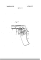
- FIG. 7 shows a modification of the instrument of FIG.
- FIG. 8 is a partial view in axial section of a second embodiment of the instrument according to the invention.
- FIG. 9 is an elevation view, partly broken away, of a third embodiment of the instrument according to the invention.
- FIG. 9a shows a partial view in axial section ofa modification of the embodiment of the instrument of FIG.
- FIG. 10 shows an elevation view, partly broken away, of a fourth embodiment of the instrument according to the invention.
- FIG. 10a shows a partial view in axial section of a modification of the embodiment of the instrument of FIG. 10;
- FIG. 11 is a partial elevation view, partly broken away, of a fifth embodiment of the instrument according to the invention.
- FIG. 12 is an elevation view, partly broken away, of a sixth embodiment of the invention.
- FIG. 13 is a section along line XIIIXIII of FIG. 12;
- FIG. 14 is a section along line XIV-XIV of FIG. 12;
- FIG. 15 is an elevation view, partly broken away, of an advantageous embodiment of the instrument according to the invention, lodged in a cavity containing a structure to be ligated.
- the surgical instrument according to the invention comprises a tube 1 having the form ofa truncated cone and is of a length which is greater than the depth of a cavity containing a structure to be ligated.
- a tube 1 having the form ofa truncated cone and is of a length which is greater than the depth of a cavity containing a structure to be ligated.
- the tube 1 has a length which is greater than the length of the oesophagus up to the cardia.
- the tube 1 is fixed at one extremity to a handle 4 directed rearward and downward.
- This handle is shaped substantially like the butt of a gun in order to facilitate its gripping by the hand. For this purpose it presents advantageously at the front portion recesses 5 for lodging the fingers and rearwardly a recess 31 for the ball of the thumb.
- a tube 2 is mounted for sliding movement on the inside of tube 1. It presents at the rear portion an abutment 15 designed to rest against the rear extremity of the outer tube 1 when it is received completely in tube 1.
- the inner tube 2 is slightly longer than the outer tube 1 so as to present a part 14 protruding in front of tube 1 when it is received fully in tube 1.
- This forward part 14 of tube 2 is designed to receive one or more elastic cords 29 to ligate an internal structure, in this case a hemorrhoid.
- An arrow shaped groove 6 is cut into handle 4 at its upper part and extends from the rear to the front and upwardly.
- the groove 6 provides a channel for a lever 3 fixed to the rear extremity of the inner tube 2 and extending downwardly.
- the position of lever 3 on tube 2 and its form are arranged so that when tube 2 is received completely in tube 1 this lever 3 protrudes forwardly from the handle 4 like the trigger of a gun.
- Tube 2 is usually received completely in tube 1 by means of a spring blade 9 mounted on a support or base 10 and arranged in a recess 8 of handle 4 so as to be applied elastically against lever 3.
- the recess 8 extends preferably up to the lower extremity of handle 4 in order to permit the retraction of blade 9 from this recess so that tube 2 may be withdrawn and pulled from tube 1.
- a slot 1 1 may be cut into the support 10 to allow the insertion of a finger nail in order to facilitate the withdrawal of the spring blade 9.
- the instrument of FIGS. 1 and 2 is equipped with an illuminating device for the inside of tube 2.
- the outer tube 1 carries at its rear portion a lateral bushing 17 directed obliquely rearwardly and provided with an electric bulb 20.
- the outer tube 1 is perforated to provide an opening 18 and the inner tube 2 is perforated to provide an opening 19 having the form of a button hole which is elongated in the axial direction of tubes 1 and 2.
- the length of this opening 19 is chosen so as to assure constantly the illumination of the inside of tube 2 from the bulb 20 while tube 2 is received in tube 1 for a length which is equal to its forward part 14 which projects in front of tube 1.
- the inner partition of tube 2 is preferably polished so as to reflect the light beams emanating from bulb 20 forwardly of tube 17.
- FIGS. 1 and 2 The surgical instrument represented in FIGS. 1 and 2 is utilized without anesthesia in the following manner:
- auxiliary member such as represented in FIG. 3.
- This auxiliary member comprises according to the invention a conical part 21 followed by a cylindrical part 22 whose diameter is essentially equal to the outer diameter of the forward part 14 of tube 2.
- a cylindrical extension 23 is integral with part 22 and may be engaged into the forward part 14 of tube 2, in order to hold the auxiliary member against this tube.
- a shoulder 80 is provided on the cylindrical part 22 around the cylindrical extension 23 in order to permit the engagement of the beveled forward edge of tube 2. In this manner the passing of an elastic cord 29 from the cylindrical part 22 on the forward part 14 of tube 2 is facilitated.
- a stopper bar 28 (shown in FIG. 4) is introduced from the back into groove or recess 6 until its rear abutment 30 is in position against the rear extremity of tube 2, its forward extremity 26 formed like a pointed arch whose diameter is essentially the same as the inner diameter of groove or recess 6 protruding in that position from the front of tube 2.
- a handle 27 facilitates the gripping of the stopper bar 28 and its introduction into tube 2.
- the operator may thereafter introduce the instrument into cavity 32 containing the structure to be treated for example into the rectal cavity through the anus (FIG. 5).
- the operator may easily observe cavity 32 and the structure 34 to be ligated through tube 2 as through an endoscope, the bulb having been illuminated in the lateral bushing 17.
- the operator holds handle 4 of the instrument firmly in one hand he introduces with the other hand an atraumatic clamp 33 through tube 2 in order to seize the structure 34 to be ligated (for example a hemorrhoid or a polyp) and drawing it on the inside of tube 2.
- the operator actuates subsequently lever 3 in the direction of arrow X (FIG.
- the elongated lateral opening 19 provided through the partition of the inner tube 2 permits an illumination of the inside of this tube from bushing 17 for the entire duration of the operation even after the operator has actuated lever 3.
- FIG. 6 a modification of the instrument of FIGS. 1 and 2 is illustrated.
- the inner tube 2 is made of a transparent material, for example glass. In this manner the requirement of making an opening 19 for the propagation of the light beams emanating from the light source 20 is eliminated.
- this tube 2 may advantageously constitute, with a sufficient inclination of bushing 17, a propagation center of the light beams toward the structure to be ligated.
- the forward part 14 of transparent tube 2 may be formed by a coaxial sleeve 35 extending the outer face of this tube (FIG. 7) forwardly.
- This sleeve 35 prevents the deposit of soiling substances on the forward extremity of the transparent tube 2.
- a rearward ring 37 may be provided in this case in order to assure an adequate sliding of this tube 2 in the outer tube 1.
- the sleeve 35 may also be extended if desired as far as the bushing 17 and perforated opposite the bushing to provide an opening in the form of a button hole similar to opening 19 of the instrument shown in FIGS. 1 and 2.
- the two faces, the inner face and the outer face, of the transparent tube 2 may be covered by a jacket or a metallic film, for example a tin film, in order to prevent a diffusion of the light from the tube 2.
- the lateral bushing 17 may, in a modification, contain a mass of bundled optical fibers, for example glass fibers, suitable of constituting a propagation center of the light beams toward the tube 2.
- FIG. 8 is represented partially a particular embodiment of the instrument according to the invention permitting an intense illumination of the examined cavity and the structure to be ligated.
- the instrument is provided with a sleeve 38 which is designed to be locked or screwed in the back part of the inner tube 2.
- This sleeve 38 is perforated laterally to form an opening 18 around which a lateral bushing 17 is fixed.
- On the threaded extremity of this bushing 17 the extremity of a flexible tube 39 is screwed which is connected to an intense light source not shown.
- This intense light source may, for example, be produced by means of an electric are.
- a mass of bundled optical fibers is disposed in the flexible tube 39 and bushing 17.
- This mass of optical fibers is connected to a ring 68 disposed on the inside of sleeve 38 and made of a transparent material, susceptible of propagating a light beam, for example of glass.
- This ring is advantageously formed by the prolongation of the optical fibers contained in bushing 17. Its inner face, which is directed toward the axis of tube 2, may be covered by a partition or metallic film to avoid a parasitic diffusion of the light.
- the inner tube 2 of the instrument according to the invention is shorter than the outer tube 1 and disposed in the forward part of the latter.
- the tube 2 is fixed to a rod 40 traversing the tube 1 preferably along its wall and bent at 41 in the rearward portion.
- the bent portion 41 of rod 40 is urged by the effect of spring 42 against a lever 43 and an abutment 44 which is integral with the handle 4.
- the lever 43 is pivotally mounted at 45 on handle 4 and is designed to be actuated at 46 in the direction of the arrow Y by the thumb of the hand holding the handle 4 so as to withdraw the rod 40 and the tube 2 against the force of spring 42.
- stopper bar 28 (not shown) must necessarily present a longitudinal groove for the travel of rod 40.
- a longitudinal groove may be cut into the wall of the outer tube 1 to provide a passage for rod 14 so that this rod does not extend into tube 1.
- the aforementioned groove of the stopper bar 28 is no longer necessary.
- FIG. 9a is a section view of a partial modification of the instrument of FIG. 9 in which the outer tube has in its forward part a suitable diameter to allow the sliding of tube 2 and in its rearward part internal conical walls which facilitate the illumination, the examination and the introduction of a clamp.
- the rod 40 is angled in accordance with tube 2 and the stopper bar is adapted to the diameters of tubes 1 and 2.
- the rearward part of tube 1 may be modified to have an oval or flared shape.
- the inner tube 2 has a greater length than the depth of the aforementioned cavity up to the structure to be ligated. It is fixed in the back on a handle 4 which is analogous to the handle used with the instruments described above.
- the outer tube 1 is mounted for sliding movement around the forward part 14 of the inner tube 2.
- a rod 49 is fixed to tube 1 and disposed along the inner face of tube 2.
- An elongated opening 47 is cut into the wall of tube 2 facing tube 1 to provide a passage of the forward bent part of rod 49. This opening 47 extends preferably up to the forward extremity of tube 2 so as to permit the removal of tube 1 as described above.
- the rod 49 is extended in the back by means of a bent portion 50 arranged in an arrow shaped recess 6 cut into the upper part of the handle 4 and extending upwardly and rearwardly.
- the grip member of the instrument comprises a lever 54 rotated on a pivot 55 of handle 4 and interposed between the bent portion 50 and a fixed abutment 56.
- the lower part of the lever 54 traverses the recess 6 in front of the handle so that it can be actuated by a finger of the hand in the direction of the arrow Y.
- the tube 1 is returned to the rear by means of a spring 51 disposed in a tubular slot 52 of the handle 4 and compressed against the aforementioned bent portion 50.
- a screw 54 permits access to spring 51.
- the bent portion 50 is preferably fixed to rod 49 by means of a threaded sleeve 57 so as to permit the removal of tube 1 for the purpose of cleaning the instrument.
- FIG. 10a shows a section of a partial modification of the embodiment of the instrument of FIG. 10, in which the inner tube 2 presents at its forward part a diameter suitable to permit a sliding of tube 1 and at its rear part internal conical walls.
- the rod 49 is angled to correspond with tube 1 and is lodged in a groove cut into tube 2.
- the rear part of tube 2 may also have an oval or flared shape.
- the instrument according to the invention comprises a handle 4 fixed to the rear part of outer tube 1 whose length is greater than the depth of the cavity to be examined.
- the inner tube 2 is extended at the back of tube 1 by an abutment 69.
- a spring 70 is compressed between this abutment 69 and an abutment 71 fixed to tube 1 or to handle 4 so as to urge tube 2 toward the back into tube 1.
- a rod 72 is mounted for sliding movement in a slot 73 of handle 4.
- a spring 74 is interposed between the bottom of slot 73 and rod 72 so as to urge rod 72 against a wall portion 75 of the inner tube 2 where it constitutes an abutment preventing a withdrawal of tube 2 under the effect of spring 70.
- a lever 76 urged by a spring 77 so as to extend forwardIy of the handle 4 carries a beveled element 78 arranged against a wall portion 79 of the rod or abutment 72.
- FIGS. 12, 13 and 14 show a particularly interesting embodiment of the instrument according to the invention in which the assembly of the two tubes 1 and 2 is fixed so as to be removable from handle 4.
- the outer tube 1 carries adjacent its rear extremity a longitudinal rib 58 presenting in transverse section a dove tail shape.
- the handle 4 which can be made for example of steel and similar to the handle of the instruments shown in FIGS. 1 and 2, presents in its upper part a reinforced forward zone 59 to support the rear part of tube 1.
- a longitudinal groove 60 of dove tail shape is provided in this part 59 in order to engage the corresponding rib 58 of tube 1.
- Abutments 61 assure the proper engagement of the tubes 1 and 2 on the handle 4.
- the upper forward zone 59 of the handle 4 is perforated in the axis of the groove 60 by a slit 68 for the passage oflever 3 fixed to tube 2.
- a slit 68 for the passage oflever 3 fixed to tube 2.
- This embodiment of the instrument according to the invention allows to make all the tubes of an inexpensive material, for example of synthetic material, in which case the tubes would be used only one time. They may be furnished already disposed one inside the other with an elastic band 29 placed around the extremity of tube 2, and completely enclosed in a sterilized package.
- FIG. 15 concerns an embodiment which is particularly advantageous for a surgical instrument according to the invention.
- the tubes 1 and 2 are extended toward the back by means of a sleeve 62 locked or threaded into the back part 15 of tube 2.
- This sleeve 62 is closed by a transparent screen 63 made for example of glass.
- a joint 64 may be provided to assure a good seal between the screen 63 and the sleeve 62.
- the sleeve 62 is perforated to form a lateral opening 65 and a bent connecting tube 66 is attached to the periphery of this opening.
- the tube 66 is adapted to be connected to a flexible tube 67 which communicates with a vacuum pump not shown.
- the transparent screen permits an observation of this cavity and orienting the instrument carefully so that the extremity 14 of tube 2 is placed in the vicinity of a structure 34 to be ligated.
- the vacuum pump may be actuated which results in pulling the structure 43 into tube 2.
- a manometer not shown may be mounted on tube 67 and permits to regulate the vacuum in the cavity to the optimum value.
- the instrument according to the invention illustrated in FIG. allows the operator to work without a clamp whose atraumatic character is only relative and therefore leaves him one hand free. Furthermore, this instrument permits making the ligature operation less coarse. It permits further a control of the bleeding tendency of the blood vessels in the cavity, for example of the hemorrhoids, by measuring the vacuum capable of provoking a bleeding in the cavity.
- a surgical instrument for ligating internal structures such as hemorrhoids and the like within a cavity of the human body by the application of at least one elastic cord comprising, in combination:
- an outer hollow tube having a forward end and a rearward end
- an inner hollow tube having a forward end and a rearward end and coaxially and slidably received within the outer hollow tube wherein the length of at least one tube exceeds the depth of the body cavity up to the structure to be ligated, said rearward end of the inner tube being open;
- said inner tube further including means for passing illuminating light therethrough;
- handle means associated with the rear-ward ends of the outer and inner tubes;
- the trigger means is secured to the inner tube and is movably received within the channel.
- a spring blade disposed within the recess for biasing the trigger means so that the inner tube is pushed in a forward direction.
- the handle member is fixed to said outer tube and comprises a spring disposed between said inner and said outer tube to urge said inner tube in a rearward direction against an abutment so as to maintain the inner tube in a position wherein its forward end is located forwardly of the outer tube forward end, and where in said abutment is retractable against a spring force by a trigger mounted on said handle member.
- spring means for biasing the other end of the rod against the pivotal lever so that the outer tube is urged in a rearward direction.
- the inner tube has a smaller length than the depth of said cavity up to the structure to be ligated;
- the outer tube has a forward portion adapted to slidably receive the inner tube and a conical portion increasing in diameter rearwardly'.
- the outer tube includes a longitudinal rib of dovetail shape for engagement within the groove.
- the instrument of claim 1 including removable dilating means for facilitating the introduction of the associated tubes with the elastic cord into the cavity containing the structure to be ligated.
- an illumination source associated with the hollow projection for illuminating the structure to be ligated.
- both tubes have a length greater than the depth of said cavity up to the structure to be ligated and the hollow projection is formed on the outer tube.
- the inner tube is made of a transparent material to permit propagation of light beams from said light source into the inner tube.
- the instrument according to claim 1 further including a sleeve secured to the rearward end of the inner tube, said sleeve having a laterally extending hollow portion for connection to an intense light source.
Abstract
A surgical instrument for ligating internal structures of a cavity in the human body, such as internal hemorrhoids, by means of at least one elastic cord comprises two tubes mounted for relative sliding movement one inside the other, the inner tube protruding at the front of the outer tube. A grip member is connected to one of said two tubes and has actuating means to produce a relative displacement of the outer tube forwardly relative to the inner tube. The outer tube and/or the inner tube has a greater length than the depth of the cavity up to the structure to be ligated, so that it constitutes an endoscope.
Description
United States Patent -191 Van Hoorn 1 Sept. 25, 1973 [54] SURGICAL LIGATING INSTRUMENT OF 3,155,094 11/1964 Hamilton............... 128/326 THE ENDOSCOPE TYPE 3,547,124 12/1970 ,Fergusson.... 128/326 3,687,138 8/1972 128/326 [76] Inventor:
k .1 w a I.
Marc E. J. Van Hoorn, 197 Avenue Winston Churchill, Bruxelles, Belgium Dec. 7, 1971 Primary ExaminerAldrich F Mcdbery AttorneyJohn J. Dennemeyer [22] Filed:
[57] ABSTRACT A surgical instrument for ligating internal structures of 21 1 Appl. No.: 205,555
Foreign Application Priority Data Dec. 11
[30] a cavity in the human body, such as internal hemorrhoids, by means of at least one elastic cord comprises two tubes mounted for relative sliding movement one inside the other, the inner tube protruding at the front of the outer tube. A grip member is connected to one June 1, Belgium...............................
of said two tubes and has actuating means to produce a relative displacement of the outer tube forwardly relative to the inner tube. The outer tube and/or the inner tube has a greater length than the depth of the cavity Una up to the structure to be ligated, sothat it constitutes an endoscope.
[56] References Cited UNITED STATES PATENTS 2,942,604 6/1960 Gravlee, Jr. 128/303 A 24 Claims, 17 Drawing Figures PATENTED SEPZS I915 SHEET 1 IF 8 SHEET 2 [IF 8 PATENTEnstPzslau PAIENTEUSEPZSISB SHEET 7 [IF 8 PATENTED8EP25|975 3,760,810
SHEET 8 OF 8 SURGICAL LIGATING INSTRUMENT OF THE ENDOSCOPE TYPE The present invention relates to the treatment of internal and external parts or structures of the human body by means of a ligature and concerns more particularly the treatment of rectosigmoidal lesions such as the hemorrhoids.
It is already known to treat the internal hemorrhoids by ligating them by means of one or several elastic cords to produce a stoppage of the circulation and causing the deadening of the hemorrhoid tissues.
The invention concerns a surgical instrument to ligate even without anesthesia the internal parts of a cavity of the human body, more particularly internal hemorrhoids, by means of at least one elastic cord, and comprises in a known manner two tubes mounted in sliding relationship one inside the other, the inner tube projecting from the forward portion of the outer tube, and a handle or grip member connected to two tubes in order to produce a relative movement of the outer tube forwardly with respect to the inner tube.
The use of a known instrument of this type by a surgeon on the inside of a cavity in which a structure is to be ligated, particularly at the inside of the anal canal, in combination with an atraumatic clamp for taking hold of the structure to be treated, necessitates a visual observation of this structure and of the entire operation at the inside of the cavity. In order to permit this observation a separate endoscope has been used which is held by the assistant of the surgeon while the latter proceeds with his work of effecting a ligature of the structure.
The known instruments present thus the disadvantage of requiring the continuous presence of an assistant during the entire surgical operation. This assistant is reduced to a passive function. He cannot observe personally the cavity and the ligature operation which takes place, due to the relatively narrow visual field of the endoscope. It is therefore difficult for the assistant to determine which position of the endoscope is the most helpful to the surgeon and therefore the surgeon may be impeded in his handling of the surgical instrument and of the atraumatic clamp.
An additional disadvantage of these known instruments which must necessarily be utilized jointly with an endoscope resides in the fact that they reduce to an appreciable extent the visual field of the endoscope which they traverse. This constitutes a supplemental impediment for the surgeon.
The present invention eliminates these inconveniences. For this'purpose the outer tube and/or the inner tube of the surgical instrument according to the invention has a length which is greater than the depth of the cavity up to the structure to be ligated.
The instrument according to the invention thus constitutes an endoscope in the sense that the surgeon is able to observe the inside of the cavity and structure to be ligated directly through the two tubes of which one at least projects out of the cavity. The instrument according to the invention presents thus the advantage of combining in a single device which can be operated with one hand at the same time a surgical instrument for ligating an internal structure and also an endoscope. The instrument according to the invention thus relieves the surgeon from the requirement of a separate endoscope and an assistant for handling it. Furthermore, the
doctor may easily orientthe instrument to the position which appears to him the most favorable to observe and seize the structure to be ligated which constitutes a supplemental advantage in relation to the known instruments used with a separate endoscope as described above.
in the particular case concerning the treatment of the internal hemorrhoids the outer tube and/or the inner tube of the instrument according to the invention has a length which is greater than the length of the anal,
canal so as to constitute a rectoscope.
A supplemental advantage of the instrument according to the invention resides in the fact that the endoscope which it constitutes is traversed by no other instrument except the atraumatic clamp. He obtains thus a relatively large visual field which is particularly due to the fact that he is independent of the dimensions of the conventional endoscopes and that the section of the tubes may have partly, entirely, or in a combination, depending on the requirement, a cylindrical, oval, conical or flaring form. Simultaneously the diameter of the sliding tubes may be essentially greater than the diameter of the sliding tubes of the known instruments so that in comparison with the known instruments, the instrument according to the invention permits a more substantial introduction of tissue into the tube and ligating more tissue constituting the structure to be treated.
In certain particular cases, especially for the treatment of internal hemorrhoids the surgeon may sometimes even discard the atraumatic clamp because the hemorrhoid to be ligated may protrude into the inner tube of the instrument according to the invention due to an abdominal hypertension on the part of the patient.
In a particularlyadvantageous embodiment of the instrument according to the invention the two aforementioned tubes are closed at their rear extremity by a transparent partition and they are in communication with a vacuum pump.
This particular embodiment of the instrument according to the invention allows the surgeon to operate without the atraumatic clamp because the structure to be ligated is pulled into the inner tube of the instrument under the action of the vacuum pump.
This embodiment of the instrument according to the invention allows also, in combination with a manometer, to determine at what vacuum a vascular rupture is produced. 1
According to a preferred embodiment of the instrument according to the invention the grip member comprising a handle which is designed so that the hand can be placed around it, this handle being fixed to the extremity of one of the two aforementioned tubes which has a greater length than the depth of the cavity and as far as the structure to be ligated and furthermore a lever which is connected to the other tube and which is arranged so that it can be actuated by a finger of that hand. This embodiment is advantageous in that it permits to take a stronger hold of the instrument and therefore a more precise functioning.
During the utilization of the instrument according to the invention the illumination of the cavity and of the structure to be ligated may be obtained for example by ambiant light in the operating room or also by means of a frontal lamp of the conventional type carried by the surgeon.
According to a particular embodiment the instrument according to the invention is provided with an illuminating device for the cavity and the structure to be ligated. This illuminating device can for example comprise a bushing which is fixed transversely to one of the tubes and which is in communication both with a light source and with the inside of the tubes.
The characteristic features and greater details of the invention will become more clearly apparent from the following description given with reference to the attached drawings which represent, for the purpose of example only, several specific embodiments of the instrument according to the invention. In the drawings:
FIG. 1 shows an elevation view, partly broken away, of a first embodiment of the instrument according to the invention;
FIG. 2 is a section along line IIII of FIG. 1;
FIG. 3 is an elevation view, partly in section, of an auxiliary part of the instrument according to the invention;
FIG. 4 is an elevation view of an other auxiliary part of the instrument according to the invention;
FIG. 5 shows the instrument of FIGS. 1 and 2 lodged in a cavity containing a structure to be ligated, and utilized jointly with an atraumatic clamp;
FIG. 6 is a view similar to FIG. 2 of a modification of the embodiment of the instrument of FIGS. 1 and 2;
FIG. 7 shows a modification of the instrument of FIG.
FIG. 8 is a partial view in axial section of a second embodiment of the instrument according to the invention;
FIG. 9 is an elevation view, partly broken away, of a third embodiment of the instrument according to the invention;
FIG. 9a shows a partial view in axial section ofa modification of the embodiment of the instrument of FIG.
FIG. 10 shows an elevation view, partly broken away, of a fourth embodiment of the instrument according to the invention;
FIG. 10a shows a partial view in axial section of a modification of the embodiment of the instrument of FIG. 10;
FIG. 11 is a partial elevation view, partly broken away, of a fifth embodiment of the instrument according to the invention;
FIG. 12 is an elevation view, partly broken away, of a sixth embodiment of the invention;
FIG. 13 is a section along line XIIIXIII of FIG. 12;
FIG. 14 is a section along line XIV-XIV of FIG. 12;
FIG. 15 is an elevation view, partly broken away, of an advantageous embodiment of the instrument according to the invention, lodged in a cavity containing a structure to be ligated.
Referring to the drawings, like numerals designate like parts throughout the different views. According to a first embodiment of the invention represented in FIGS. 1 and 2 the surgical instrument according to the invention comprises a tube 1 having the form ofa truncated cone and is of a length which is greater than the depth of a cavity containing a structure to be ligated. For example in the particular case of an instrument to be used for ligating internal structures in the sigmoidal flexure of the colon, such as internal hemorrhoids, the
canal. In the case of an instrument to be used for ligating structures of the oesophagus, such as the polyps, the tube 1 has a length which is greater than the length of the oesophagus up to the cardia.
The tube 1 is fixed at one extremity to a handle 4 directed rearward and downward. This handle is shaped substantially like the butt of a gun in order to facilitate its gripping by the hand. For this purpose it presents advantageously at the front portion recesses 5 for lodging the fingers and rearwardly a recess 31 for the ball of the thumb.
A tube 2 is mounted for sliding movement on the inside of tube 1. It presents at the rear portion an abutment 15 designed to rest against the rear extremity of the outer tube 1 when it is received completely in tube 1. The inner tube 2 is slightly longer than the outer tube 1 so as to present a part 14 protruding in front of tube 1 when it is received fully in tube 1. This forward part 14 of tube 2 is designed to receive one or more elastic cords 29 to ligate an internal structure, in this case a hemorrhoid.
An arrow shaped groove 6 is cut into handle 4 at its upper part and extends from the rear to the front and upwardly. The groove 6 provides a channel for a lever 3 fixed to the rear extremity of the inner tube 2 and extending downwardly. The position of lever 3 on tube 2 and its form are arranged so that when tube 2 is received completely in tube 1 this lever 3 protrudes forwardly from the handle 4 like the trigger of a gun. Tube 2 is usually received completely in tube 1 by means of a spring blade 9 mounted on a support or base 10 and arranged in a recess 8 of handle 4 so as to be applied elastically against lever 3. The recess 8 extends preferably up to the lower extremity of handle 4 in order to permit the retraction of blade 9 from this recess so that tube 2 may be withdrawn and pulled from tube 1. A slot 1 1 may be cut into the support 10 to allow the insertion of a finger nail in order to facilitate the withdrawal of the spring blade 9.
The instrument of FIGS. 1 and 2 is equipped with an illuminating device for the inside of tube 2. For this purpose the outer tube 1 carries at its rear portion a lateral bushing 17 directed obliquely rearwardly and provided with an electric bulb 20. Opposite bushing 17 the outer tube 1 is perforated to provide an opening 18 and the inner tube 2 is perforated to provide an opening 19 having the form of a button hole which is elongated in the axial direction of tubes 1 and 2. The length of this opening 19 is chosen so as to assure constantly the illumination of the inside of tube 2 from the bulb 20 while tube 2 is received in tube 1 for a length which is equal to its forward part 14 which projects in front of tube 1. The inner partition of tube 2 is preferably polished so as to reflect the light beams emanating from bulb 20 forwardly of tube 17.
The surgical instrument represented in FIGS. 1 and 2 is utilized without anesthesia in the following manner:
When the inner tube 2 is drawn fully into outer tube 1 under the action of spring 9, one or more elastic cords 29 are placed around the forward part 14 of tube 2 which protrudes at the front of outer tube 1. For this purpose one may advantageously make use 'of an auxiliary member such as represented in FIG. 3. This auxiliary member comprises according to the invention a conical part 21 followed by a cylindrical part 22 whose diameter is essentially equal to the outer diameter of the forward part 14 of tube 2. A cylindrical extension 23 is integral with part 22 and may be engaged into the forward part 14 of tube 2, in order to hold the auxiliary member against this tube. A shoulder 80 is provided on the cylindrical part 22 around the cylindrical extension 23 in order to permit the engagement of the beveled forward edge of tube 2. In this manner the passing of an elastic cord 29 from the cylindrical part 22 on the forward part 14 of tube 2 is facilitated.
As soon as one or several elastic cords 29 have been placed on the extremity 14 of tube 2 the auxiliary member of FIG. 3 is withdrawn and thereafter a stopper bar 28 (shown in FIG. 4) is introduced from the back into groove or recess 6 until its rear abutment 30 is in position against the rear extremity of tube 2, its forward extremity 26 formed like a pointed arch whose diameter is essentially the same as the inner diameter of groove or recess 6 protruding in that position from the front of tube 2. A handle 27 facilitates the gripping of the stopper bar 28 and its introduction into tube 2.
The operator may thereafter introduce the instrument into cavity 32 containing the structure to be treated for example into the rectal cavity through the anus (FIG. 5). After having withdrawn the stopper bar 28 the operator may easily observe cavity 32 and the structure 34 to be ligated through tube 2 as through an endoscope, the bulb having been illuminated in the lateral bushing 17. While the operator holds handle 4 of the instrument firmly in one hand he introduces with the other hand an atraumatic clamp 33 through tube 2 in order to seize the structure 34 to be ligated (for example a hemorrhoid or a polyp) and drawing it on the inside of tube 2. The operator actuates subsequently lever 3 in the direction of arrow X (FIG. 1), against the effect of spring 9 by means of the index finger of the hand gripping handle 4, in the same manner as if he pressed the trigger of a gun. This produces a retraction of tube 2 to the inside of tube 1, so that the elastic cord 29 is pushed beyond tube 2 and closes around structure 34.
The elongated lateral opening 19 provided through the partition of the inner tube 2 permits an illumination of the inside of this tube from bushing 17 for the entire duration of the operation even after the operator has actuated lever 3.
In FIG. 6 a modification of the instrument of FIGS. 1 and 2 is illustrated.
In the instrument shown in this FIG. 6 the inner tube 2 is made of a transparent material, for example glass. In this manner the requirement of making an opening 19 for the propagation of the light beams emanating from the light source 20 is eliminated. In choosing for tube 2 a transparent material having a refraction index which is higher than that of air, for example glass, this tube 2 may advantageously constitute, with a sufficient inclination of bushing 17, a propagation center of the light beams toward the structure to be ligated.
If necessary the forward part 14 of transparent tube 2 may be formed by a coaxial sleeve 35 extending the outer face of this tube (FIG. 7) forwardly. This sleeve 35 prevents the deposit of soiling substances on the forward extremity of the transparent tube 2. A rearward ring 37 may be provided in this case in order to assure an adequate sliding of this tube 2 in the outer tube 1.
The sleeve 35 may also be extended if desired as far as the bushing 17 and perforated opposite the bushing to provide an opening in the form of a button hole similar to opening 19 of the instrument shown in FIGS. 1 and 2.
In a modification the two faces, the inner face and the outer face, of the transparent tube 2 may be covered by a jacket or a metallic film, for example a tin film, in order to prevent a diffusion of the light from the tube 2.
In the embodiments of FIGS. 1, 2 and 6 the lateral bushing 17 may, in a modification, contain a mass of bundled optical fibers, for example glass fibers, suitable of constituting a propagation center of the light beams toward the tube 2.
In FIG. 8 is represented partially a particular embodiment of the instrument according to the invention permitting an intense illumination of the examined cavity and the structure to be ligated. For this purpose the instrument is provided with a sleeve 38 which is designed to be locked or screwed in the back part of the inner tube 2. This sleeve 38 is perforated laterally to form an opening 18 around which a lateral bushing 17 is fixed. On the threaded extremity of this bushing 17 the extremity of a flexible tube 39 is screwed which is connected to an intense light source not shown. This intense light source may, for example, be produced by means of an electric are. In order to permit the propagation of the light beams toward tube 2 a mass of bundled optical fibers is disposed in the flexible tube 39 and bushing 17. This mass of optical fibers is connected to a ring 68 disposed on the inside of sleeve 38 and made of a transparent material, susceptible of propagating a light beam, for example of glass. This ring is advantageously formed by the prolongation of the optical fibers contained in bushing 17. Its inner face, which is directed toward the axis of tube 2, may be covered by a partition or metallic film to avoid a parasitic diffusion of the light.
In the embodiment shown in FIG. 9 the inner tube 2 of the instrument according to the invention is shorter than the outer tube 1 and disposed in the forward part of the latter. The tube 2 is fixed to a rod 40 traversing the tube 1 preferably along its wall and bent at 41 in the rearward portion. The bent portion 41 of rod 40 is urged by the effect of spring 42 against a lever 43 and an abutment 44 which is integral with the handle 4. The lever 43 is pivotally mounted at 45 on handle 4 and is designed to be actuated at 46 in the direction of the arrow Y by the thumb of the hand holding the handle 4 so as to withdraw the rod 40 and the tube 2 against the force of spring 42. v
In this second embodiment of the surgical instrument according to the invention the stopper bar 28 (not shown) must necessarily present a longitudinal groove for the travel of rod 40.
In a modification a longitudinal groove may be cut into the wall of the outer tube 1 to provide a passage for rod 14 so that this rod does not extend into tube 1. In this case the aforementioned groove of the stopper bar 28 is no longer necessary.
According to an other modification of the surgical instrument according to FIG. 9 the handle 4 shows in its upper part an arrow shaped recess similar to recess 6 of the embodiment of FIGS. 1 and 2. The bent portion 41 of rod 40 traverses this recess so as to extend forwardly from handle 4 in a manner of a gun trigger. The spring 42 may in this case be advantageously replaced by a spring which is similar to flexible blade 9 of the embodiment of FIGS. 1 and 2.
FIG. 9a is a section view of a partial modification of the instrument of FIG. 9 in which the outer tube has in its forward part a suitable diameter to allow the sliding of tube 2 and in its rearward part internal conical walls which facilitate the illumination, the examination and the introduction of a clamp. The rod 40 is angled in accordance with tube 2 and the stopper bar is adapted to the diameters of tubes 1 and 2. The rearward part of tube 1 may be modified to have an oval or flared shape.
FIG. shows a special embodiment of the instrument according to the invention in which the outer tube has a smaller length than the depth of the cavity containing the structure to be ligated.
In the instrument of FIG. 10 the inner tube 2 has a greater length than the depth of the aforementioned cavity up to the structure to be ligated. It is fixed in the back on a handle 4 which is analogous to the handle used with the instruments described above.
The outer tube 1 is mounted for sliding movement around the forward part 14 of the inner tube 2.
A rod 49 is fixed to tube 1 and disposed along the inner face of tube 2. An elongated opening 47 is cut into the wall of tube 2 facing tube 1 to provide a passage of the forward bent part of rod 49. This opening 47 extends preferably up to the forward extremity of tube 2 so as to permit the removal of tube 1 as described above.
The rod 49 is extended in the back by means of a bent portion 50 arranged in an arrow shaped recess 6 cut into the upper part of the handle 4 and extending upwardly and rearwardly.
The grip member of the instrument comprises a lever 54 rotated on a pivot 55 of handle 4 and interposed between the bent portion 50 and a fixed abutment 56. The lower part of the lever 54 traverses the recess 6 in front of the handle so that it can be actuated by a finger of the hand in the direction of the arrow Y.
The tube 1 is returned to the rear by means of a spring 51 disposed in a tubular slot 52 of the handle 4 and compressed against the aforementioned bent portion 50. A screw 54 permits access to spring 51.
The bent portion 50 is preferably fixed to rod 49 by means of a threaded sleeve 57 so as to permit the removal of tube 1 for the purpose of cleaning the instrument.
The FIG. 10a shows a section of a partial modification of the embodiment of the instrument of FIG. 10, in which the inner tube 2 presents at its forward part a diameter suitable to permit a sliding of tube 1 and at its rear part internal conical walls. The rod 49 is angled to correspond with tube 1 and is lodged in a groove cut into tube 2. The rear part of tube 2 may also have an oval or flared shape.
In the embodiment according to 'FIG. 11 the instrument according to the invention comprises a handle 4 fixed to the rear part of outer tube 1 whose length is greater than the depth of the cavity to be examined. The inner tube 2 is extended at the back of tube 1 by an abutment 69. A spring 70 is compressed between this abutment 69 and an abutment 71 fixed to tube 1 or to handle 4 so as to urge tube 2 toward the back into tube 1.
A rod 72 is mounted for sliding movement in a slot 73 of handle 4. A spring 74 is interposed between the bottom of slot 73 and rod 72 so as to urge rod 72 against a wall portion 75 of the inner tube 2 where it constitutes an abutment preventing a withdrawal of tube 2 under the effect of spring 70.
A lever 76 urged by a spring 77 so as to extend forwardIy of the handle 4 carries a beveled element 78 arranged against a wall portion 79 of the rod or abutment 72.
In order to move the lever 76 in the direction of the arrow Z the beveled element 78 pushes rod 72 against the force of return spring 74 and moves it away from the retaining wall 75 to liberate thus tube 2 which may return freely into the outer tube 1 under the effect of spring 70.
The return of tube 2 into tube 1 is limited by the abutment 69 cooperating with the rod 72.
The FIGS. 12, 13 and 14 show a particularly interesting embodiment of the instrument according to the invention in which the assembly of the two tubes 1 and 2 is fixed so as to be removable from handle 4.
For this purpose the outer tube 1 carries adjacent its rear extremity a longitudinal rib 58 presenting in transverse section a dove tail shape.
The handle 4,which can be made for example of steel and similar to the handle of the instruments shown in FIGS. 1 and 2, presents in its upper part a reinforced forward zone 59 to support the rear part of tube 1. A longitudinal groove 60 of dove tail shape is provided in this part 59 in order to engage the corresponding rib 58 of tube 1. Abutments 61 assure the proper engagement of the tubes 1 and 2 on the handle 4.
The upper forward zone 59 of the handle 4 is perforated in the axis of the groove 60 by a slit 68 for the passage oflever 3 fixed to tube 2. In this manner the assembly of the two tubes 1 and 2 locked one inside the other may be put in position on handle 4 by a single movement from front to back. This assembly may in an analogous manner be withdrawn from handle 4 witha single back to front movement.
This embodiment of the instrument according to the invention allows to make all the tubes of an inexpensive material, for example of synthetic material, in which case the tubes would be used only one time. They may be furnished already disposed one inside the other with an elastic band 29 placed around the extremity of tube 2, and completely enclosed in a sterilized package.
FIG. 15 concerns an embodiment which is particularly advantageous for a surgical instrument according to the invention.
In the instrument of FIG. 15 the tubes 1 and 2 are extended toward the back by means ofa sleeve 62 locked or threaded into the back part 15 of tube 2. This sleeve 62 is closed by a transparent screen 63 made for example of glass. A joint 64 may be provided to assure a good seal between the screen 63 and the sleeve 62.
The sleeve 62 is perforated to form a lateral opening 65 and a bent connecting tube 66 is attached to the periphery of this opening. The tube 66 is adapted to be connected to a flexible tube 67 which communicates with a vacuum pump not shown.
When the instrument of FIG. 15 is lodged in a cavity containing a structure to be ligated, for example the anal canal, the transparent screen permits an observation of this cavity and orienting the instrument carefully so that the extremity 14 of tube 2 is placed in the vicinity of a structure 34 to be ligated. The vacuum pump may be actuated which results in pulling the structure 43 into tube 2.
A manometer not shown may be mounted on tube 67 and permits to regulate the vacuum in the cavity to the optimum value.
The instrument according to the invention illustrated in FIG. allows the operator to work without a clamp whose atraumatic character is only relative and therefore leaves him one hand free. Furthermore, this instrument permits making the ligature operation less coarse. It permits further a control of the bleeding tendency of the blood vessels in the cavity, for example of the hemorrhoids, by measuring the vacuum capable of provoking a bleeding in the cavity.
It is obvious to the persons skilled in the art that the invention is not limited to the embodiments described above andthat suitable modifications may be made without leaving the scope of the invention as defined by the following claims.
What I claim is:
1. A surgical instrument for ligating internal structures such as hemorrhoids and the like within a cavity of the human body by the application of at least one elastic cord, said instrument comprising, in combination:
a. an outer hollow tube having a forward end and a rearward end;
b. an inner hollow tube having a forward end and a rearward end and coaxially and slidably received within the outer hollow tube wherein the length of at least one tube exceeds the depth of the body cavity up to the structure to be ligated, said rearward end of the inner tube being open;
c. said inner tube further including means for passing illuminating light therethrough;
d. means for retaining an elastic cord on the forward end of the inner tube while it protrudes beyond the forward end of the outer tube;
e. handle means associated with the rear-ward ends of the outer and inner tubes; and
f. means secured to the handle means for imparting a relative movement between the outer and inner tubes so that the elastic cord is caused to slide off of the forward end of the second tube and attach itself to the structure being ligated.
2. The instrument according to claim 1 wherein the means for producing the relative movement between the outer and inner tubes includes a trigger means.
3. The instrument according to claim 2 wherein the handle means includes a channel formed therein and a. the handle means is secured to .the outer tube; and
b. the trigger means is secured to the inner tube and is movably received within the channel.
4. The instrument according to claim 3 wherein the handle member includes:
a. a recess; and
b. a spring blade disposed within the recess for biasing the trigger means so that the inner tube is pushed in a forward direction.
5. The instrument according to claim 1 wherein the handle member is fixed to said outer tube and comprises a spring disposed between said inner and said outer tube to urge said inner tube in a rearward direction against an abutment so as to maintain the inner tube in a position wherein its forward end is located forwardly of the outer tube forward end, and where in said abutment is retractable against a spring force by a trigger mounted on said handle member.
6. The instrument according to claim 1 wherein the handle means is secured to the inner tube and includes:
a. a pivotal lever;
b. an actuation rod connected at its one end to the outer tube and disposed at its other end'adjacent the pivotal lever; and
0. spring means for biasing the other end of the rod against the pivotal lever so that the outer tube is urged in a rearward direction.
7. The instrument according to claim 1 wherein:
a. the inner tube has a smaller length than the depth of said cavity up to the structure to be ligated; and
b. the outer tube has a forward portion adapted to slidably receive the inner tube and a conical portion increasing in diameter rearwardly'.
8. The instrument according to claim 1 wherein the handle means is detachably secured to the outer tube.
9. The instrument according to claim 8 wherein a. the handle means includes a groove; and
b. the outer tube includes a longitudinal rib of dovetail shape for engagement within the groove.
10. The instrument according to claim 9 wherein the groove is provided with a slit for receiving a trigger means.
11. The instrument of claim 1 including removable dilating means for facilitating the introduction of the associated tubes with the elastic cord into the cavity containing the structure to be ligated.
12. The instrument according to claim 1 wherein the inner tube is adapted to be closed at its rearward end by a transparent partition and that the interior of the inner tube is connectable to a vacuum pump.
13. The instrument according to claim 12 wherein the vacuum pump is connected by means of a flexible tube to a sleeve which is tightly secured to the rearward end of the inner tube and which is closed at its rearward extremity by a transparent partition.
14. The instrument according to claim 13 wherein the tubes include:
a. a hollow projection inclined in a rearward direction with respect to the longitudinal axis of the tubes; and
b. an illumination source associated with the hollow projection for illuminating the structure to be ligated.
15. The instrument according to claim 14 wherein both tubes have a length greater than the depth of said cavity up to the structure to be ligated and the hollow projection is formed on the outer tube.
16. The instrument according to claim 15 wherein the inner tube has a longitudinal slot located in the region of the hollow projection on the outer tube to per-' mit propagation of light beams'from said light source into the inner tube.
17. The instrument according to claim 15 wherein the inner tube is made of a transparent material to permit propagation of light beams from said light source into the inner tube.
18. The instrument according to claim 17 wherein the forward end of the transparent tube is formed by a sleeve disposed around the outer face of the transparent tube to prevent deposition of soiling substances on the transparent tube.
19. The instrument according to claim 14 wherein the hollow projection includes:
a. a mass of bundled optical fibers disposed therein;
b. a flexible tube forming an extension thereof; and
c. an intense light source for transmitting light beams through the flexible tube and the optical fibers.
20. The instrument according to claim 1 further including a sleeve secured to the rearward end of the inner tube, said sleeve having a laterally extending hollow portion for connection to an intense light source.
21. The instrument according to claim 20 wherein a ring of transparent material is provided on the inner face of the sleeve to permit propagation of the light beams from said intense light source toward the forward end of the inner tube and wherein the ring is covered on its inner face by a metallic film for avoiding a parasitic diffusion of the light.
22. The instrument according to claim 21 wherein a mass of bundled optical fibers is disposed in said laterally extending hollow projection and is connected to said ring of transparent material.
23. The instrument according to claim 1 wherein the means for placing an elastic cord on the forward end of the inner tube includes:
a. a forward conical-shaped portion;
b. an intermediate cylindrical-shaped portion whose diameter is equal to the greatest diameter of the forward conical-shaped portion;
c. a rearward cylindrical-shaped portion having a lesser diameter than and forming an extension of the intermediate cylindrical-shaped portion;
d. a shoulder on said intermediate cylindrical-shaped portion for engaging the forward end of the inner tube.
24. The instrument of claim 11 wherein the means for facilitating the introduction of the associated tubes includes an obturator bar in sliding engagement with the inner tube and having:
a. a greater length than the depth of said cavity up to the structure to be ligated;
b. an ogival-shaped extremity protruding at the forward end of the inner tube; and
c. a rear abutment for engaging the rearward end of the inner tube.
Claims (24)
1. A surgical instrument for ligating internal structures such as hemorrhoids and the like within a cavity of the human body by the application of at least one elastic cord, said instrument comprising, in combination: a. an outer hollow tube having a forward end and a rearward end; b. an inner hollow tube having a forward end and a rearward end and coaxially and slidably received within the outer hollow tube wherein the length of at least one tube exceeds the depth of the body cavity up to the structure to be ligated, said rearward end of the inner tube being open; c. said inner tube further including means for passing illuminating light therethrough; d. means for retaining an elastic cord on the forward end of the inner tube while it protrudes beyond the forward end of the outer tube; e. handle means associated with the rear-ward ends of the outer and inner tubes; and f. means secured to the handle means for imparting a relative movement between the outer and inner tubes so that the elastic cord is caused to slide off of the forward end of the second tube and attach itself to the structure being ligated.
2. The instrument according to claim 1 wherein the means for producing the relative movement between the outer and inner tubes includes a trigger means.
3. The instrument according to claim 2 wherein the handle means includes a channel formed therein and a. the handle means is secured to the outer tube; and b. the trigger means is secured to the inner tube and is movably received within the channel.
4. The instrument according to claim 3 wherein the handle member includes: a. a recess; and b. a spring blade disposed within the recess for biasing the trigger means so that the inner tube is pushed in a forward direction.
5. The instrument according to claim 1 wherein the handle member is fixed to said outer tube and comprises a spring disposed between said inner and said outer tube to urge said inner tube in a rearward direction against an abutment so as to maintain the inner tube in a position wherein its forward end is located forwardly of the outer tube forward end, and where in said abutment is retractable against a spring force by a trigger mounted on said handle member.
6. The instrument according to claim 1 wherein the handle means is secured to the inner tube and includes: a. a pivotal lever; b. an actuation rod connected at its one end to the outer tube and disposed at its other end adjacent the pivotal lever; and c. spring means for biasing the other end of the rod against the pivotal lever so that the outer tube is urged in a rearward direction.
7. The instrument according to claim 1 wherein: a. the inner tube has a smaller length than the depth of said cavity up to the structure to be ligated; and b. the outer tube has a forward portion adapted to slidably receive the inner tube and a conical portion increasing in diameter rearwardly.
8. The instrument according to claim 1 wherein the handle means is detachably secured to the outer tube.
9. The instrument according to claim 8 wherein a. the handle means includes a groove; and b. the outer tube includes a longitudinal rib of dove-tail shape for engagement within the groove.
10. The instrument according to claim 9 wherein the groove is provided with a slit for receiving a trigger means.
11. The instrument of claim 1 including removable dilating means for facilitating the introduction of the associated tubes with the elastic cord into the cavity containing the structure to be ligated.
12. The instrument according to claim 1 wherein the inner tube is adapted to be closed at its rearward end by a transparent partition and that the interior of the inner tube is connectable to a vacuum pump.
13. The instrument according to claim 12 wherein the vacuum pump is connected by means of a flexible tube to a sleeve which is tightly secured to the rearward end of the inner tube and which is closed at its rearward extremity by a transparent partition.
14. The instrument according to claim 13 wherein the tubes include: a. a hollow projection inclined in a rearward direction with respect to the longitudinal axis of the tubes; and b. an illumination source associated with the hollow projection for illuminating the structure to be ligated.
15. The instrument according to claim 14 wherein both tubes have a length greater than the depth of said cavity up to the structure to be ligated and the hollow projection is formed on the outer tube.
16. The instrument according to claim 15 wherein the inner tube has a longitudinal slot located in the region of the hollow projection on the outer tube to permit propagation of light beams from said light source into the inner tube.
17. The instrument according to claim 15 wherein the inner tube is made of a transparent material to permit propagation of light beams from said light source into the inner tube.
18. The instrument according to claim 17 wherein the forward end of the transparent tube is formed by a sleeve disposed around the outer face of the transparent tube to prevent deposition of soiling substances on the transparent tube.
19. The instrument according to claim 14 wherein the hollow projection includes: a. a mass of bundled optical fibers disposed therein; b. a flexible tube forming an extension thereof; and c. an intense light source for transmitting light beams through the flexible tube and the optical fibers.
20. The instrument according to claim 1 further including a sleeve secured to the rearward end of the inner tube, said sleeve having a laterally extending hollow portion for connection to an intense light source.
21. The instrument according to claim 20 wherein a ring of transparent material is provided on the inner face of the sleeve to permit propagation of the light beams from said intense light source toward the forward end of the inner tube and wherein the ring is covered on its inner face by a metallic film for avoiding a parasitic diffusion of the light.
22. The instrument according to claim 21 wherein a mass of bundled optical fibers is disposed in said laterally extending hollow projection and is connected to said ring of transparent material.
23. The instrument according to claim 1 wherein the means for placing an elastic cord on the forward end of the inner tube includes: a. a forward conical-shaped portion; b. an intermediate cylindrical-shaped portion whose diameter is equal to the greatest diameter of the forward conical-shaped portion; c. a rearward cylindrical-shaped portion having a lesser diameter than and forming an extension of the intermediate cylindrical-shaped portion; d. a shoulder on said intermediate cylindrical-shaped portion for engaging the forward end of the inner tube.
24. The instrument of claim 11 wherein the means for facilitating the introduction of the associated tubes includes An obturator bar in sliding engagement with the inner tube and having: a. a greater length than the depth of said cavity up to the structure to be ligated; b. an ogival-shaped extremity protruding at the forward end of the inner tube; and c. a rear abutment for engaging the rearward end of the inner tube.
Applications Claiming Priority (2)
| Application Number | Priority Date | Filing Date | Title |
|---|---|---|---|
| BE97445 | 1970-12-11 | ||
| BE104090 | 1971-06-01 |
Publications (1)
| Publication Number | Publication Date |
|---|---|
| US3760810A true US3760810A (en) | 1973-09-25 |
Family
ID=25647531
Family Applications (1)
| Application Number | Title | Priority Date | Filing Date |
|---|---|---|---|
| US00205555A Expired - Lifetime US3760810A (en) | 1970-12-11 | 1971-12-07 | Surgical ligating instrument of the endoscope type |
Country Status (10)
| Country | Link |
|---|---|
| US (1) | US3760810A (en) |
| AU (1) | AU462357B2 (en) |
| CA (1) | CA1005720A (en) |
| CH (1) | CH551781A (en) |
| DE (1) | DE2157911C2 (en) |
| DK (1) | DK140043B (en) |
| FR (1) | FR2117691A5 (en) |
| IT (1) | IT957089B (en) |
| NL (1) | NL165372C (en) |
| SE (1) | SE7115371L (en) |
Cited By (103)
| Publication number | Priority date | Publication date | Assignee | Title |
|---|---|---|---|---|
| US3855996A (en) * | 1973-03-01 | 1974-12-24 | Medtronic Inc | Contraceptive apparatus and procedure |
| US3870048A (en) * | 1973-07-30 | 1975-03-11 | In Bae Yoon | Device for sterilizing the human female or male by ligation |
| US3911923A (en) * | 1973-07-30 | 1975-10-14 | In Bae Yoon | Occlusion ring and method and device for its application |
| US3967625A (en) * | 1973-07-30 | 1976-07-06 | In Bae Yoon | Device for sterilizing the human female or male by ligation |
| US3989049A (en) * | 1973-07-30 | 1976-11-02 | In Bae Yoon | Method of applying an elastic ring to an anatomical tubular structure |
| DE2741910A1 (en) * | 1976-09-21 | 1978-03-23 | Kli Inc | SURGICAL BINDING INSTRUMENT |
| US4103680A (en) * | 1975-08-15 | 1978-08-01 | In Bae Yoon | Multiple occlusion ring applicator and method |
| US4257419A (en) * | 1978-12-14 | 1981-03-24 | Mo Och Domsjo Aktiebolag | Suction-assisted hemorrhoid ligator |
| US4325375A (en) * | 1980-05-12 | 1982-04-20 | Nevyas Herbert J | Instrument for inserting and removing intraocular lens |
| US4374523A (en) * | 1974-10-29 | 1983-02-22 | Yoon In B | Occlusion ring applicator |
| US4485814A (en) * | 1979-09-05 | 1984-12-04 | Yoon In B | One-piece compound elastic occluding member |
| US4548201A (en) * | 1982-04-20 | 1985-10-22 | Inbae Yoon | Elastic ligating ring clip |
| US4628915A (en) * | 1985-05-15 | 1986-12-16 | Chaney John L | Male organ conditioner accessory |
| US4735194A (en) * | 1987-01-13 | 1988-04-05 | University Patents, Inc. | Flexible endoscopic ligating instrument |
| US4753227A (en) * | 1987-06-22 | 1988-06-28 | Yanuck Jr Rudolph R | Erection device and method |
| EP0310582A1 (en) * | 1987-09-30 | 1989-04-05 | Astra Tech Aktiebolag | Surgical instrument for ligating internal tissues |
| US5083556A (en) * | 1990-05-31 | 1992-01-28 | Osbon Medical Systems, Ltd. | Penile cincture band operational apparatus |
| US5158563A (en) * | 1991-06-21 | 1992-10-27 | Cosman Bard C | Single-operator hemorrhoid ligator |
| US5195943A (en) * | 1991-09-30 | 1993-03-23 | Chaney John L | Male organ restrictor ring applicator |
| US5203863A (en) * | 1991-03-06 | 1993-04-20 | Gianfranco Bidoia | Instrument for the ligation of hemorrhoids or the like |
| US5207690A (en) * | 1992-09-02 | 1993-05-04 | Bel-Art Products, Inc. | Arrangement for stabilizing the hormonal effects produced by the ovaries of a small female mammalian creature |
| US5244453A (en) * | 1990-04-03 | 1993-09-14 | Osbon Medical Systems, Inc. | Apparatus for augmenting male potency |
| US5269789A (en) * | 1992-10-09 | 1993-12-14 | Boston Scientific Corporation | Multiple ligating band dispenser for ligating instruments |
| US5297536A (en) * | 1992-08-25 | 1994-03-29 | Wilk Peter J | Method for use in intra-abdominal surgery |
| US5356416A (en) * | 1992-10-09 | 1994-10-18 | Boston Scientific Corporation | Combined multiple ligating band dispenser and sclerotherapy needle instrument |
| US5398844A (en) * | 1994-01-31 | 1995-03-21 | Boston Scientific Corporation | Multiple ligating band dispenser |
| US5458131A (en) * | 1992-08-25 | 1995-10-17 | Wilk; Peter J. | Method for use in intra-abdominal surgery |
| WO1995034244A1 (en) | 1994-06-14 | 1995-12-21 | Dabegran Technologies, Inc. | Endoscopic ligating instrument |
| WO1996019145A1 (en) | 1994-12-20 | 1996-06-27 | C.R. Bard, Inc. | Reciprocating serial transparent elastic band ligator |
| WO1997016120A1 (en) | 1995-10-30 | 1997-05-09 | Dabegran Technologies, Inc. | Endoscopic ligating instrument |
| US5643290A (en) * | 1995-05-17 | 1997-07-01 | Osbon Medical Systems, Ltd. | Penile cincture band loading apparatus and method |
| WO1997032528A1 (en) * | 1996-03-08 | 1997-09-12 | Regan Patrick J O | Elastic band ligation device for treatment of hemorrhoids |
| USD385629S (en) * | 1995-05-17 | 1997-10-28 | Osbon Medical Systems, Ltd. | Elastic cincture band expansion device for the treatment of impotence |
| WO1997046161A1 (en) | 1996-06-06 | 1997-12-11 | C.R. Bard, Inc. | Hydraulically actuated multiband ligator |
| US5788715A (en) * | 1995-02-07 | 1998-08-04 | C.R. Bard, Inc. | Telescoping serial elastic band ligator |
| US5961526A (en) * | 1998-02-18 | 1999-10-05 | Boston Scientific Corporation | Coaxial needle and severing snare |
| WO1999052452A1 (en) * | 1998-04-09 | 1999-10-21 | Boston Scientific Corporation | Speedband intubation plug |
| US6042591A (en) * | 1998-04-17 | 2000-03-28 | Ensurg, Inc. | Movable ligating band dispenser and method |
| US6051003A (en) * | 1992-10-09 | 2000-04-18 | Boston Scientific Corporation | Combined multiple ligating band dispenser and sclerotherapy needle instrument |
| US6059797A (en) * | 1998-06-17 | 2000-05-09 | Ensurg, Inc. | Self-disposing ligating band dispenser |
| US6136009A (en) * | 1998-05-06 | 2000-10-24 | Ensurg, Inc. | Ligating band dispenser |
| WO2001060238A1 (en) * | 2000-02-18 | 2001-08-23 | Genzyme Corporation | Illuminated rectal retractor |
| US6280452B1 (en) | 1998-06-22 | 2001-08-28 | Ensurg, Inc. | Balloon actuated ligating band dispenser |
| WO2001035832A3 (en) * | 1999-11-18 | 2001-11-22 | Boston Scient Ltd | Apparatus and method for compressing body tissue |
| US20020072757A1 (en) * | 2000-12-06 | 2002-06-13 | Wilson-Cook Medical Inc. | Ligating band delivery apparatus |
| US6436108B1 (en) | 2000-04-19 | 2002-08-20 | Ensurg, Inc. | Movable ligating band dispenser |
| US6497654B1 (en) * | 2000-02-18 | 2002-12-24 | Genzyme Corporation | Illuminated rectal retractor |
| EP1289405A2 (en) * | 2000-06-05 | 2003-03-12 | Sudakov, Boris | Multifunctional medical tool |
| US6610072B1 (en) | 1996-09-23 | 2003-08-26 | Esd Medical, L.L.C. | Surgical loop delivery device |
| US20040097982A1 (en) * | 1999-11-18 | 2004-05-20 | Jugenheimer Kristin A. | Apparatus and method for compressing body tissue |
| US20040158125A1 (en) * | 2002-09-06 | 2004-08-12 | Aznoian Harold M. | Integrated endoscope and accessory treatment device |
| US20060004384A1 (en) * | 2004-07-01 | 2006-01-05 | Erik Andreen | Surgical ligation instrument |
| US20060058816A1 (en) * | 2002-12-28 | 2006-03-16 | Ali Hassanien Ali M | Disposable device for multi-ligation of bleeding esophageal varices |
| US20060173479A1 (en) * | 2005-01-28 | 2006-08-03 | Smith Robert C | Optical penetrating adapter for surgical portal |
| US20060224174A1 (en) * | 2005-03-31 | 2006-10-05 | Smith Robert C | Optical obturator |
| US7220266B2 (en) | 2000-05-19 | 2007-05-22 | C. R. Bard, Inc. | Tissue capturing and suturing device and method |
| US20070203506A1 (en) * | 2005-08-24 | 2007-08-30 | Sibbitt Wilmer L Jr | Vascular closure methods and apparatuses |
| US7399304B2 (en) | 2000-03-03 | 2008-07-15 | C.R. Bard, Inc. | Endoscopic tissue apposition device with multiple suction ports |
| US20080300617A1 (en) * | 2007-06-01 | 2008-12-04 | Tyco Healthcare Group Lp | Obturator tips |
| US20090093677A1 (en) * | 2007-10-05 | 2009-04-09 | Tyco Healthcare Group Lp | Visual obturator |
| CN100539957C (en) * | 2008-04-16 | 2009-09-16 | 石定 | A kind of installation guide device for ligature carrier for varices of esophagus |
| US20090318940A1 (en) * | 2004-03-16 | 2009-12-24 | Macroplata Systems, Llc | Endoluminal treatment method and associated surgical assembly including tissue occlusion device |
| US20100048994A1 (en) * | 2007-04-11 | 2010-02-25 | Okoniewski Gregory G | Visualized entry trocar with moving blade |
| US20100137846A1 (en) * | 2008-12-01 | 2010-06-03 | Percutaneous Systems, Inc. | Methods and systems for capturing and removing urinary stones from body cavities |
| US20100137895A1 (en) * | 2007-04-17 | 2010-06-03 | Smith Robert C | Visual obturator with handle |
| US20100234859A1 (en) * | 2009-03-12 | 2010-09-16 | Thd S.P.A. | Device for elastic ligature of tissues |
| US7824327B2 (en) | 2005-04-12 | 2010-11-02 | Tyco Healthcare Group Llp | Optical trocar with scope holding assembly |
| US20110077666A1 (en) * | 2009-09-30 | 2011-03-31 | Boston Scientific Scimed, Inc | Ligating band dispenser device |
| US20110152910A1 (en) * | 2009-12-17 | 2011-06-23 | Tyco Healthcare Group Lp | Visual obturator with tip openings |
| US20110152753A1 (en) * | 2009-12-17 | 2011-06-23 | Tyco Healthcare Group Lp | Obturator tip |
| US7993368B2 (en) | 2003-03-13 | 2011-08-09 | C.R. Bard, Inc. | Suture clips, delivery devices and methods |
| US8075573B2 (en) | 2003-05-16 | 2011-12-13 | C.R. Bard, Inc. | Single intubation, multi-stitch endoscopic suturing system |
| US8105351B2 (en) | 2001-05-18 | 2012-01-31 | C.R. Bard, Inc. | Method of promoting tissue adhesion |
| ITMI20111468A1 (en) * | 2011-08-01 | 2013-02-02 | Sapi Med S P A | SELF-PRIMERING HEMORROIDARY THIEFER |
| US20130226198A1 (en) * | 2012-02-27 | 2013-08-29 | Jan P. Kamler | Banding apparatus and method of use |
| US8568426B2 (en) | 2010-09-15 | 2013-10-29 | Ethicon, Inc. | Ligation device and method |
| US8714160B2 (en) | 1999-11-23 | 2014-05-06 | Microaccess Inc. | Method and apparatus for performing transesophageal cardiovascular procedures |
| US20140128677A1 (en) * | 2012-07-30 | 2014-05-08 | Janet Lenart | Enema and Coloscopy Aide |
| WO2014078376A1 (en) * | 2012-11-16 | 2014-05-22 | Inx Medical, Llc | Ligator and method of operating and manufacturing same |
| CN104127216A (en) * | 2013-09-18 | 2014-11-05 | 许瑞云 | Method for arranging elastic threads in loop ligature device and automatic elastic thread type loop ligature device |
| US8882680B2 (en) | 2011-12-02 | 2014-11-11 | Interscope, Inc. | Insertable endoscopic instrument for tissue removal |
| US8882785B2 (en) | 2008-09-29 | 2014-11-11 | Paul C. DiCesare | Endoscopic suturing device |
| US8968275B2 (en) | 2010-04-26 | 2015-03-03 | Covidien Lp | Apparatus and method for effecting at least one anatomical structure |
| US9005220B2 (en) | 2006-04-04 | 2015-04-14 | C.R. Bard, Inc. | Suturing devices and methods with energy emitting elements |
| US9011317B2 (en) | 2010-04-26 | 2015-04-21 | Covidien Lp | Gentle hemorrhoid treatment offering a substantially painless healing |
| US9028424B2 (en) | 2011-12-02 | 2015-05-12 | Interscope, Inc. | Endoscope including a torque generation component or torque delivery component disposed within an insertable portion of the endoscope and a surgical cutting assembly insertable within the endoscope |
| US9033864B2 (en) | 2011-12-02 | 2015-05-19 | Interscope, Inc. | Endoscope including a torque generation component or torque delivery component disposed within an insertable portion of the endoscope and a surgical cutting assembly insertable within the endoscope |
| US9033895B2 (en) | 2011-12-02 | 2015-05-19 | Interscope, Inc. | Endoscope including an torque generation component or torque delivery component disposed within an insertable portion of the endoscope and a surgical cutting assembly insertable within the endoscope |
| US9149276B2 (en) | 2011-03-21 | 2015-10-06 | Abbott Cardiovascular Systems, Inc. | Clip and deployment apparatus for tissue closure |
| US9204868B2 (en) | 2011-12-02 | 2015-12-08 | Interscope, Inc. | Methods and apparatus for removing material from within a mammalian cavity using an insertable endoscopic instrument |
| US9414822B2 (en) | 2011-05-19 | 2016-08-16 | Abbott Cardiovascular Systems, Inc. | Tissue eversion apparatus and tissue closure device and methods for use thereof |
| US9504472B2 (en) | 2012-09-14 | 2016-11-29 | Alpine Medical Devices, Llc | Ligator and method of use |
| EP3035864A4 (en) * | 2013-08-21 | 2017-03-08 | CRH Medical Corporation | Elastic band ligation device with integrated obturator and method for treatment of hemorrhoids |
| EP3035865A4 (en) * | 2013-08-21 | 2017-03-08 | CRH Medical Corporation | Elastic band ligation device with anti-pinch feature and method for treatment of hemorrhoids |
| EP3035863A4 (en) * | 2013-08-21 | 2017-03-08 | CRH Medical Corporation | Elastic band ligation device with locking mechanism and method for treatment of hemorrhoids |
| US9808146B2 (en) | 2011-12-02 | 2017-11-07 | Interscope, Inc. | Endoscopic tool for debriding and removing polyps |
| USD855802S1 (en) | 2011-12-23 | 2019-08-06 | Interscope, Inc. | Disposable tool |
| US20210022596A1 (en) * | 2019-07-24 | 2021-01-28 | Boston Scientific Scimed, Inc. | Device and method for treatment of hemorrhoids |
| US10952907B1 (en) | 2017-02-18 | 2021-03-23 | Tag Off LLC | Acrochordon excising bandage |
| US11076840B2 (en) | 2011-12-02 | 2021-08-03 | Interscope, Inc. | Surgical console, specimen receiver, and insertable endoscopic instrument for tissue removal |
| US11246566B2 (en) * | 2015-06-26 | 2022-02-15 | B-K Medical Aps | US imaging probe with an instrument channel |
| USD967957S1 (en) | 2020-02-28 | 2022-10-25 | Tag Off LLC | Skin growth excision apparatus |
| US20230013928A1 (en) * | 2021-07-16 | 2023-01-19 | Medtronic, Inc. | Connector conditioning/bore plug |
Families Citing this family (2)
| Publication number | Priority date | Publication date | Assignee | Title |
|---|---|---|---|---|
| DE2921093C3 (en) * | 1979-05-22 | 1982-03-18 | Olympus Optical Co., Ltd., Tokyo | Ring applicator |
| JP3902290B2 (en) * | 1997-06-19 | 2007-04-04 | ペンタックス株式会社 | Endoscope ligature |
Citations (4)
| Publication number | Priority date | Publication date | Assignee | Title |
|---|---|---|---|---|
| US2942604A (en) * | 1958-06-02 | 1960-06-28 | Parker Robert | Apparatus for applying an elastic tie |
| US3155094A (en) * | 1961-11-27 | 1964-11-03 | Louis F Hamilton | Hemostatic instrument |
| US3547124A (en) * | 1967-05-05 | 1970-12-15 | Keith Arnold Fergusson | Apparatus for castrating or docking animals |
| US3687138A (en) * | 1970-08-17 | 1972-08-29 | Robert K Jarvik | Repeating ligature gun |
Family Cites Families (3)
| Publication number | Priority date | Publication date | Assignee | Title |
|---|---|---|---|---|
| US3382873A (en) * | 1965-06-30 | 1968-05-14 | Banich Francis Edward | Angulated hemorrhoid ligator |
| GB1134972A (en) * | 1967-05-31 | 1968-11-27 | Welch Allyn Inc | Improvements relating to diagnostic instruments |
| GB1171367A (en) * | 1967-07-07 | 1969-11-19 | Owen Mumford Ltd | Improvements in Ligators |
-
1971
- 1971-11-23 DE DE2157911A patent/DE2157911C2/en not_active Expired
- 1971-11-24 AU AU36108/71A patent/AU462357B2/en not_active Expired
- 1971-12-01 SE SE7115371A patent/SE7115371L/sv unknown
- 1971-12-02 DK DK590071AA patent/DK140043B/en not_active IP Right Cessation
- 1971-12-07 US US00205555A patent/US3760810A/en not_active Expired - Lifetime
- 1971-12-08 FR FR7145344A patent/FR2117691A5/fr not_active Expired
- 1971-12-08 CA CA129,682A patent/CA1005720A/en not_active Expired
- 1971-12-08 CH CH1786271A patent/CH551781A/en not_active IP Right Cessation
- 1971-12-09 IT IT32147/71A patent/IT957089B/en active
- 1971-12-09 NL NL7116930.A patent/NL165372C/en not_active IP Right Cessation
Patent Citations (4)
| Publication number | Priority date | Publication date | Assignee | Title |
|---|---|---|---|---|
| US2942604A (en) * | 1958-06-02 | 1960-06-28 | Parker Robert | Apparatus for applying an elastic tie |
| US3155094A (en) * | 1961-11-27 | 1964-11-03 | Louis F Hamilton | Hemostatic instrument |
| US3547124A (en) * | 1967-05-05 | 1970-12-15 | Keith Arnold Fergusson | Apparatus for castrating or docking animals |
| US3687138A (en) * | 1970-08-17 | 1972-08-29 | Robert K Jarvik | Repeating ligature gun |
Cited By (177)
| Publication number | Priority date | Publication date | Assignee | Title |
|---|---|---|---|---|
| US3855996A (en) * | 1973-03-01 | 1974-12-24 | Medtronic Inc | Contraceptive apparatus and procedure |
| US3870048A (en) * | 1973-07-30 | 1975-03-11 | In Bae Yoon | Device for sterilizing the human female or male by ligation |
| US3911923A (en) * | 1973-07-30 | 1975-10-14 | In Bae Yoon | Occlusion ring and method and device for its application |
| US3967625A (en) * | 1973-07-30 | 1976-07-06 | In Bae Yoon | Device for sterilizing the human female or male by ligation |
| US3989049A (en) * | 1973-07-30 | 1976-11-02 | In Bae Yoon | Method of applying an elastic ring to an anatomical tubular structure |
| US4374523A (en) * | 1974-10-29 | 1983-02-22 | Yoon In B | Occlusion ring applicator |
| US4103680A (en) * | 1975-08-15 | 1978-08-01 | In Bae Yoon | Multiple occlusion ring applicator and method |
| DE2741910A1 (en) * | 1976-09-21 | 1978-03-23 | Kli Inc | SURGICAL BINDING INSTRUMENT |
| US4257419A (en) * | 1978-12-14 | 1981-03-24 | Mo Och Domsjo Aktiebolag | Suction-assisted hemorrhoid ligator |
| US4485814A (en) * | 1979-09-05 | 1984-12-04 | Yoon In B | One-piece compound elastic occluding member |
| US4325375A (en) * | 1980-05-12 | 1982-04-20 | Nevyas Herbert J | Instrument for inserting and removing intraocular lens |
| US4548201A (en) * | 1982-04-20 | 1985-10-22 | Inbae Yoon | Elastic ligating ring clip |
| US4628915A (en) * | 1985-05-15 | 1986-12-16 | Chaney John L | Male organ conditioner accessory |
| US4735194A (en) * | 1987-01-13 | 1988-04-05 | University Patents, Inc. | Flexible endoscopic ligating instrument |
| US4753227A (en) * | 1987-06-22 | 1988-06-28 | Yanuck Jr Rudolph R | Erection device and method |
| US5122149A (en) * | 1987-09-30 | 1992-06-16 | Astra Meditec Ab | Surgical instrument |
| AU608362B2 (en) * | 1987-09-30 | 1991-03-28 | Astra-Tech Aktiebolag | Surgical instrument |
| EP0310582A1 (en) * | 1987-09-30 | 1989-04-05 | Astra Tech Aktiebolag | Surgical instrument for ligating internal tissues |
| US5244453A (en) * | 1990-04-03 | 1993-09-14 | Osbon Medical Systems, Inc. | Apparatus for augmenting male potency |
| US5083556A (en) * | 1990-05-31 | 1992-01-28 | Osbon Medical Systems, Ltd. | Penile cincture band operational apparatus |
| US5203863A (en) * | 1991-03-06 | 1993-04-20 | Gianfranco Bidoia | Instrument for the ligation of hemorrhoids or the like |
| US5158563A (en) * | 1991-06-21 | 1992-10-27 | Cosman Bard C | Single-operator hemorrhoid ligator |
| US5195943A (en) * | 1991-09-30 | 1993-03-23 | Chaney John L | Male organ restrictor ring applicator |
| US5458131A (en) * | 1992-08-25 | 1995-10-17 | Wilk; Peter J. | Method for use in intra-abdominal surgery |
| US5297536A (en) * | 1992-08-25 | 1994-03-29 | Wilk Peter J | Method for use in intra-abdominal surgery |
| US5207690A (en) * | 1992-09-02 | 1993-05-04 | Bel-Art Products, Inc. | Arrangement for stabilizing the hormonal effects produced by the ovaries of a small female mammalian creature |
| US5356416A (en) * | 1992-10-09 | 1994-10-18 | Boston Scientific Corporation | Combined multiple ligating band dispenser and sclerotherapy needle instrument |
| US5269789A (en) * | 1992-10-09 | 1993-12-14 | Boston Scientific Corporation | Multiple ligating band dispenser for ligating instruments |
| US5697940A (en) * | 1992-10-09 | 1997-12-16 | Boston Scientific Corporation | Multiple ligating band dispenser |
| EP1145684A2 (en) | 1992-10-09 | 2001-10-17 | Boston Scientific Corporation | Mutiple ligating band dispenser for ligating instruments |
| US6051003A (en) * | 1992-10-09 | 2000-04-18 | Boston Scientific Corporation | Combined multiple ligating band dispenser and sclerotherapy needle instrument |
| WO1995012355A1 (en) * | 1993-10-19 | 1995-05-11 | Boston Scientific Corporation | Combined multiple ligating band dispenser and sclerotherapy needle instrument |
| US5398844A (en) * | 1994-01-31 | 1995-03-21 | Boston Scientific Corporation | Multiple ligating band dispenser |
| WO1995020464A1 (en) | 1994-01-31 | 1995-08-03 | Boston Scientific Corporation | Multiple ligating band dispenser |
| USRE36629E (en) * | 1994-01-31 | 2000-03-28 | Boston Scientific Corporation | Multiple ligating band dispenser |
| WO1995034244A1 (en) | 1994-06-14 | 1995-12-21 | Dabegran Technologies, Inc. | Endoscopic ligating instrument |
| WO1996019145A1 (en) | 1994-12-20 | 1996-06-27 | C.R. Bard, Inc. | Reciprocating serial transparent elastic band ligator |
| US5681328A (en) * | 1994-12-20 | 1997-10-28 | C.R. Bard, Inc. | Reciprocating serial transparent elastic band ligator |
| US5788715A (en) * | 1995-02-07 | 1998-08-04 | C.R. Bard, Inc. | Telescoping serial elastic band ligator |
| USD385629S (en) * | 1995-05-17 | 1997-10-28 | Osbon Medical Systems, Ltd. | Elastic cincture band expansion device for the treatment of impotence |
| US5643290A (en) * | 1995-05-17 | 1997-07-01 | Osbon Medical Systems, Ltd. | Penile cincture band loading apparatus and method |
| WO1997016120A1 (en) | 1995-10-30 | 1997-05-09 | Dabegran Technologies, Inc. | Endoscopic ligating instrument |
| WO1997032528A1 (en) * | 1996-03-08 | 1997-09-12 | Regan Patrick J O | Elastic band ligation device for treatment of hemorrhoids |
| US5741273A (en) * | 1996-03-08 | 1998-04-21 | O'regan; Patrick J. | Elastic band ligation device for treatment of hemorrhoids |
| WO1997046161A1 (en) | 1996-06-06 | 1997-12-11 | C.R. Bard, Inc. | Hydraulically actuated multiband ligator |
| US6610072B1 (en) | 1996-09-23 | 2003-08-26 | Esd Medical, L.L.C. | Surgical loop delivery device |
| US6210416B1 (en) | 1998-02-18 | 2001-04-03 | Michael S. H. Chu | Coaxial needle and severing snare |
| US5961526A (en) * | 1998-02-18 | 1999-10-05 | Boston Scientific Corporation | Coaxial needle and severing snare |
| WO1999052452A1 (en) * | 1998-04-09 | 1999-10-21 | Boston Scientific Corporation | Speedband intubation plug |
| US6077275A (en) * | 1998-04-09 | 2000-06-20 | Boston Scientific Corporation | Speedband intubation plug |
| US6325809B1 (en) | 1998-04-09 | 2001-12-04 | Boston Scientific Corporation | Speedband intubation plug |
| US6042591A (en) * | 1998-04-17 | 2000-03-28 | Ensurg, Inc. | Movable ligating band dispenser and method |
| US6136009A (en) * | 1998-05-06 | 2000-10-24 | Ensurg, Inc. | Ligating band dispenser |
| US6059797A (en) * | 1998-06-17 | 2000-05-09 | Ensurg, Inc. | Self-disposing ligating band dispenser |
| US6280452B1 (en) | 1998-06-22 | 2001-08-28 | Ensurg, Inc. | Balloon actuated ligating band dispenser |
| US8187286B2 (en) | 1999-11-18 | 2012-05-29 | Boston Scientific Scimed, Inc. | Apparatus and method for compressing body tissue |
| US8043307B2 (en) | 1999-11-18 | 2011-10-25 | Boston Scientific Scimed, Inc. | Apparatus for compressing body tissue |
| US7488334B2 (en) | 1999-11-18 | 2009-02-10 | Boston Scientific Scimed, Inc. | Apparatus for compressing body tissue |
| US6428548B1 (en) | 1999-11-18 | 2002-08-06 | Russell F. Durgin | Apparatus and method for compressing body tissue |
| US20090149870A1 (en) * | 1999-11-18 | 2009-06-11 | Jugenheimer Kristin A | Apparatus and method for compressing body tissue |
| WO2001035832A3 (en) * | 1999-11-18 | 2001-11-22 | Boston Scient Ltd | Apparatus and method for compressing body tissue |
| US20040097982A1 (en) * | 1999-11-18 | 2004-05-20 | Jugenheimer Kristin A. | Apparatus and method for compressing body tissue |
| EP2263572A3 (en) * | 1999-11-18 | 2011-02-23 | Ovesco Endoscopy AG | Apparatus and method for compressing body tissue |
| US6911032B2 (en) | 1999-11-18 | 2005-06-28 | Scimed Life Systems, Inc. | Apparatus and method for compressing body tissue |
| US20050192596A1 (en) * | 1999-11-18 | 2005-09-01 | Scimed Life Systems, Inc. | Apparatus and method for compressing body tissue |
| US8951201B2 (en) | 1999-11-23 | 2015-02-10 | Microaccess Inc. | Method and apparatus for performing transesophageal cardiovascular procedures |
| US8714160B2 (en) | 1999-11-23 | 2014-05-06 | Microaccess Inc. | Method and apparatus for performing transesophageal cardiovascular procedures |
| US6497654B1 (en) * | 2000-02-18 | 2002-12-24 | Genzyme Corporation | Illuminated rectal retractor |
| WO2001060238A1 (en) * | 2000-02-18 | 2001-08-23 | Genzyme Corporation | Illuminated rectal retractor |
| US6428473B1 (en) | 2000-02-18 | 2002-08-06 | Genzyme Corporation | Illuminated rectal retractor |
| US8100920B2 (en) | 2000-03-03 | 2012-01-24 | C.R. Bard, Inc. | Endoscopic tissue apposition device with multiple suction ports |
| US7399304B2 (en) | 2000-03-03 | 2008-07-15 | C.R. Bard, Inc. | Endoscopic tissue apposition device with multiple suction ports |
| US8992570B2 (en) | 2000-03-03 | 2015-03-31 | C.R. Bard, Inc. | Suture clips, delivery devices and methods |
| US6436108B1 (en) | 2000-04-19 | 2002-08-20 | Ensurg, Inc. | Movable ligating band dispenser |
| US7220266B2 (en) | 2000-05-19 | 2007-05-22 | C. R. Bard, Inc. | Tissue capturing and suturing device and method |
| US7951157B2 (en) | 2000-05-19 | 2011-05-31 | C.R. Bard, Inc. | Tissue capturing and suturing device and method |
| EP1289405A4 (en) * | 2000-06-05 | 2005-09-14 | Sudakov Boris | Multifunctional medical tool |
| EP1289405A2 (en) * | 2000-06-05 | 2003-03-12 | Sudakov, Boris | Multifunctional medical tool |
| US20020072757A1 (en) * | 2000-12-06 | 2002-06-13 | Wilson-Cook Medical Inc. | Ligating band delivery apparatus |
| US6974466B2 (en) * | 2000-12-06 | 2005-12-13 | Wilson-Cook Medical Inc. | Ligating band delivery apparatus |
| US8105351B2 (en) | 2001-05-18 | 2012-01-31 | C.R. Bard, Inc. | Method of promoting tissue adhesion |
| US8057386B2 (en) | 2002-09-06 | 2011-11-15 | C.R. Bard, Inc. | Integrated endoscope and accessory treatment device |
| US20040158125A1 (en) * | 2002-09-06 | 2004-08-12 | Aznoian Harold M. | Integrated endoscope and accessory treatment device |
| US8206284B2 (en) | 2002-09-06 | 2012-06-26 | C.R. Bard, Inc. | Integrated endoscope and accessory treatment device |
| US20060058816A1 (en) * | 2002-12-28 | 2006-03-16 | Ali Hassanien Ali M | Disposable device for multi-ligation of bleeding esophageal varices |
| US7993368B2 (en) | 2003-03-13 | 2011-08-09 | C.R. Bard, Inc. | Suture clips, delivery devices and methods |
| US8075573B2 (en) | 2003-05-16 | 2011-12-13 | C.R. Bard, Inc. | Single intubation, multi-stitch endoscopic suturing system |
| US8715166B2 (en) * | 2004-03-16 | 2014-05-06 | Macroplata Inc. | Gentle method of treating a hemorrhoid |
| US20090318940A1 (en) * | 2004-03-16 | 2009-12-24 | Macroplata Systems, Llc | Endoluminal treatment method and associated surgical assembly including tissue occlusion device |
| US10245061B2 (en) | 2004-03-16 | 2019-04-02 | Covidien Lp | Treatment method including tissue occlusion device |
| US20100056870A1 (en) * | 2004-03-16 | 2010-03-04 | Macroplata Systems, Llc | Endoluminal treatment method and associated surgical assembly including tissue occlusion device |
| US9867633B2 (en) | 2004-03-16 | 2018-01-16 | Covidien Lp | Endoluminal treatment method and associated surgical assembly including tissue occlusion device |
| US7722627B2 (en) * | 2004-07-01 | 2010-05-25 | Astra Tech Ab | Surgical ligation instrument |
| US20060004384A1 (en) * | 2004-07-01 | 2006-01-05 | Erik Andreen | Surgical ligation instrument |
| US20060173479A1 (en) * | 2005-01-28 | 2006-08-03 | Smith Robert C | Optical penetrating adapter for surgical portal |
| US10064648B2 (en) | 2005-01-28 | 2018-09-04 | Covidien Lp | Optical penetrating adapter for surgical portal |
| US8475486B2 (en) | 2005-01-28 | 2013-07-02 | Covidien Lp | Optical penetrating adapter for surgical portal |
| US9226770B2 (en) | 2005-01-28 | 2016-01-05 | Covidien Lp | Optical penetrating adapter for surgical portal |
| US8070767B2 (en) | 2005-01-28 | 2011-12-06 | Tyco Healthcare Group Lp | Optical penetrating adapter for surgical portal |
| US10610258B2 (en) | 2005-03-31 | 2020-04-07 | Covidien Lp | Optical obturator |
| US11559327B2 (en) | 2005-03-31 | 2023-01-24 | Covidien Lp | Optical obturator |
| US20090076323A1 (en) * | 2005-03-31 | 2009-03-19 | Tyco Healthcare Group Lp | Optical obturator |
| US20060224174A1 (en) * | 2005-03-31 | 2006-10-05 | Smith Robert C | Optical obturator |
| US7470230B2 (en) | 2005-03-31 | 2008-12-30 | Tyco Healthcare Group Lp | Optical obturator |
| US10159402B2 (en) | 2005-04-12 | 2018-12-25 | Covidien Lp | Optical trocar with scope holding assembly |
| US8517918B2 (en) | 2005-04-12 | 2013-08-27 | Covidien Lp | Optical trocar with scope holding assembly |
| US20110004061A1 (en) * | 2005-04-12 | 2011-01-06 | Tyco Healthcare Group Lp | Optical trocar with scope holding assembly |
| US7824327B2 (en) | 2005-04-12 | 2010-11-02 | Tyco Healthcare Group Llp | Optical trocar with scope holding assembly |
| US9456811B2 (en) * | 2005-08-24 | 2016-10-04 | Abbott Vascular Inc. | Vascular closure methods and apparatuses |
| US20070203506A1 (en) * | 2005-08-24 | 2007-08-30 | Sibbitt Wilmer L Jr | Vascular closure methods and apparatuses |
| US9005220B2 (en) | 2006-04-04 | 2015-04-14 | C.R. Bard, Inc. | Suturing devices and methods with energy emitting elements |
| US20100048994A1 (en) * | 2007-04-11 | 2010-02-25 | Okoniewski Gregory G | Visualized entry trocar with moving blade |
| US20100137895A1 (en) * | 2007-04-17 | 2010-06-03 | Smith Robert C | Visual obturator with handle |
| US8202290B2 (en) | 2007-04-17 | 2012-06-19 | Tyco Healthcare Group Lp | Visual obturator with handle |
| US9028521B2 (en) | 2007-06-01 | 2015-05-12 | Covidien Lp | Obturator tips |
| US20080300617A1 (en) * | 2007-06-01 | 2008-12-04 | Tyco Healthcare Group Lp | Obturator tips |
| US20090093677A1 (en) * | 2007-10-05 | 2009-04-09 | Tyco Healthcare Group Lp | Visual obturator |
| US8192353B2 (en) | 2007-10-05 | 2012-06-05 | Tyco Healthcare Group Lp | Visual obturator |
| CN100539957C (en) * | 2008-04-16 | 2009-09-16 | 石定 | A kind of installation guide device for ligature carrier for varices of esophagus |
| US8882785B2 (en) | 2008-09-29 | 2014-11-11 | Paul C. DiCesare | Endoscopic suturing device |
| US20100137846A1 (en) * | 2008-12-01 | 2010-06-03 | Percutaneous Systems, Inc. | Methods and systems for capturing and removing urinary stones from body cavities |
| US8986291B2 (en) | 2008-12-01 | 2015-03-24 | Percutaneous Systems, Inc. | Methods and systems for capturing and removing urinary stones from body cavities |
| WO2010065556A1 (en) | 2008-12-01 | 2010-06-10 | Percutaneous Systems, Inc. | Methods and systems for capturing and removing urinary stones from body cavities |
| US8303605B2 (en) * | 2009-03-12 | 2012-11-06 | Thd S.P.A. | Device for elastic ligature of tissues |
| US20100234859A1 (en) * | 2009-03-12 | 2010-09-16 | Thd S.P.A. | Device for elastic ligature of tissues |
| US20110077666A1 (en) * | 2009-09-30 | 2011-03-31 | Boston Scientific Scimed, Inc | Ligating band dispenser device |
| US20110152753A1 (en) * | 2009-12-17 | 2011-06-23 | Tyco Healthcare Group Lp | Obturator tip |
| US9301778B2 (en) | 2009-12-17 | 2016-04-05 | Covidien Lp | Obturator tip |
| US8979883B2 (en) | 2009-12-17 | 2015-03-17 | Covidien Lp | Obturator tip |
| US9226774B2 (en) | 2009-12-17 | 2016-01-05 | Covidien Lp | Visual obturator with tip openings |
| US20110152910A1 (en) * | 2009-12-17 | 2011-06-23 | Tyco Healthcare Group Lp | Visual obturator with tip openings |
| US9011317B2 (en) | 2010-04-26 | 2015-04-21 | Covidien Lp | Gentle hemorrhoid treatment offering a substantially painless healing |
| US9949631B2 (en) | 2010-04-26 | 2018-04-24 | Covidien Lp | Gentle hemorrhoid treatment offering a substantially painless healing |
| US9883879B2 (en) | 2010-04-26 | 2018-02-06 | Covidien Lp | Apparatus for treating hemorrhoids |
| US9833250B2 (en) | 2010-04-26 | 2017-12-05 | Covidien Lp | Apparatus and method for effecting at least one anatomical structure |
| US8968275B2 (en) | 2010-04-26 | 2015-03-03 | Covidien Lp | Apparatus and method for effecting at least one anatomical structure |
| US8568426B2 (en) | 2010-09-15 | 2013-10-29 | Ethicon, Inc. | Ligation device and method |
| US9149276B2 (en) | 2011-03-21 | 2015-10-06 | Abbott Cardiovascular Systems, Inc. | Clip and deployment apparatus for tissue closure |
| US9414822B2 (en) | 2011-05-19 | 2016-08-16 | Abbott Cardiovascular Systems, Inc. | Tissue eversion apparatus and tissue closure device and methods for use thereof |
| ITMI20111468A1 (en) * | 2011-08-01 | 2013-02-02 | Sapi Med S P A | SELF-PRIMERING HEMORROIDARY THIEFER |
| US9023064B2 (en) | 2011-11-16 | 2015-05-05 | Inx Medical, Llc | Ligator and method of operating and manufacturing same |
| US9072505B2 (en) | 2011-12-02 | 2015-07-07 | Interscope, Inc. | Insertable endoscopic instrument for tissue removal |
| US11076840B2 (en) | 2011-12-02 | 2021-08-03 | Interscope, Inc. | Surgical console, specimen receiver, and insertable endoscopic instrument for tissue removal |
| US11812933B2 (en) | 2011-12-02 | 2023-11-14 | Interscope, Inc. | Endoscopic tool for deb riding and removing polyps |
| US11523807B2 (en) | 2011-12-02 | 2022-12-13 | Interscope, Inc. | Insertable endoscopic instrument for tissue removal |
| US11350914B2 (en) | 2011-12-02 | 2022-06-07 | Interscope, Inc. | Insertable endoscopic instrument for tissue removal |
| US9408593B2 (en) | 2011-12-02 | 2016-08-09 | Interscope, Inc. | Insertable endoscopic instrument for tissue removal |
| US11033255B2 (en) | 2011-12-02 | 2021-06-15 | Interscope, Inc. | Insertable endoscopic instrument for tissue removal |
| US9808146B2 (en) | 2011-12-02 | 2017-11-07 | Interscope, Inc. | Endoscopic tool for debriding and removing polyps |
| US10980403B2 (en) | 2011-12-02 | 2021-04-20 | Interscope, Inc. | Endoscopic tool for debriding and removing polyps |
| US9204868B2 (en) | 2011-12-02 | 2015-12-08 | Interscope, Inc. | Methods and apparatus for removing material from within a mammalian cavity using an insertable endoscopic instrument |
| US8882680B2 (en) | 2011-12-02 | 2014-11-11 | Interscope, Inc. | Insertable endoscopic instrument for tissue removal |
| US9033895B2 (en) | 2011-12-02 | 2015-05-19 | Interscope, Inc. | Endoscope including an torque generation component or torque delivery component disposed within an insertable portion of the endoscope and a surgical cutting assembly insertable within the endoscope |
| US9033864B2 (en) | 2011-12-02 | 2015-05-19 | Interscope, Inc. | Endoscope including a torque generation component or torque delivery component disposed within an insertable portion of the endoscope and a surgical cutting assembly insertable within the endoscope |
| US9028424B2 (en) | 2011-12-02 | 2015-05-12 | Interscope, Inc. | Endoscope including a torque generation component or torque delivery component disposed within an insertable portion of the endoscope and a surgical cutting assembly insertable within the endoscope |
| US10799223B2 (en) | 2011-12-02 | 2020-10-13 | Interscope, Inc. | Insertable endoscopic instrument for tissue removal |
| US10265087B2 (en) | 2011-12-02 | 2019-04-23 | Interscope, Inc. | Methods and apparatus for removing material from within a mammalian cavity using an insertable endoscopic instrument |
| US10265055B2 (en) | 2011-12-02 | 2019-04-23 | Interscope, Inc. | Insertable endoscopic instrument for tissue removal |
| USD855802S1 (en) | 2011-12-23 | 2019-08-06 | Interscope, Inc. | Disposable tool |
| US9693778B2 (en) * | 2012-02-27 | 2017-07-04 | Alpine Medical Devices, Llc | Banding apparatus and method of use |
| US20130226198A1 (en) * | 2012-02-27 | 2013-08-29 | Jan P. Kamler | Banding apparatus and method of use |
| US20140128677A1 (en) * | 2012-07-30 | 2014-05-08 | Janet Lenart | Enema and Coloscopy Aide |
| US10702273B2 (en) | 2012-09-14 | 2020-07-07 | Alpine Medical Devices, Llc | Ligator and method of use |
| US9504472B2 (en) | 2012-09-14 | 2016-11-29 | Alpine Medical Devices, Llc | Ligator and method of use |
| WO2014078376A1 (en) * | 2012-11-16 | 2014-05-22 | Inx Medical, Llc | Ligator and method of operating and manufacturing same |
| EP3035864A4 (en) * | 2013-08-21 | 2017-03-08 | CRH Medical Corporation | Elastic band ligation device with integrated obturator and method for treatment of hemorrhoids |
| EP3035863A4 (en) * | 2013-08-21 | 2017-03-08 | CRH Medical Corporation | Elastic band ligation device with locking mechanism and method for treatment of hemorrhoids |
| EP3035865A4 (en) * | 2013-08-21 | 2017-03-08 | CRH Medical Corporation | Elastic band ligation device with anti-pinch feature and method for treatment of hemorrhoids |
| CN104127216A (en) * | 2013-09-18 | 2014-11-05 | 许瑞云 | Method for arranging elastic threads in loop ligature device and automatic elastic thread type loop ligature device |
| US11246566B2 (en) * | 2015-06-26 | 2022-02-15 | B-K Medical Aps | US imaging probe with an instrument channel |
| US10952907B1 (en) | 2017-02-18 | 2021-03-23 | Tag Off LLC | Acrochordon excising bandage |
| US11707389B2 (en) | 2017-02-18 | 2023-07-25 | Tag Off LLC | Acrochordon excising bandage |
| US20210022596A1 (en) * | 2019-07-24 | 2021-01-28 | Boston Scientific Scimed, Inc. | Device and method for treatment of hemorrhoids |
| US11937827B2 (en) * | 2019-07-24 | 2024-03-26 | Boston Scientific Scimed, Inc. | Device and method for treatment of hemorrhoids |
| USD967957S1 (en) | 2020-02-28 | 2022-10-25 | Tag Off LLC | Skin growth excision apparatus |
| US20230013928A1 (en) * | 2021-07-16 | 2023-01-19 | Medtronic, Inc. | Connector conditioning/bore plug |
| US11813468B2 (en) * | 2021-07-16 | 2023-11-14 | Medtronic, Inc. | Connector conditioning/bore plug |
Also Published As
| Publication number | Publication date |
|---|---|
| NL165372C (en) | 1981-04-15 |
| AU462357B2 (en) | 1975-06-19 |
| SE7115371L (en) | 1972-06-12 |
| FR2117691A5 (en) | 1972-07-21 |
| DK140043C (en) | 1979-12-03 |
| IT957089B (en) | 1973-10-10 |
| AU3610871A (en) | 1973-05-31 |
| DK140043B (en) | 1979-06-11 |
| CA1005720A (en) | 1977-02-22 |
| DE2157911A1 (en) | 1972-07-13 |
| NL7116930A (en) | 1972-06-13 |
| DE2157911C2 (en) | 1982-02-04 |
| CH551781A (en) | 1974-07-31 |
| NL165372B (en) | 1980-11-17 |
Similar Documents
| Publication | Publication Date | Title |
|---|---|---|
| US3760810A (en) | Surgical ligating instrument of the endoscope type | |
| US6176824B1 (en) | Fiberoptically illuminated appliances | |
| US4353358A (en) | Sigmoidoscope | |
| US5746747A (en) | Polypectomy instrument | |
| US6432045B2 (en) | Urethra surgical device | |
| US5588952A (en) | Intracardiac illuminator with suction | |
| US4306547A (en) | Rigid fiberoptic laryngoscope | |
| DK166600B1 (en) | TOOL USE TOUCH BY SUTURING IN DEEP OPERATING OPENINGS OR BODY SPACES | |
| US6254530B1 (en) | Shielded illumination device for ophthalmic surgery and the like | |
| US4819620A (en) | Endoscope guide pipe | |
| US5356407A (en) | Ophthalmic surgery probe assembly | |
| US20070191674A1 (en) | External endoscopic acessory control system | |
| US5464412A (en) | Solo operated hemorrhoid ligator rectoscope | |
| ES2092756T3 (en) | TROCAR WITH TRANSPARENT CANNULA. | |
| AU2001251246A1 (en) | Urethra surgical device | |
| US10448961B2 (en) | Apparatus and method for fragmenting and aspirating materials from a body lumen | |
| US6923756B2 (en) | Multifunctional medical tool | |
| US6036649A (en) | Ultrasound probe | |
| US20040249424A1 (en) | Endoilluminator | |
| US5961441A (en) | Surgical otoscope and method | |
| WO2016118041A1 (en) | Proctoscope | |
| US2599662A (en) | Choledochoscope | |
| JP2001327525A (en) | Nasolacrimal tube used for lacrimal duct reformation operation and nasolacrimal tube appliance | |
| EP0638279A1 (en) | Endoscope with retractable tool | |
| JP3369641B2 (en) | Rigid endoscope |