US3768280A - Apparatus for printing on textile strips and pieces - Google Patents
Apparatus for printing on textile strips and pieces Download PDFInfo
- Publication number
- US3768280A US3768280A US00111966A US3768280DA US3768280A US 3768280 A US3768280 A US 3768280A US 00111966 A US00111966 A US 00111966A US 3768280D A US3768280D A US 3768280DA US 3768280 A US3768280 A US 3768280A
- Authority
- US
- United States
- Prior art keywords
- pressure
- printing
- printing foil
- dye
- foil
- Prior art date
- Legal status (The legal status is an assumption and is not a legal conclusion. Google has not performed a legal analysis and makes no representation as to the accuracy of the status listed.)
- Expired - Lifetime
Links
Images


Classifications
-
- B—PERFORMING OPERATIONS; TRANSPORTING
- B41—PRINTING; LINING MACHINES; TYPEWRITERS; STAMPS
- B41F—PRINTING MACHINES OR PRESSES
- B41F17/00—Printing apparatus or machines of special types or for particular purposes, not otherwise provided for
-
- B—PERFORMING OPERATIONS; TRANSPORTING
- B41—PRINTING; LINING MACHINES; TYPEWRITERS; STAMPS
- B41F—PRINTING MACHINES OR PRESSES
- B41F16/00—Transfer printing apparatus
- B41F16/02—Transfer printing apparatus for textile material
Definitions
- the device for heating the pressure surfaces can also be provided in a different form.
- high frequency energy can be used.
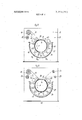
- FIGS. 2 and 3 essentially consists of an air-permeable pressure surface in the form of a cylinder 15, and airimpermeable pressure surface, which is constituted in the printing area by the dye-coated strip-like printing foil 1 1, devices 24 for heating the pressure surfaces l1, 15, (for example infrared radiators) swingably attached to attachment places 26, and a device for generating a vacuum in the interior of the air-permeable pressure surface 15.
- the device for generating the vacuum is not shown in the drawing.
- the device operates in the following manner:
- FIGS. 7-9 Additional advantageous features of this embodiment will immerge from the following description and the drawings contained in FIGS. 7-9.
Abstract
Disclosed herein is an improved system for printing on textile by sublimation of a dye-coating contained on a printing foil the printing occurring when the textile and the foil are placed in contact under the influence of heat and pressure.
Description
United States Patent [191 Kannegiesser et al.
APPARATUS FOR PRINTING ON TEXTILE STRIPS AND PIECES Inventors: Herbert Kannegiesser,
Hollwiesen-Vlotho; Richard Juraschek, Vloth, Weser am Kinderheim; Klaus Mussiger, Bad Salzuflen, all of Germany Assignee: Kannegiesser Machinentabrik Kommanditgesellschaft, Vlotho/Weser, Hollwiesen, Germany Filed: Feb. 2, 1971 Appl. No.: 111,966
Foreign Application Priority Data Feb. 5, 1970 Germany P 20 05 186.9
Feb. 27, 1970 Germany P 20 09 211.9 Dec. 11, 1970 Germany P 20 61 026.8 Dec. 14, 1970 Germany P 20 61 450.0
U.S. Cl. 68/5 D, 68/200, 68/13 R,
[51] Int. Cl. D06c 1/00 [58] Field of Search .1 118/257, 50, 641. 118/211; 68/200, 5 D, 13 R; 34/122, 123. 125; 8/25; 156/285. 286
[56] References Cited UNITED STATES PATENTS 1,965,257 7/1934 Poschel 8/25 2,174,744 10/1939 Hill 2,429,338 10/1947 Adams.... 2,820,131 l/1958 Kodama 118/642 X Primary Examiner-John P. Mcln'tosh Attorney-Sughrue, Rothwell, Mion, Zinn & Macpeak [57] ABSTRACT Disclosed herein is an improved system for printing on textile by sublimation of a dye-coating contained on a printing foil the printing occurring when the textile and the foil are placed in contact under the influence of heat and pressure.
10 Claims, 9 Drawing Figures PATENTEB 0m 30 1975 SHEET 10? 4 APPARATUS FOR PRINTING ON TEXTILE STRIPS AND PIECES BACKGROUND OF THE INVENTION 1. Field of the Invention This invention relates to apparatus for printing on textile strips and pieces, preferably those which are made of knit goods with synthetic fibers, by means of the sublimation of the dyestuff coating of printing foils, whereby the fabric to be treated is printed upon by the printing foils between pressure surfaces which partly rotate with each other, and which thus adjoin each other, or between such surfaces which can be moved toward each other, with simultaneous application of pressure and heat.
2. Description of the Prior Art It is known that textile strips and pieces can be printed on by means of dye-coated printing foils in calenders, presses and the like. In all of these cases, the textile strip or the textile piece, which is to be printed on, is placed, togetherwith the printing foil, between two working surfaces, which roll upon each other with relatively strong pressure, which rotate with each other, or which can be moved toward each other, at least one of which surfaces is heated. The resultant pressure and heat transmission produces a sublimation of the dyes on the printing foil, due to which these dyes are transferred to the textile strip or the textile piece.
In the case of textile strips and pieces which are made of knit goods with synthetic fibers, the high pressing pressure which is exerted during the printing process in the known methods and devices makes the knit pattern of these fabrics considerably worse. The reason for this deterioration is that the high pressure exerted during the printing process upon the textile strips and pieces, in combination with the very great heating of these strips and pieces, leads to a lasting deformation of the knitpattern. The distortion is lasting because the synthetic fibers in the goods must be heated up to the socalled start of plasticity and the pressure exerted in this area upon the fibers causes them to be permanently deformed. The deformation can be recognized by the fact that the thickness of the knit goods, after the printing process, is considerably smaller. For example, the side portion of a pullover sweater made of polyester fibers, before printing had a thickness of 1.1 mm and, after printing, had a thickness of 0.55 mm. The pressure employed was about 0.2 kglcm Further, the dyes from the printing foil cannot penetrate deeply enough into the knit goods which are compressed with heavy pressure and whose volume is reduced. As a result, when the knit goods are stretched, for example in a sweater, the basic color of the fibers used in making it becomes visible again. This impairs the quality.
The heavy pressure, which has a bad effect, is due to the design and construction in the known devices. In particular, it is due to the fact that either two rigid working surfaces which are flat only in a limited area, or one rigid and one flexible working surface are pressed together with mechanical pressure elements. For example, in the device described in German patent number 845,785, where two pressure surfaces, made up of one roller and a transport rotate with each other in a certain area, the pressure rises from kg/cm up to an adjusted maximum pressure and then drops again to 0 kg/cm in a pressure zone which includes about of the roller circumference. This high and varying pressure causes the printed fabric to reveal shadings.
SUMMARY OF THE INVENTION The present invention overcomes the disadvantages of the prior art noted above, and is characterized by the fact that the strips and pieces, on which a dye-coated printing foil has been placed, are put between an airpermeable pressure surface, which is connected to a vacuum device, and an air-impermeable flexible pres sure surface, which is heated directly or indirectly, in such a manner that the textile strips or pieces come to rest against the air-permeable pressure surface while the printing foil comes to rest against the airimpermeable pressure surface. Printing then takes place due to the action of the atmospheric overpressure generated by a vacuum device in the area of the pressure surfaces, while at the same time steam used for heating the textile strip or piece as well as the printing foil, is suctioned off through the air-permeable surface. Heating may also be accomplished by radiation, preferably infrared.
This invention makes it possible for the first time to print on textile strips and pieces, made of knit fabric with synthetic fibers, without any noteworthy deterioration in the knit pattern and with a depth effect that meets the requirements of every day practice. This can be achieved since the pressure, exerted upon the textile strips and pieces, is comparatively low and is equally distributed throughout the entire printing zone. This is also due to the suction drawing the dyes, which have been dissolved by the heat, into a knit fabric whose thickness is reduced only very little during the printing process. This is accomplished by virtue of the fact that the sublimation of the dyes, from the printing foil into the textile strip or the textile piece is intensified through the suction of the vacuum. The side portion of the sweater mentioned above, when printed according to the method of this invention, with a pressing pressure of about 0.06 kg/cm still has a thickness of 0.93 mm. after the printing process. The volume of the knit fabric has thus been reduced by only about 15 percent. In the known methods, the reduction was about 50 percent.
Another thing that is new and advantageous in this invention is a device for printing upon textile strips and pieces by means of dye-coated printing foils placed between pressure surfaces which partly rotate with each other and thus adjoin each other, using pressure and heat. One of the pressure surfaces is comprised of an air-impermeable, flexible, heat-resistant conveyer belt, while the other pressure surface is made up of a cylinder whose casing is air-permeable, whereby both of the pressure surfaces can be pressed upon each other in the area in which they rotate with each other, through atmospheric overpressure, generated by a vacuum device which is connected to the inside chamber of the cylinder.
This invention makes it possible to carry out the method mentioned in the beginning in an optimum fashion. Another advantage is that the device can be used both for printing of wide, long strips and for printing smaller pieces.
BRIEF DESCRIPTION OF THE DRAWINGS FIG. 1 is' a cross-sectional view of one embodiment of the invention.
FIG. 2 is a longitudinal cross section of another embodiment of the invention.
FIG. 3 shows the beginning of the printing area of the device illustrated in FIG. 1.
FIG. 4 is a longitudinal cross section of another embodiment of the invention.
FIG. 5 is a detail of FIG. 4.
FIG. 6 is another detail of FIG. 4.
FIG. 7 is a longitudinal cross section through the device with the beginning pieces of foil and textile inserted into the printing area.
FIG. 8 shows the device of FIG. 7 but with the foil and textile already inserted further into the printing area.
FIG. 9 shows the device of FIG. 7 during the continuous printing operation.
DETAILED DESCRIPTION OF THE PREFERRED EMBODIMENTS.
A device according to this invention is illustrated in FIG. 1. It essentially consists of an air-permeable pressure surface in the form of a cylinder 15, an airimpermeable pressure surface in the form of a flexible conveyer 16, a device in the form of heat radiator 24 for heating the pressure surfaces 15, 16, the textile strips 10 and pieces 12, located between them and a device for generating a vacuum inside the air-permeable pressure surface (cylinder). The device for generating the vacuum is not shown in the drawing.
The device for heating the pressure surfaces can also be provided in a different form. For example, high frequency energy can be used.
In case of heating by means of heat radiators 24, such as infrared radiators, it suffices, as illustrated in the drawing, to arrange heat radiators 24 on the side of the air-impermeable pressure surface which is designed as a conveyor belt 16. The radiation intensity of the heat radiators 24, can be regulated by changing the interval between the radiators and the pressure surface 16 and- /or by changing the electrical voltage and/or by using thermostats. It is also advantageous to arrange the individual heat generators 24 in each case, swingably on their attachment places 26. If necessary, however, heat radiators 24 or other heating elements can be arranged in the interior of cylinder 15.
The surface of the cylinder 15 is made of screen-like sheet metal with boreholes 14 which are close to each other, preferably a sheet metal with a thickness of 0.3-l0mm and boreholes with a diameter of 0.3-0.5mm. The use of such a sheet metal offers the advantage that, when printing on the textile strips 10 or textile piece 12, no markings will be left on these materials. It is also advantageous to make the screen-like sheet metal of aluminum or some other material that will reflect heat rays, and to place, over the cylindrical pressure surface 15, a coating made of heat-resistant fabric, for example the kind that is known under the brand name Nomex.
The conveyer belt 16 is made of a flexible, heatresistant material and it is driven and guided via drive and guide rollers 17.
The rotating pressure surfaces 15 (cylinder), 16 (conveyor belt) can be driven in the known manner. It is a good idea to drive only one pressure surface directly, and to have the other pressure surface taken along as result of friction connection between the surfaces.
The area of the cylindrical, air-permeable pressure surface 15, which does not cooperate with the conveyor-belt 16, is covered by a cover plate 18 made of airimpermeable material, and mounted preferably on the inside of cylinder 15.
Known devices for the positioning and guidance of the textile strips and of the pressure foil 11 are provided for the purpose of printing on the textile strips 10.
The following known devices are illustrated in the drawing in FIG. 1:
A shaft 20, with its pressure foil 11 which is rolled-up but not yet used;
A shaft 21, for rolling-up the printed textile strips 10;
A running incline 22 for the shaft 21;
A shaft 23, for rolling-up the used pressure foils.
For the purpose of printing textile pieces 12, especially, in order to be able to feed such goods into the device to begin with, a placement surface 27 is provided on the operating side of the device. This placement surface 27 exists because the conveyer belt 16, which serves as a pressure surface, is so far moved, from cylinder 15, at the location 27 that the textile piece 12, which is to be printed on, and the printing foils 13 can easily be placed upon and lined up on it. The conveyer belt 16 is supported by a table plate 25 in the area of the placement surface 27. Furthermore, a removal sheet 28 is provided for collecting the printed textile pieces 12. Printed pieces 12 can run on this removal sheet 28 with their pertinent pressure foils 13. The rotating pressure surfaces are driven in rhythm during the printing of pieces 12.
The device operates in the following manner:
The rolled-up textile strips 10, which are to be printed on, are placed on the rollers 19 which are arranged on the operating side of the device. The shaft 20 with the dye-coated printing foil 11 rolled-up upon it, is positioned on the device in a known manner. The beginning edge of the textile strip 10 and the edge of the printing foil 11 are drawn over the placement surface 27 and are introduced between the pressure surfaces 15 (cylinder), and 16 (conveyer belt). After leaving the area in which the pressure surfaces l5, l6 rotate with each other, the beginning edges of textile strip 10 and printing foil 11 are attached to the shaft 21, 23 which are in the upper area of the device. After this operation has been completed, we can begin printing on the tex-. tile strip 10. This operation is continual.
A further embodiment of this invention concerns a device for printing on textile strips, preferably those which are made of knit goods with synthetic fibers, by means of the sublimation of the dye layer of pressure foils, whereby the textile strips to be printed on can be printed upon, by the printing foils, between partly corotating and closely adjoining pressure surfaces, with the simultaneous application of pressure and heat,
whereby one pressure surface is air-impermeable, flexible,.and heat-resistant, while the other pressure surface is air-permeable and has the shape of a cylinder.
In this embodiment the printing foil is airimpermeable and flexible so that it simultaneously serves as a pressure surface in the printing area, an area in which the pressure surfaces rotate together and in which they can be pressed upon each other by means of atmospheric over pressure, generated through a vacuum device which is in contact with the inside chamber of the air-permeable pressure surface.
In a system in accordance with this embodiment the production and maintenance cost of thedevice are reduced. This is clearly seensince we can now eliminate the conveyor belt, including some of its guide rollers.
Additional advantageous features of the invention are described in detail below with the help of FIGS. 2 and 3. l
The embodiment illustrated in the drawings in FIGS. 2 and 3 essentially consists of an air-permeable pressure surface in the form of a cylinder 15, and airimpermeable pressure surface, which is constituted in the printing area by the dye-coated strip-like printing foil 1 1, devices 24 for heating the pressure surfaces l1, 15, (for example infrared radiators) swingably attached to attachment places 26, and a device for generating a vacuum in the interior of the air-permeable pressure surface 15. The device for generating the vacuum is not shown in the drawing.
The outside surface of the cylinder 15 is made of a screen-like sheet metal with bore holes 14. On the inside, in the area outside the printing area, it is covered by an air-impermeable cover plate 18.
For printing on the textile strips there is provided known devices for the positioning and guiding of the strips and printing foil 11. More specifically, there is provided rollers 19 for positioning of the rolled-up textile strips 10 which are to be printed on; shaft 20 with its rolled-up, as yet unused printing foil 11; shaft 21 for rolling up the printed textile strips 10; running incline 22 for the shaft 21; shaft 23 for rolling up used printing foils 11; running incline 29 for the shaft 23; guide rollers 31, 32 for the guidance of textile strips 10 and printing foils 11, whereby an introduction belt 30 is from time to time also guided around the guide roller 32.
For introducing the beginning of textile strips 10 and the printing foil 11 into the printing area, there is provided, at the end of the printing area, a shaft 36, with a heat-resistant, air-impermeable introduction belt 30 which can be rolled-up and off on this shaft. More specifically, the introduction belt 30, when the vacuum device is turned on and the air-permeable pressure surface runs backward in the direction of rotation indicated by arrow B, will roll off the shaft 36. When the rotation is forward, along arrow A, it is rolled-up on the shaft 36, whereby the part of the introduction belt 30 which is to be rolled off or rolled on, comes to rest against the air-permeable pressure surface 15 in the pressure area.
At the beginning of the printing area we have provided a scraper 33 which is intended to separate the beginning edge of the introduction belt 30 from the airpermeable pressure surface 15 and which is supposed to guide it on the table plate 25 of the placement surface 27. Furthermore, we have provided a guide roller 34 which has the purpose of pressing the introduction belt 30 and the beginning pieces of textile strip 10 and printing foil 11, which are manually placed upon that belt, during the insertion process, upon the placement surface 27, and at the same time to make sure that the beginning pieces will be picked up and taken along by the introduction belt 30. t
The scraper 33 and the guide roller 34 are preferably swingably positioned in a column bearing 35. The scraper 33 can be placed against the air-permeable pressure surface 15 and the guide roller 34 can be placed on the table plate 25 of the placement surface 27.
The portion of the printing area, in which the heat radiators 24 are arranged, is protect-ed against heat losses by known devices, such as insulation 37. The airpermeable pressure surface 15 is driven by known drive means.
The device operates in the following manner:
The rolled-up textile strip 10, which is to be printed on, isfirst placed on rollers 19 which are arranged on the operating side of the device and the shaft 20, while the dye-coated air-impermeable flexible foil 1 1, rolledup upon shaft, is positioned on the device in the known manner. Then the device is set in motion in such a manner that the air-permeable pressure surface 15, when the vacuum device is turned on, will run backward in the direction of arrow B, whereby the introduction belt 30, at the end of the printing area, is rolled off the shaft 36. This continues until the beginning piece of the introduction belt rests on the table plate 25 of the placement surface 27. After this has been done, the device is turned off and the beginning pieces of the printing foil 11 and of the textile strip 10 are placed upon the beginning piece of the introduction belt 30 which lies on table plate 25. If the device is now set in motion in such a manner that the air-permeable pressure surface 15 will run in the direction of arrow A when the vacuum device is on, then we not only roll up the introduction belt 30 but simultaneously also introduce the be ginning pieces of textile strip 10 and printing foil 11 into the printing area and even move them beyond that area.
After the beginning pieces of the textile strip 10 and printing foil 11 have left the printing area, the device is turned off again in order to wind the beginning pieces by hand upon shaft 21, 23, respectively, to attach them to the shaft. After this operation has been completed, we can begin the continuous printing of the textile strip 10.
It is also possible, in the manner described above, to introduce only the printing foil 11 into the printing area by means of the introduction belt 30, to introduce it into the printing area, to attach it to shaft 23, and then to insert the textile strip 10 into the printing area by means of printing foil 11.
The device can be equipped with all advantageous features contained in the invention described in the be ginning, to the extent that they are applicable to it.
The actual printing process takes place in the manner described earlier.
In another embodiment the device contains, at the beginning of the printing area, for the purpose of guiding the textile strip and the printing foil, a guide roller. As a result, the textile strip and the printing foil are moved toward the air-permeable cylindrical pressure surface in tangent fashion, at the beginning of the printing area. This feed operation, however, is disadvantageous because folds develop as a result of it in the tangent area in the textile strip and/or printing foil. The folds develop because the suction, prevailing in the tangent area, springing from the air-permeable cylindrical pressure surface, caused by the vacuum prevailing in the interior of the pressure surface, tries to pull the textile strip and/or the printing foil against the airpermeable, cylindrical pressure surface at the beginning of the printing area. The same applies to the end of the printing area, where, in case of a tangent-like evacuation of the textile strip and/or printing foil, the latter are not perfectly released by the vacuum.
In this embodiment the above problems are solved to the extent that the textile track and the printing foil will be able to run up on the air-permeable, cylindrical pressure surface without wrinkles and will leave that surface again without wrinkles.
The device includes, at the beginning and at the end of the printing area, a guide roller for the guidance of the textile strip and the pressure foil, which are so positioned that they constantly come to rest automatically against the air-permeable, preferably cushioned, cylindrical pressure surface, including the printing unit consisting of the textile strip and the printing foil.
This embodiment thus eliminates the disadvantageous tangent-like feeding and evacuation of the textile strip and printing foil to the air-permeable, cylindrical pressure surface, and, moreoever, it does this also when the air-permeable, cylindrical pressure surface is padded and when the thickness of the padding is changed, for example, during a longer period of printing.
It is also advantageous that it is possible particularly rapidly and perfectly to insert the beginning edge of a printing foil into the printing area by means of this embodiment.
Additional advantageous features of the embodiment will emerge from the following description.
The device shown in FIG. 4 for the purpose of printing on textile strip 10 by means of sublimation of the dye-coating of the pressure foil 11 essentially consists of an air-permeable, padded, cylindrical pressure surface 40, made up of a cylinder 15, whose outside surface has bore holes 14 and a padding 41, a guide roller 42 at the beginning and the guide roller 43 at the end of the printing area for the purpose of guiding the textile strip 10 and printing foil 11, and heat radiators 24 for heating the pressure surfaces. The printing foil 11 is at the same time the second pressure surface in the printing area.
The guide rollers 42, 43 are so positioned on the frame of the device that they will automatically, due to the action of a spring, rest against the air-permeable, cylindrical pressure 40, during the pressure process. The spring positioning of the guide rollers 42, 43 is not shown in the drawings.
The interior of the cylinder 15 is connected to a device, not shown in the drawings for the purpose of generating a vacuum. As a result the printing unit, made up of the textile strip 10 and the printing foil 11, in the printing area, rests against the air-permeable, padded, cylindrical pressure surface 40 under pressure.
For the purpose of printing on textile strip 10 we furthermore have provided known devices for the positioning and further guidance of the same as well as of the printing foil 11. These include rollers 19 for the positioning of the rolled-up textile tracks 10 which are to be printed on, shaft 20 with its rolled-up as yet unused pressure foil 11, shaft 21 for rolling up the printed-on textile strips 10 and shaft 23 for rolling up the used printing foil 11.
The device operates in the following manner:
Before the beginning of the pressure process, the beginning edge lla of the printing foil 11 is moved for a small distance by hand over the insertion slit 39 which is constituted, at the beginning of the printing area, by the round .portion of the guide roller 42 and the airpermeable, padded, cylindrical pressure surface 40. It is then placed upon the air-permeable, cylindrical pressure surface 40 which is standing still at that moment (FIG. 5). Because of the vacuum prevailing in the interior of the cylinder 15, the beginning piece 11b of the printing foil 11 is then drawn into the insertion slit 39. (FIG. 6). Then the beginning piece 10b, with the beginning edge 10a of the textile strip 10, which is to be printed on, is placed upon the printing foil 11 and the rotation drive of the cylinder 15 (not shown in the figures) is turned on. As a result the pressure surface 40 starts to rotate, picking up and taking along the printing unit consisting'of textile track 10 and printing foil 11, in the direction of arrow A. The actual printing process which follows is known. However, because of this invention it can be performed perfectly, without the formation of wrinkles on the printing foil 11 and/or the textile strip 10 because at the beginning and the end of the printing area, the guide rollers 42, 43, and the printing unit, come to rest against the air-permeable, padded, cylindrical pressure surface 40.
By means of the above-mentioned means for introducing the beginning piece 11b of the printing foil 11 into the printing area we can make such that it can be introduced not only quickly and perfectly but also without any aids such as introduction belts.
A further embodiment proposes additional improvements.
The heat radiation, coming from the heat radiators in the devices described above, is quite nicely suited for the printing of textile strips by means of the dye-coating of printing foils. But, at the beginning and at the end of the printing process, as well as in case of breakdowns in the device, this sort of heating is not desirable. At the beginning and end of a printing process, it is undesirable particularly because a piece of printing foil will then always run through the device without the textile strip and because, in this manner, the dye-coating is transferred to the covering, the winding, or the padding of the pressure surface. In case of trouble inside the device, heat radiation is undesirable because, when the rotation or circulation drive of the pressure surface fails, it can lead to burns on the printing unit consisting of the textile strip and the printing foil. If one of the pressure surfaces has a covering or a padding, then this may burn up also.
Because medium-wave heat radiators, also called infrared radiators, require a certain time from the moment they are turned on until they attain their standard output which of course applies also to the tum-off process the problem described above cannot be solved by turning the heat radiators on or off.
In this embodiment this above-mentioned device is improved to the extent that the heat radiation, coming from the heat radiators can enter the printing area only if it is needed for the printing process and furthermore, in case of trouble, the printing area can be immediately screened against the heat radiation coming from the heat radiators.
In this embodiment the heat raidation, coming from the heat radiators and aimed at the pressure surfaces, can be interrupted by a diaphragm which can be moved between the heat radiators and the printing surfaces. We can advantageously provide for the following: during the passage of the beginning pieces (or the end pieces) of the printing foil and of the textile strip, through the radiation area, the heat radiation can be interrupted.
By means of the diaphragm it is possible to protect the pressure surface and/or the printing foil lying between them and/or the textile strip with comparatively simple means which provide protection against unwanted heat radiation, and this is true both during each and every desired phase of the printing process as well as in case of trouble.
It is furthermore advantageous to attach the diaphragm looking in the direction in which the device works laterally on drive and guide means, which can be driven synchronously with the pressure surfaces, by means of endless chains. This in particular facilitates a comparatively simple and safe diaphragm drive.
Additional advantageous features of this embodiment will immerge from the following description and the drawings contained in FIGS. 7-9.
The device for printing textile strip 10, by means of the sublimation of the dye-coat on printing foil 1] essentially consists of a cylinder 15 as an air-permeable, first pressure surface, a guide roller 42 at the beginning and a guide roller 43 at the end of the printing area for the purpose of guiding the textile strip 10 and the printing foil 11, heat radiators 24 for the purpose of heating the pressure surfaces (preferably medium-wave infrared radiators) and an insulation 37 for the pressure area. The printing foil 11 can simultaneously be the second pressure surface in the printing area, as illustrated in the drawing in FIGS. 7-9.
The interior of cylinder 15, whose outside surface has boreholes 14, is connected to a device, not shown in the drawing for the purpose of generating a vacuum. As
a result of this the printing unit, made up of textile strip 10 and printing foil 11, in the printing area, will rest against the outside of the casing of cylinder 15 under pressure. The outside. of the casing of cylinder 15 can be provided with a covering or a padding (not shown).
The diaphragm 45 looking in the direction of operation of the device, is attached laterally to drive and guide means which can be driven synchronously with the pressure surfaces 1 l, 15 by endless chains 46. When there is no printing being done or in case of trouble the diaphragm stands between the air-permeable, first pressure surface (cylinder 15), and the front of the heat radiators 24. This is its basic position (see FIG. 7).
For printing on the textile strip 10 we have provided known devices for positioning and guiding of the same and the printing foil 11. More specifically, there is providedamong other things, rollers 19 for the positioning of the rolled-up textile tracks 10 which are to be printed on shaft 20 with its rolled-up, as yet not used printing foil 11, shaft 21 for rolling up printed textile tracks 10 and shaft 23 for rolling up used printing foils ll.
The device operates in the following manner:
As soon as the beginning piece 11b has been inserted 65 the insertion slit 39 of the printing area (FIG. 7), the diaphragm 45 is driven synchronously with he airpermeable, first pressure surface (cylinder 15) in the direction of rotation of the same (arrow A). In this way we can prevent, during the passage of the mutually staggered beginning pieces of 11b, 10b of printing foil 11 and textile strip 10, through the printing area, radiation heat from acting upon these pieces. In other words, it is impossible for the dye-coating of the beginning piece 11b of the printing foil 11, which is not covered by the textile track I0, to be transferred to the airpermeable, first pressure surface (cylinder 15) or upon a covering or padding which might be arranged upon the latter.
The size of the area of printing foil 11 and textile strip 10, which is to be screened by diaphragm 45, is adjustable. This area is preferably selected as large as it is illustrated in FIGS. 7 and 8. FIG. 8 also shows the further course of the insertion operation.
After the beginning pieces 11b, 11% of printing foil 11 and textile strip 10 have once again left the printing area, we stop the turning motion of the cylinder 15, the diaphragm 45 is returned to its basic position (FIG. 7), and the beginning pieces 11b, 10b are attached to the shaft 23, 21. The portion of printing unit, which is in the printing area at that time, consisting of a piece of printing foil 11 and a piece of textile strip 10, is thus protected against the effect of heat radiation during a printing pause.
After completion of the printing pause, the cylinder 15 and the diaphragm 45 are again driven together, whereby the diaphragm 45 however is moved only into the rear portion of the heat radiators 24 (FIG. 9.).
In case of trouble in the couse of printing, for example, in the feed area of pressure foil 11 and textile strip 10 and in case of the required stoppage of the cylinder 15, the diaphragm 45 is immediately moved into the basic position shown in FIG. 7. This is normally done automatically but it can also be done manually.
The end pieces of textile track 10 and pressure foil 1 1, not shown here, are likewise screened against radiation heat by diaphragm 45 during their passage through the pressure area.
Although the invention has been described with respect to the preferred embodiments thereof, it is understood by those skilled in the art that various modifications can be made in construction and arrangement within the scope of the invention as defined in the appended claims.
What is claimed is:
1. A system for printing on and dyeing textile material comprising a mesh material containing synthetic fibers, said system comprising:
a. printing foil means coated with a dye, said printing foil means being brought into contact with one side of said material;
b. first pressure means comprising an air impermeable, flexible heat resistant surface for maintaining at least an atmospheric pressure on said printingfoil means;
c. second pressure means comprising a cylindrical surface having an air permeable surface for maintaining a reduced pressure wherein said printing foil means with said material in contact therewith are positioned between said first and second pressure means such that the other side of said material is in contact with said second pressure means and wherein said second pressure means reduces the pressure to the extent that said printing foil means is held against said one side of said material without substantially changing the thickness of said material; and
d. heater means for heating said printing foil means and said material such that the dye on said printing foil means is released therefrom wherein said dye is drawn into said material due to the pressure differential between said first and second pressure means whereby said material is dyed in accordance with the dye on said printing foil means.
2. The system as set forth in claim 1 wherein said first pressure means is a conveyor belt.
3. The system as set forth in claim 1 wherein said heater means are infra-red heaters.
4. The system as set forth in claim 3 wherein said heater means includes means for varying the intensity of the heat applied to said printing foil means and said material.
5. The system asset forth in claim 1 wherein said second pressure surface means includes a heat resistant fabric covering said cylindrical surface.
6. A system for printing on and dyeing textile materials comprising a mesh material containing synthetic fibers said system comprising:
a. printing foil means comprising a flexible air impermeable surface for maintaining at least an atmospheric pressure on said one side of said material, said printing foil means coated with a dye, said dye being in contact with one side of said material;
b. pressure means comprising a cylindrical surface having an air permeable surface for maintaining a reduced pressure on the other side of said material wherein said material is positioned between said printing foil means and said pressure means such that the other side of said material is in contact with said pressure means and wherein said pressure means reduces the pressure to the extent that said printing foil means is held against said one side of said material without substantially changing the thickness of said material; and
c. heater means for heating said printing foil means and said material such that the dye on said printing foil means is released therefrom, wherein said dye is drawn into said material due to the pressure differential between the printing foil means and the pressure means, whereby said material is dyed in accordance with the dye on said printing foil means.
7. The system as set forth in claim 6 further including guide roller means positioned to contact said cylindrical surface, for guiding said material and said printing foil means.
8. The system as set forth in claim 6 wherein said heater means includes a heat radiating means and a diaphragm means for movement between said heat radiating means and printing foil means wherein the heat applied to said printing foil means and said material is interrupted.
9. The system as set forth in claim 8 wherein the heat is interrupted during the movement of the initial and end portions of said printing foil means and material means along said pressure means.
10. The system as set forth in claim 9 wherein said diaphragm means includes drive means and guide means and wherein said diaphragm means is driven in synchronism with said pressure means.
Claims (10)
1. A system for printing on and dyeing textile material comprising a mesh material containing synthetic fibers, said system comprising: a. printing foil means coated with a dye, said printing foil means being brought into contact with one side of said material; b. first pressure means comprising an air impermeable, flexible heat resistant surface for maintaining at least an atmospheric pressure on said printing foil means; c. second pressure means comprising a cylindrical surface having an air permeable surface for maintaining a reduced pressure wherein said printing foil means with said material in contact therewith are positioned between said first and second pressure means such that the other side of said material is in contact with said second pressure means and wherein said second pressure means reduces the pressure to the extent that said printing foil means is held against said one side of said material without substantially changing the thickness of said material; and d. heater means for heating said printing foil means and said material such that the dye on said printing foil means is released therefrom wherein said dye is drawn into said material due to the pressure differential between said first and second pressure means whereby said material is dyed in accordance with the dye on said printing foil means.
2. The system as set forth in claim 1 wherein said first pressure means is a conveyor belt.
3. The system as set forth in claim 1 wherein said heater means are infra-red heaters.
4. The system as set forth in claim 3 wherein said heater means includes means for varying the intensity of the heat applied to said printing foil means and said material.
5. The system as set forth in claim 1 wherein said second pressure surface means includes a heat resistant fabric covering said cylindrical surface.
6. A system for printing on and dyeing textile materials comprising a mesh material containing synthetic fibers said system comprising: a. printing foil means comprising a flexible air impermeable surface for maintaining at least an atmospheric pressure on said one side of said material, said printing foil means coated with a dye, said dye being in contact with one side of said material; b. pressure means comprising a cylindrical surface having an air permeable surface for maintaining a reduced pressure on the other side of said material wherein said material is positioned between said printing foil means and said pressure means such that the other side of said material is in contact with said pressure means and wherein said pressure means reduces the pressure to the extent that said printing foil means is held against said one side of said material without substantially changing the thickness of said material; and c. heater means for heating said printing foil means and said material such that the dye on said printing foil means is released therefrom, wherein said dye is drawn into said material due to the pressure differential between the printing foil means and the pressure means, whereby said material is dyed in accordance with the dye on said printing foil means.
7. The system as set forth in claim 6 further including guide roller means positioned to contact said cylindrical surface, for guiding said material and said printing foil means.
8. The system as set forth in claim 6 wherein said heater means includes a heat radiating means and a diaphragm means for movement between said heat radiating means and printing foil means wherein the heat applied to said printing foil means and said material is interrupted.
9. The system as set forth in claim 8 wherein the heat is interrupted during the movement of the initial and end portions of said printing foil means and material means along said pressure means.
10. The system as set forth in claim 9 wherein said diaphragm means includes drive means and guide means and wherein said diaphragm means is driven in synchronism with said pressure means.
Applications Claiming Priority (4)
| Application Number | Priority Date | Filing Date | Title |
|---|---|---|---|
| DE19702005186 DE2005186A1 (en) | 1970-02-05 | 1970-02-05 | Foil printing for knitted goods |
| DE19702009211 DE2009211C3 (en) | 1970-02-27 | 1970-02-27 | Device for printing textile webs |
| DE19702061026 DE2061026B2 (en) | 1970-12-11 | 1970-12-11 | Device for printing textile webs |
| DE19702061450 DE2061450C3 (en) | 1970-12-14 | 1970-12-14 | Device for printing textile webs |
Publications (1)
| Publication Number | Publication Date |
|---|---|
| US3768280A true US3768280A (en) | 1973-10-30 |
Family
ID=27431017
Family Applications (1)
| Application Number | Title | Priority Date | Filing Date |
|---|---|---|---|
| US00111966A Expired - Lifetime US3768280A (en) | 1970-02-05 | 1971-02-02 | Apparatus for printing on textile strips and pieces |
Country Status (3)
| Country | Link |
|---|---|
| US (1) | US3768280A (en) |
| FR (1) | FR2079256B1 (en) |
| GB (1) | GB1312529A (en) |
Cited By (26)
| Publication number | Priority date | Publication date | Assignee | Title |
|---|---|---|---|---|
| US3848435A (en) * | 1973-07-23 | 1974-11-19 | Alamance Ind Inc | Transfer printing machine |
| US3874846A (en) * | 1973-06-20 | 1975-04-01 | John M Ashe | Transfer printing method |
| US3880579A (en) * | 1972-03-17 | 1975-04-29 | P Lamaire & Cie Sa Ets | Thermo-printing process |
| US3896762A (en) * | 1973-12-07 | 1975-07-29 | Purdue Research Foundation | Coating apparatus |
| US3949574A (en) * | 1973-07-20 | 1976-04-13 | Richard Donovan Glover | Sublimatic printing machine |
| US4007003A (en) * | 1975-09-12 | 1977-02-08 | Armstrong Cork Company | Product and method of printing carpet with a transfer paper- II |
| US4049374A (en) * | 1975-07-21 | 1977-09-20 | Thomas Rejto | Simultaneous transfer printing and embossing or surface texturing method |
| US4057864A (en) * | 1974-07-09 | 1977-11-15 | Tootal Limited | Wet transfer printing process and apparatus |
| US4072462A (en) * | 1973-11-12 | 1978-02-07 | L. B. Holliday & Company Limited | Transfer printing |
| US4089193A (en) * | 1973-06-25 | 1978-05-16 | Mitter & Co. | Machine for printing on textile webs |
| US4116022A (en) * | 1975-09-01 | 1978-09-26 | Kleinewefers Industrie-Companie Gmbh | Device for printing on webs of textile material |
| US4128395A (en) * | 1972-12-15 | 1978-12-05 | Imperial Chemical Industries Limited | Transfer printing with carboxylic dyes |
| US4178782A (en) * | 1976-08-25 | 1979-12-18 | Kleinewefers Gesellschaft mit beschrankter Haftung | Device for printing by sublimation |
| US4195499A (en) * | 1978-03-22 | 1980-04-01 | Yost John A | Transfer printing apparatus |
| US4199317A (en) * | 1973-12-13 | 1980-04-22 | Sublistatic Holding Sa | Printing process |
| US4242092A (en) * | 1970-11-12 | 1980-12-30 | Glover Richard D | Method of sublimatic printing on sheet structures |
| US4442560A (en) * | 1979-10-01 | 1984-04-17 | A. Monforts | Method for continuously finishing and/or dyeing planar textile structures |
| US4523402A (en) * | 1981-11-09 | 1985-06-18 | Dobson Charles Edward | Sign construction |
| US4670084A (en) * | 1983-06-20 | 1987-06-02 | David Durand | Apparatus for applying a dye image to a member |
| US4671205A (en) * | 1981-07-21 | 1987-06-09 | Billeter Kunstsoffpulver A.G. | Apparatus for applying partial surface coatings |
| US5989380A (en) * | 1997-01-08 | 1999-11-23 | Frischer; Paul | Process of dry printing a paper-like non-woven wall covering material |
| US6425926B1 (en) * | 1999-05-04 | 2002-07-30 | Jakobus Hindriks | Thermosol treatment of textiles carrying a dye |
| WO2004007202A1 (en) | 2002-07-12 | 2004-01-22 | Xiangyang Lu | The apparatus for paperless transfer printing and the process thereof |
| US20100212059A1 (en) * | 2009-02-24 | 2010-08-26 | Lee Peter Morrison | Methods and garments for dye sublimation |
| US20170144431A1 (en) * | 2015-11-23 | 2017-05-25 | Kyungil-Tech Co., Ltd. | Hybrid transfer machine |
| US11660854B2 (en) | 2021-07-30 | 2023-05-30 | Duksung Co., Ltd | Continuous sublimation transfer method using a vacuum suction roller |
Families Citing this family (2)
| Publication number | Priority date | Publication date | Assignee | Title |
|---|---|---|---|---|
| CN113561638B (en) * | 2021-07-06 | 2023-01-03 | 河南今明纸业有限公司 | Paper gilding device is adorned in connecing of steel band welt |
| KR102369765B1 (en) * | 2021-07-30 | 2022-03-03 | 주식회사 덕성 | Continuous printing apparatus and method using vacuum suction roller |
Citations (4)
| Publication number | Priority date | Publication date | Assignee | Title |
|---|---|---|---|---|
| US1965257A (en) * | 1932-08-25 | 1934-07-03 | Decorative Dev Inc | Method of and apparatus for printing and dyeing |
| US2174744A (en) * | 1937-02-03 | 1939-10-03 | Harold S Hill | Apparatus for pressing a moving web in paper making machines |
| US2429338A (en) * | 1945-04-02 | 1947-10-21 | Los Angeles Paper Box Factory | Drum drier for web with radiant heater |
| US2820131A (en) * | 1951-08-01 | 1958-01-14 | Sprague Electric Co | Curing oven |
-
1971
- 1971-02-02 US US00111966A patent/US3768280A/en not_active Expired - Lifetime
- 1971-02-03 FR FR7103608A patent/FR2079256B1/fr not_active Expired
- 1971-04-19 GB GB2118071A patent/GB1312529A/en not_active Expired
Patent Citations (4)
| Publication number | Priority date | Publication date | Assignee | Title |
|---|---|---|---|---|
| US1965257A (en) * | 1932-08-25 | 1934-07-03 | Decorative Dev Inc | Method of and apparatus for printing and dyeing |
| US2174744A (en) * | 1937-02-03 | 1939-10-03 | Harold S Hill | Apparatus for pressing a moving web in paper making machines |
| US2429338A (en) * | 1945-04-02 | 1947-10-21 | Los Angeles Paper Box Factory | Drum drier for web with radiant heater |
| US2820131A (en) * | 1951-08-01 | 1958-01-14 | Sprague Electric Co | Curing oven |
Cited By (31)
| Publication number | Priority date | Publication date | Assignee | Title |
|---|---|---|---|---|
| US4242092A (en) * | 1970-11-12 | 1980-12-30 | Glover Richard D | Method of sublimatic printing on sheet structures |
| US3880579A (en) * | 1972-03-17 | 1975-04-29 | P Lamaire & Cie Sa Ets | Thermo-printing process |
| US4128395A (en) * | 1972-12-15 | 1978-12-05 | Imperial Chemical Industries Limited | Transfer printing with carboxylic dyes |
| US3874846A (en) * | 1973-06-20 | 1975-04-01 | John M Ashe | Transfer printing method |
| US4089193A (en) * | 1973-06-25 | 1978-05-16 | Mitter & Co. | Machine for printing on textile webs |
| US3949574A (en) * | 1973-07-20 | 1976-04-13 | Richard Donovan Glover | Sublimatic printing machine |
| US3848435A (en) * | 1973-07-23 | 1974-11-19 | Alamance Ind Inc | Transfer printing machine |
| US4072462A (en) * | 1973-11-12 | 1978-02-07 | L. B. Holliday & Company Limited | Transfer printing |
| US3896762A (en) * | 1973-12-07 | 1975-07-29 | Purdue Research Foundation | Coating apparatus |
| US4199317A (en) * | 1973-12-13 | 1980-04-22 | Sublistatic Holding Sa | Printing process |
| US4057864A (en) * | 1974-07-09 | 1977-11-15 | Tootal Limited | Wet transfer printing process and apparatus |
| US4049374A (en) * | 1975-07-21 | 1977-09-20 | Thomas Rejto | Simultaneous transfer printing and embossing or surface texturing method |
| US4116022A (en) * | 1975-09-01 | 1978-09-26 | Kleinewefers Industrie-Companie Gmbh | Device for printing on webs of textile material |
| US4007003A (en) * | 1975-09-12 | 1977-02-08 | Armstrong Cork Company | Product and method of printing carpet with a transfer paper- II |
| US4178782A (en) * | 1976-08-25 | 1979-12-18 | Kleinewefers Gesellschaft mit beschrankter Haftung | Device for printing by sublimation |
| US4195499A (en) * | 1978-03-22 | 1980-04-01 | Yost John A | Transfer printing apparatus |
| US4442560A (en) * | 1979-10-01 | 1984-04-17 | A. Monforts | Method for continuously finishing and/or dyeing planar textile structures |
| US4671205A (en) * | 1981-07-21 | 1987-06-09 | Billeter Kunstsoffpulver A.G. | Apparatus for applying partial surface coatings |
| US5053254A (en) * | 1981-07-21 | 1991-10-01 | Armin Billeter | Process for applying partial coatings |
| US4523402A (en) * | 1981-11-09 | 1985-06-18 | Dobson Charles Edward | Sign construction |
| US4670084A (en) * | 1983-06-20 | 1987-06-02 | David Durand | Apparatus for applying a dye image to a member |
| US5989380A (en) * | 1997-01-08 | 1999-11-23 | Frischer; Paul | Process of dry printing a paper-like non-woven wall covering material |
| US6425926B1 (en) * | 1999-05-04 | 2002-07-30 | Jakobus Hindriks | Thermosol treatment of textiles carrying a dye |
| WO2004007202A1 (en) | 2002-07-12 | 2004-01-22 | Xiangyang Lu | The apparatus for paperless transfer printing and the process thereof |
| EP1541348A1 (en) * | 2002-07-12 | 2005-06-15 | Xiangyang Lu | The apparatus for paperless transfer printing and the process thereof |
| JP2005532925A (en) * | 2002-07-12 | 2005-11-04 | 盧向陽 | Printing apparatus and printing method that do not require paper |
| EP1541348A4 (en) * | 2002-07-12 | 2009-02-25 | Xiangyang Lu | The apparatus for paperless transfer printing and the process thereof |
| US20100212059A1 (en) * | 2009-02-24 | 2010-08-26 | Lee Peter Morrison | Methods and garments for dye sublimation |
| US20170144431A1 (en) * | 2015-11-23 | 2017-05-25 | Kyungil-Tech Co., Ltd. | Hybrid transfer machine |
| US9776390B2 (en) * | 2015-11-23 | 2017-10-03 | Kyungil-Tech Co., Ltd. | Hybrid transfer machine |
| US11660854B2 (en) | 2021-07-30 | 2023-05-30 | Duksung Co., Ltd | Continuous sublimation transfer method using a vacuum suction roller |
Also Published As
| Publication number | Publication date |
|---|---|
| FR2079256B1 (en) | 1976-09-03 |
| GB1312529A (en) | 1973-04-04 |
| FR2079256A1 (en) | 1971-11-12 |
Similar Documents
| Publication | Publication Date | Title |
|---|---|---|
| US3768280A (en) | Apparatus for printing on textile strips and pieces | |
| US6161304A (en) | Dryer assembly | |
| GB2314043A (en) | Heated inkjet print media support system | |
| US5160505A (en) | Method and apparatus for transfer printing of synthetic fabrics | |
| US4117699A (en) | Calenders for the thermal treatment of laminar material | |
| US3620881A (en) | Apparatus for printing both sides of single or multiple layer textile articles | |
| KR101425945B1 (en) | Pulse heating methods and apparatus for printing and dyeing | |
| US2594290A (en) | Apparatus for applying designs to plastic sheetlike materials | |
| US2217133A (en) | Machine for the multicolor printing of textile fabrics | |
| US3848435A (en) | Transfer printing machine | |
| CN110494288A (en) | Mostly band and multizone drying textile device | |
| US6637333B2 (en) | Apparatus to aid in fixing dye to fabric | |
| JPS5837434B2 (en) | Apparatus for curing sheet fabric by coating it with plastic | |
| US2174215A (en) | Decatizing fabrics | |
| US3699885A (en) | Screen printing machine with transport band for temporarily adhesively securing web during printing | |
| CN111908201B (en) | Printing equipment for textile fabric and working method thereof | |
| US3345756A (en) | Method and apparatus for drying a wet web | |
| GB1406584A (en) | Machine for finishing textile fabric | |
| GB1344301A (en) | Apparatus for continuous heat treatment of a web of sheet material | |
| US2030304A (en) | Printing | |
| GB1518905A (en) | Method of and apparatus for continuous decatising fabric | |
| US3446142A (en) | Drying device for a printing press | |
| US4899410A (en) | Continuous fabric treatment process | |
| GB1400968A (en) | Fabric finishing | |
| JPH0330496B2 (en) |