US3772645A - Vehicle alarm system - Google Patents
Vehicle alarm system Download PDFInfo
- Publication number
- US3772645A US3772645A US00219229A US3772645DA US3772645A US 3772645 A US3772645 A US 3772645A US 00219229 A US00219229 A US 00219229A US 3772645D A US3772645D A US 3772645DA US 3772645 A US3772645 A US 3772645A
- Authority
- US
- United States
- Prior art keywords
- alarm
- audio signal
- motion switch
- switch
- container
- Prior art date
- Legal status (The legal status is an assumption and is not a legal conclusion. Google has not performed a legal analysis and makes no representation as to the accuracy of the status listed.)
- Expired - Lifetime
Links
Images

Classifications
-
- E—FIXED CONSTRUCTIONS
- E05—LOCKS; KEYS; WINDOW OR DOOR FITTINGS; SAFES
- E05B—LOCKS; ACCESSORIES THEREFOR; HANDCUFFS
- E05B45/00—Alarm locks
- E05B45/005—Chain-locks, cable-locks or padlocks with alarms
-
- B—PERFORMING OPERATIONS; TRANSPORTING
- B62—LAND VEHICLES FOR TRAVELLING OTHERWISE THAN ON RAILS
- B62H—CYCLE STANDS; SUPPORTS OR HOLDERS FOR PARKING OR STORING CYCLES; APPLIANCES PREVENTING OR INDICATING UNAUTHORIZED USE OR THEFT OF CYCLES; LOCKS INTEGRAL WITH CYCLES; DEVICES FOR LEARNING TO RIDE CYCLES
- B62H5/00—Appliances preventing or indicating unauthorised use or theft of cycles; Locks integral with cycles
- B62H5/003—Appliances preventing or indicating unauthorised use or theft of cycles; Locks integral with cycles using chains or cables
-
- B—PERFORMING OPERATIONS; TRANSPORTING
- B62—LAND VEHICLES FOR TRAVELLING OTHERWISE THAN ON RAILS
- B62H—CYCLE STANDS; SUPPORTS OR HOLDERS FOR PARKING OR STORING CYCLES; APPLIANCES PREVENTING OR INDICATING UNAUTHORIZED USE OR THEFT OF CYCLES; LOCKS INTEGRAL WITH CYCLES; DEVICES FOR LEARNING TO RIDE CYCLES
- B62H5/00—Appliances preventing or indicating unauthorised use or theft of cycles; Locks integral with cycles
- B62H5/20—Appliances preventing or indicating unauthorised use or theft of cycles; Locks integral with cycles indicating unauthorised use, e.g. acting on signalling devices
-
- Y—GENERAL TAGGING OF NEW TECHNOLOGICAL DEVELOPMENTS; GENERAL TAGGING OF CROSS-SECTIONAL TECHNOLOGIES SPANNING OVER SEVERAL SECTIONS OF THE IPC; TECHNICAL SUBJECTS COVERED BY FORMER USPC CROSS-REFERENCE ART COLLECTIONS [XRACs] AND DIGESTS
- Y10—TECHNICAL SUBJECTS COVERED BY FORMER USPC
- Y10T—TECHNICAL SUBJECTS COVERED BY FORMER US CLASSIFICATION
- Y10T70/00—Locks
- Y10T70/40—Portable
- Y10T70/402—Fetters
- Y10T70/409—Shackles
-
- Y—GENERAL TAGGING OF NEW TECHNOLOGICAL DEVELOPMENTS; GENERAL TAGGING OF CROSS-SECTIONAL TECHNOLOGIES SPANNING OVER SEVERAL SECTIONS OF THE IPC; TECHNICAL SUBJECTS COVERED BY FORMER USPC CROSS-REFERENCE ART COLLECTIONS [XRACs] AND DIGESTS
- Y10—TECHNICAL SUBJECTS COVERED BY FORMER USPC
- Y10T—TECHNICAL SUBJECTS COVERED BY FORMER US CLASSIFICATION
- Y10T70/00—Locks
- Y10T70/40—Portable
- Y10T70/413—Padlocks
- Y10T70/487—Parts, accessories, attachments and adjuncts
- Y10T70/491—Shackles
-
- Y—GENERAL TAGGING OF NEW TECHNOLOGICAL DEVELOPMENTS; GENERAL TAGGING OF CROSS-SECTIONAL TECHNOLOGIES SPANNING OVER SEVERAL SECTIONS OF THE IPC; TECHNICAL SUBJECTS COVERED BY FORMER USPC CROSS-REFERENCE ART COLLECTIONS [XRACs] AND DIGESTS
- Y10—TECHNICAL SUBJECTS COVERED BY FORMER USPC
- Y10T—TECHNICAL SUBJECTS COVERED BY FORMER US CLASSIFICATION
- Y10T70/00—Locks
- Y10T70/50—Special application
- Y10T70/5009—For portable articles
-
- Y—GENERAL TAGGING OF NEW TECHNOLOGICAL DEVELOPMENTS; GENERAL TAGGING OF CROSS-SECTIONAL TECHNOLOGIES SPANNING OVER SEVERAL SECTIONS OF THE IPC; TECHNICAL SUBJECTS COVERED BY FORMER USPC CROSS-REFERENCE ART COLLECTIONS [XRACs] AND DIGESTS
- Y10—TECHNICAL SUBJECTS COVERED BY FORMER USPC
- Y10T—TECHNICAL SUBJECTS COVERED BY FORMER US CLASSIFICATION
- Y10T70/00—Locks
- Y10T70/50—Special application
- Y10T70/5872—For cycles
- Y10T70/5876—Anchors
Definitions
- ABSTRACT An alarm system for detecting movement of an object to which the alarm is attached when the object or the alarm is moved, having a power source which can be a battery, an audio signal means, a detection circuit and a gimbled trip or motion switch.
- the alarm system can be mounted on a device to be protected from theft and have an electrically conductive chain attached thereto which is connected into the detection circuit so that when the chain is broken the audio signal means will function.
- the gimbled motion switch is positioned and connected to the detection circuit so that if it is moved, it will cause the detection circuit to function creating an alarm in the form of an audio signal.
- the entire system can be mounted in a closed locked box which is attached to a valuable object which is to be protected such as a bicycle, business machine or storage box.
- the Prior Art relating to theft alarm actuation generally incorporates the principle of breaking or creating a circuit in which an alarm is positioned. Specifically, alarm circuits often incorporate a wire within a window, a lock, or other suitable electrical coupling means. Also, alarms are oftentimes tripped by intrusion into an electro-magnetic field, a field of sound waves, or a field of light waves.
- the foregoing alarm systems are most often placed in a stationary position.
- the alarm is built into the structure surrounding the door and is caused to operate upon prying of the door or the door lock.
- an alarm is used for a window, it is often placed within a circuit which is formed of a wire within the window.
- the wire is broken by reason of the window being broken, the circuit is broken causing an alarm to issue.
- light sources and electromagnetic sources it is usually necessary that an object break the close of the field.
- the alarms are basically static alarms which do not issue any alarm signal except in a given location. In other words, the building or vehicle must be broken into, or a fixed element thereof has to be moved.
- the prior art does not provide for an alarm utilized as a system to detect movement with respect to a relatively protable and valuable object.
- This invention enables an alarm to be issued from a portable object when the object is moved in an unwarranted manner, to help prevent the theft thereof.
- the alarm can be specifically utilized with not only bicycles, but office equipment, valuable containers such as strong boxes, and other devices such as luggage and baggage.
- the prior art specifically relating to light weight vehicles such as motorcycles and bicycles does not incorporate adequate alarms for warning when an unwarranted movement of the bicycles or motorcycles take place.
- the only way of preventing the theft thereof is to chain them, lock them, or cut the ignition as in the case of motorcycles.
- the entire bike or motorcycle can be lifted onto a larger vehicle for purposes of removal and theft.
- a lock or chain can be cut without any knowledge of those nearby.
- This particular device overcomes those deficiencies of the prior art by issuing an alarm when the motorcycle or a bicycle is removed or disturbed from the position in which it was originally placed.
- this invention overcomes the deficiencies of the prior art by creating an audio alarm system for protecting bicycles, motorcycles and all forms of portable and valuable equipment.
- This invention comprises a portable alarm system affixed or attached to a valuable piece of equipment to provide an audio warning when such equipment is tampered with.
- this invention comprises a first embodiment having a built in power supply such as a battery to operate the audio alarm thereof, for attachment to a bicycle or motorcycle.
- the audio alarm is set by a control switch and caused to function by a gimbled motion switch.
- the gimbled motion switch is implaced within the detection circuit to operate the audio signal means so that when the initial orientation of the gimbled motion switch is affected, it will cause the detection circuit to be completed to operate the audio alarm.
- a lock is provided with a casing for the entire device to provide access thereto for setting the gimbled motion switch in an initial location.
- a conductive chain is also linked to the device so that if it is cut or damaged, it will cause the detection circuit to create an audio alarm as when the gimbled trip or motion switch completes the circuit.
- Another embodiment incorporates an alarm type box which can be attached to or connected with a piece of portable equipment such as a typewriter, dictating machine, copying machine, or strongbox.
- a piece of portable equipment such as a typewriter, dictating machine, copying machine, or strongbox.
- the operation of the audio alarm is similar to the foregoing system.
- the chain can possible be eliminated so as to only incorporate a gimbled motion switch.
- an alarm will sound.
- a trickle charger can be utilized to charge the static power supply or battery of the invention.
- FIG. 5 shows a bottom view of the invention along line 55 of FIG. 4;
- FIG. 10 shows a schematic electrical form of an embodiment of this invention.
- FIG. 11 is an edge view of this invention along line 1l11 of FIG. 2.
- the alarm system 20 for use with a bicycle or motorcycle is shown attached to a bicycle 12 by connection to and around a vertical post 14 of the bicycle.
- the vertical post 14 is usually a part of most bicycles for purposes of providing general rigidity to the frame of the bicycle.
- Extending from the alarm system is a chain 16 which is wrapped around a post 18.
- a protuberance formed as a lock dial holder 20 is shown.
- the lock dial holder 20 is for purposes of operating a combination lock 22.
- the lock dial holder 20 has three dials 21, 23, and therein for suitable rotation and operation of the lock 22.
- the hinge 28 extends along a substantial length of the box 24.
- the hinge 28 can be affixed to the box in a suitable manner such as by rivets 40 which are shown holding the hinge to the box.
- the motion switch 64 is provided with a dielectric support 76 in the general shape of an inverted L.
- the dielectric support 76 is curved and can be made of a plastic material and molded to receive a support pin 78 having a ball 80 attached to the end thereof.
- the ball 80 seats within the socket seats 73 and which suitably clamp and accommodate the ball by means of pressure exerted from the arms 69 and 71 of a motion switch retention means 68.
- the dielectric support 76 has a pair of eyelets 82 and 84 which are seated and can be molded within the dielectric material 76.
- the eyelets have contact washers 86 and 88 respectively associated with each eyelet.
- the contact washers in trun are connected to soldering points or lugs 90 and 92 from which the wires detailed in the schematic electrical views are connected and through which an electrical circuit can be completed.
- the eyelets 82 and 84 serve to connect a hanging contact 94 which is looped through eyelet 82 by a bend 96 and projects upwardly through eyelet 84 with an upward extension 98.
- the motion switch 64 can be oriented so that when the upward projection 98 is out of contact with the eyelet 84, there will be no contact between the electrical connections 92 and 90.
- the upward projection 98 makes contact against the loop 84 and completes an electrical circuit from contacts 92 to 90.
- the motion switch 64 is connected through a double pole double throw switch 102 which has an operating tab 104.
- the double pole double throw switch is shown schematically in FIG. 8 and operates the circuit by means of being connected to the motion switch by wires 106 and to the remainder of the circuit for operation thereof.
- a locking cable or chain 16 which was shown in FIG. 1 is comprised of a cable section 108 and an end cap portion 110 which is seated within the box 24 within a rounded opening or an identation motion
- the end cap 110 can be riveted by rivets 114 which secure the end cap 110 into the base of the box 44.
- the cable 108 terminates in a seating cap 116 which is seated within an indentation or rounded opening 118 of the base 44 of the box 24.
- the seating cap 116 is of a rounded disc shaped design having a groove 120 circumferentially surrounding the upper portion of the cap 122 so that the groove 120 can be seated against the rounded interior surface of the circumferential opening 118.
- seating cap 116 is slid into the base 44 of the box 24 so.
- the chain 108 is comprised of a vinyl or other suitable outer cover 124 and has steel flexible tubing 126, interiorly located thereof.
- the steel tubing 126 is such that it provides a certain degree of armor or protection against one attempting to cut the chain 16.
- Interiorly of the flexible steel tubing 126 is a protective tubular layer 128 surrounding a series of electrical wires 130 each comprising an insulated wire 132 having a conductor 134 therein.
- the wires are specifically part of the operative features of the detection circuit of this invention, and will be described in greater detail with respect to the schematic views of FIGS. 7 through 10.
- the cable 108 is basically a locking cable to prevent physical removal of a bicycle or object to be protected, as well as warning when the cable is cut, broken or crimped badly.
- FIG. 8 a schematic view is shown wherein a power source or EMF is provided.
- the EMF is that of the battery 50.
- the battery is connected to a junction point 144 of the switch 102 so that the switch 102 can cause conduction of current through the remainder of the circuit.
- the switching tab 104 and switch 102 are connected and configured so that the switch effectively causes contact of the poles in a double pole double throw relationship.
- switch 102 has poles and contacts which go from a reset position R to a motion position M as indicated by the arrow.
- a set of contacts 140, 142, 144 and 146 allow a break and make situation to reset a relay that will be more fully described.
- the motiron switch 64 is shown schematically having a rounded configuration or circle which is analagous to the eyelet 84.
- the interior contact point is analagous to the arm 94.
- the switch can be connected and operate such that it makes contact from arm 94 to eyelet 82 which are represented by the outer circle 65 of the schematic configuration of the motion switch 64.
- the audio warning device 62 is basically a buzzer that can function mechanically or electrically to provide a certain tone when it is actuated.
- a relay switch 148 is shown having a coil 150 and a switch arm 152. The relay switch is shown across a set of junction points or terminals which are placed across the wires 130 of the cable 108.
- the motion switch 64 is connected by the reset position R and between terminals 144 and 156.
- the chain 108 is also connected to terminal 156.
- the relay 148 can be a reed switch of a single pole configuration which is activated by the source of EMF.
- the physical configuration of the cable or chain 108 within the circuit system is such that the cable will always serve to operate the alarm when the wires 130 are shorted. Shorting of the wires, of course, can take place by breaking the outer insulation 132 of the wires 130 such that the conductors I34 come in contact with each other. More specifically, when the chain or cable 108 is broken or cut by any sort of conductive metallic material such as a wire cutter, snipper, or a pair of pliers, the conductors 134 are shorted. Thus, even though the device is not in a mode which will allow the motion switch 64 to operate, it can still effectively monitor any theft when the cable 108 is cut.
- the R position resets the reed relay 148 by dropping its reed back into an operative position. This is done by utilizing the break before make configuration of the switch 102 before the switch wiper is pushed all the way over to terminals 146. In other words, when the switch from the reset position is pushed over to the make position M, it resets the reed relay through the break before make configuration of the double pole double throw switch.
- FIG. 7 The showing of FIG. 7 is of a battery or power source 50 connected to a motion switch 64 and an audio alarm 62.
- a switch 160 is shown which can be utilized to turn the system on and off. The switch 160 permits the disengagement of the motion switch 64 after the arm 94 has made contact with the eyelet 84. Furthermore, while the motion switch 64 is being situated by movement within the supporting elements 71 and 69, the switch can be placed in an off position so that it does not actuate the audio alarm 62.
- FIG. 7 is specifically useful for-devices to be protected such as expensive office equipment and portable strongboxes.
- the device can be internally or externally attached out of view, or in such a manner that it cannot be taken from the equipment to be protected.
- the motion switch 64 Once the motion switch 64 is set so that the upright extension 98 is out of contact with the eyelet 84, it can be placed in a position to further monitor any future movement of the device. Upon movement, of course, the motion switch arm 94 will contact the eyelet 84 with the upright 98 thereby completing the circuit between electrical connections and 92 so that the audio alarm 62 will operate.
- FIG. 9 a source of EMF 50 is shown.
- a chain or cable configuration having conductors is also shown connected to a motion switch 64 and a double pole double throw switch 102.
- the reset R and motion M configuration is basically the same as FIG. 8 wherein the switch 102 can be moved from a break before make position. Of course, the switch moves across the terminals 144 and 142 in an analagous manner as they did of FIG. 8.
- the motion switch 64 is connected in a like manner except for the fact that in lieu of a reed relay or relay switch 148, an SCR (silicone controlled rectifier) 164 is provided. Current to the gate of the SCR is limited by means of a current limiting resistor 166.
- a capacitor 168 is also provided in order to provide stability.
- the audio alarm 62 is shown connected from the SCR in a manner whereby it will operate when the SCR is forwardly biased to allow current to flow to the audio alarm. This is accomplished by the motion switch 64 completing an electrical circuit though its connections 90 and 92.
- FIG. 10 shows a double pole double throw switch 102 having a reset R and motion M configuration analagous to the former descriptions of the same switch in FIGS. 8 and 9.
- the switch 102 has terminals 140, 142, 144 and 146 and goes from the reset and make position with the break before make configuration as previously described.
- the chain or cable 16 is configured so that a series of conductors like those of the conductors 130 are provided within the cable. However, some of the conductors 130 are looped as in the case of conductor 170 and 132 which are looped at point 174. Furthermore, additional conductors are provided such as conductor 176 which is not connected or looped in the manner of loop 174. The conductors 176 are laterally placed alongside the conductors 170 and 132, and function in the manner to be described.
- a source of EMF such as battery 50 is provided.
- the motion switch 64 which has the configuration shown in FIG. 6 makes contact to cause a flow of current through contacts 90 and 92. This is shown schematically by the loop 65 and inner point 94 which are analagous to the eyelet and the upstanding extension 98.
- FIG. is also provided with an audio alarm 62 and an SCR 178.
- a capacitor 180 is provided for purposes of stability in the same manner as the capacitor 168.
- a transistor 184 is shown having a PNP configuration.
- the transistor 184 is biased by Resistor 186, when loop 174 is cut.
- a resistor 188 is utilized to bias the collector of the transistor.
- Resistor 190 is utilized to provide a current limiting function in the same manner as the current limiting resistor 166.
- the audio alarm 62 when the conductors 170 and 132 are broken or interrupted, the audio alarm 62 will be turned on. Furthermore, when conductors 176 are shorted with conductors 170 and 132, the alarm will be turned on. In effect, when the loop 174 is cut, the transistor 184 is negatively biased as a PNP transistor would be, to cause current to flow through the SCR 178. By shorting the conductors 176 with conductors 170 or 132, the transistor is eliminated in the circuit and effectively bypassed to cause the SCR 178 to be forwardly biased and again operate the audio alarm 62.
- FIGS. 1 through 6 and 8 Operation of the Invention
- the switch 102 is switched to a reset mode by pushing tab 104 to the reset position.
- the motion switch 64 is then oriented so that the upper extension 98 is not in contact with the eyelet 84.
- the switch 102 is then moved to the motion position M.
- the box is then closed and locked with the seating cap 116 implaced within the rounded opening 118. It is preferable to have the cable 16 looped around a solid object prior to seating of the seating cap 116 within the opening 1 18. After the box 24 has been closed thereby locking seating cap 116 into the box, and the motion switch 64 has been set, the operator or the owner of the vehicle can then leave.
- the audio alarm 62 will emanate a warning sound.
- the motion switch 64 When the bicycle as seen in FIG. 1 or for that matter, any device or equipment to which the box 10 is attached is disoriented, the motion switch 64 will cause a flow of current. As can be appreciated, when the motion switch 64 is disturbed or disoriented from its initial position, arm 94 will cause the upright 98 to contact the loop 84. The contact of the loop 84 will then complete a circuit between electrical contacts 92 and 90 thereby causing the audio alarm 62 to operate.
- the audio alarm 62 will also function LII when the motion switch 64 is disoriented from its initial position. As can be seen, the motion switch 64 and cable 16 will provide safety from theft in combination with each other.
- a portable alarm comprising:
- said container comprises:
- a portable alarm system for affixing to a moveable object comprising:
- a motion switch within said container for linking said audio signal means to the battery within said container for operating said audio signal means
Abstract
An alarm system for detecting movement of an object to which the alarm is attached when the object or the alarm is moved, having a power source which can be a battery, an audio signal means, a detection circuit and a gimbled trip or motion switch. The alarm system can be mounted on a device to be protected from theft and have an electrically conductive chain attached thereto which is connected into the detection circuit so that when the chain is broken the audio signal means will function. The gimbled motion switch is positioned and connected to the detection circuit so that if it is moved, it will cause the detection circuit to function creating an alarm in the form of an audio signal. The entire system can be mounted in a closed locked box which is attached to a valuable object which is to be protected such as a bicycle, business machine or storage box.
Description
United States Patent [191 Odenz et al.
[ Nov. 13, 1973 VEHICLE ALARM SYSTEM [75] Inventors: Lawrence Odenz, Costa Mesa;
Donald D. Kane, Long Beach, both of Calif.
[73] Assignee: T.P.S., Inc., Costa Mesa, Calif.
[22] Filed: Jan. 20, 1972 [21] Appl. No.: 219,229
[52] US. Cl 340/65, 200/44, ZOO/61.52
[51] Int. Cl. B601 25/10 [58] Field of Search 340/63, 64, 65, 200/42 R, 44, 61.45, 61.52
[56] References Cited UNITED STATES PATENTS 3,644,921 2/1972 Duggan et al ZOO/61.45 R
3,670,301 6/1972 Douglas 2,947,830 8/1960 Goss 340/65 X Primary. Examiner-Alvin H. Waring Att0rneyVern0n D. Beehler et al.
[57] ABSTRACT An alarm system for detecting movement of an object to which the alarm is attached when the object or the alarm is moved, having a power source which can be a battery, an audio signal means, a detection circuit and a gimbled trip or motion switch. The alarm system can be mounted on a device to be protected from theft and have an electrically conductive chain attached thereto which is connected into the detection circuit so that when the chain is broken the audio signal means will function.
The gimbled motion switch is positioned and connected to the detection circuit so that if it is moved, it will cause the detection circuit to function creating an alarm in the form of an audio signal.
The entire system can be mounted in a closed locked box which is attached to a valuable object which is to be protected such as a bicycle, business machine or storage box.
8 Claims, 11 Drawing Figures VEHICLE ALARM SYSTEM BACKGROUND OF THE INVENTION 1. Field of the Invention The field of this invention lies within the alarm system art, particularly alarms which issue an audio signal when a piece of valuable equipment has been displaced or tampered with such as a bicycle.
2. The Prior Art The prior art relating to theft alarm actuation generally incorporates the principle of breaking or creating a circuit in which an alarm is positioned. Specifically, alarm circuits often incorporate a wire within a window, a lock, or other suitable electrical coupling means. Also, alarms are oftentimes tripped by intrusion into an electro-magnetic field, a field of sound waves, or a field of light waves.
The foregoing alarm systems are most often placed in a stationary position. In other words, if a door is to be guarded against opening, the alarm is built into the structure surrounding the door and is caused to operate upon prying of the door or the door lock. When an alarm is used for a window, it is often placed within a circuit which is formed of a wire within the window. When the wire is broken by reason of the window being broken, the circuit is broken causing an alarm to issue. In cases where light sources and electromagnetic sources are utilized, it is usually necessary that an object break the close of the field.
In the foregoing, the alarms are basically static alarms which do not issue any alarm signal except in a given location. In other words, the building or vehicle must be broken into, or a fixed element thereof has to be moved. v
The prior art does not provide for an alarm utilized as a system to detect movement with respect to a relatively protable and valuable object. This invention enables an alarm to be issued from a portable object when the object is moved in an unwarranted manner, to help prevent the theft thereof. The alarm can be specifically utilized with not only bicycles, but office equipment, valuable containers such as strong boxes, and other devices such as luggage and baggage.
The prior art specifically relating to light weight vehicles such as motorcycles and bicycles does not incorporate adequate alarms for warning when an unwarranted movement of the bicycles or motorcycles take place. In most cases, the only way of preventing the theft thereof is to chain them, lock them, or cut the ignition as in the case of motorcycles. However, in such instances the entire bike or motorcycle can be lifted onto a larger vehicle for purposes of removal and theft. Also, a lock or chain can be cut without any knowledge of those nearby. This particular device overcomes those deficiencies of the prior art by issuing an alarm when the motorcycle or a bicycle is removed or disturbed from the position in which it was originally placed.
It is well known that valuable equipment such as office equipment in the form of typewriters, dictating machines, and other portable equipment are oftentimes stolen. This invention creates an audible alarm if office equipment or other valuable objects are moved from their immediate location. Consequently, anyone moving valuable equipment not knowning that the alarm is set, will move it inadvertently and create an audio alarm. When such removal is unwarranted, the person will possibly be dissuaded from such removal, or caught in the act.
Thus, this invention overcomes the deficiencies of the prior art by creating an audio alarm system for protecting bicycles, motorcycles and all forms of portable and valuable equipment.
SUMMARY OF THE INVENTION This invention comprises a portable alarm system affixed or attached to a valuable piece of equipment to provide an audio warning when such equipment is tampered with.
Specifically, this invention comprises a first embodiment having a built in power supply such as a battery to operate the audio alarm thereof, for attachment to a bicycle or motorcycle. The audio alarm is set by a control switch and caused to function by a gimbled motion switch. The gimbled motion switch is implaced within the detection circuit to operate the audio signal means so that when the initial orientation of the gimbled motion switch is affected, it will cause the detection circuit to be completed to operate the audio alarm. A lock is provided with a casing for the entire device to provide access thereto for setting the gimbled motion switch in an initial location. A conductive chain is also linked to the device so that if it is cut or damaged, it will cause the detection circuit to create an audio alarm as when the gimbled trip or motion switch completes the circuit.
Another embodiment incorporates an alarm type box which can be attached to or connected with a piece of portable equipment such as a typewriter, dictating machine, copying machine, or strongbox. In such an embodiment, the operation of the audio alarm is similar to the foregoing system. However, the chain can possible be eliminated so as to only incorporate a gimbled motion switch. Upon disorientation of the foregoing device, an alarm will sound. As an alternative, a trickle charger can be utilized to charge the static power supply or battery of the invention.
BRIEF DESCRIPTION OF THE DRAWINGS The invention will be more clearly understood by reference to the description, taken in conjunction with the accompanying drawing wherein:
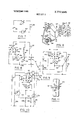
FIG. 1 shows an elevation view of the use of the alarm system of this invention with a bicycle;
FIG. 2 shows a top plan view of an embodiment of this invention along line 2-2 of FIG. 1;
FIG. 3 shows a top plan view of the invention shown in FIGS. 1 and 2 in an open position;
FIG. 4 shows the invention along line 4-4 of FIG. 3 to indicate the side elevation view of the device when it is opened;
FIG. 5 shows a bottom view of the invention along line 55 of FIG. 4;
FIG. 6 shows the gimbled trip or motion switch of this invention as seen along lines 66 of FIG. 4;
FIG. 7 shows a schematic electrical form of an audio alarm system incorporated in this invention;
FIG. 8 shows a schematic electrical form of the the embodiment of this invention;
FIG. 9 shows an electrical schematic form of an alternative embodiment of this invention;
FIG. 10 shows a schematic electrical form of an embodiment of this invention; and,
FIG. 11 is an edge view of this invention along line 1l11 of FIG. 2.
DESCRIPTION OF THE PREFERRED EMBODIMENTS Looking at FIG. 1, the alarm system 20 for use with a bicycle or motorcycle is shown attached to a bicycle 12 by connection to and around a vertical post 14 of the bicycle. The vertical post 14 is usually a part of most bicycles for purposes of providing general rigidity to the frame of the bicycle. Extending from the alarm system is a chain 16 which is wrapped around a post 18. As can be seen from the showing of FIG. 1 and the other figures, a protuberance formed as a lock dial holder 20 is shown. The lock dial holder 20 is for purposes of operating a combination lock 22. The lock dial holder 20 has three dials 21, 23, and therein for suitable rotation and operation of the lock 22.
The audio alarm system 10 has a box or cover 24 which is divided at a midline 26 and hinged by a hinge 28 in order to provide access to the interior of the box. As can be seen in FIG. 2, the center bar 14 or vertical post of a byicycle is shown through the midsection of the audio alarm 10. The vertical post 14 is located inte: riorly of the alarm box 24 by virtue of passing through openings 30 and 32 at the respective bottom and top of the case or box 24. Interiorly of the box 24 is a clamp 34 attahced thereto having two bolts 36 and 38 for securing the clamp in a tightened manner around the post 14. In other words, the clamp 34 is opened when the box 24 is secured to a bicycle and the center post 14 is passed thereinto. The bolts 36 and 38 are then secured in a tight manner so that the box 24 cannot pass over or slide up and down on the bar 14.
As can be seen from the interior of the box 24 specifically shown in FIGS. 3, 4 and 5, the hinge 28 extends along a substantial length of the box 24. The hinge 28 can be affixed to the box in a suitable manner such as by rivets 40 which are shown holding the hinge to the box.
The box 24 comprises a cover 42 and a base 44. The cover 42 is mounted so that it provides access to the inside of the box 24 by hinging over the base portion of the box 44. Interiorly of the cover 42 is a latch 46 referred to as a striker in the lock art, which is secured to the combination lock 22 by the openings 48 thereof. Thus, when the cover 42 is emplaced and secured to the base 44, the latch 46 snugly fits into and is held by the combination lock 22 through the openings 48.
The base has a substantial portion of the electrically operative elements of this invention mounted therein. The electrically operative elements generally comprise batteries 50 or a suitable power source. The batteries 50 are held to the base by a clamp 52 which tends to hold the batteries in situ through frictional engagement thereof. The batteries 50 are provided with contacts, two of which, namely contacts 54 and 56, hold the batteries in tight electrical contact. The batteries are connected to the remainder of the circuit through appropriate lines. The lines are such that they connect the circuit in a manner to be described and as seen in the schematic view 8 which will be described later. The other electrical schematic configurations can be utilized with the same physical apparatus and have the advantages described with respect to each configuration shown in FIGS. 9 and 10.
An audio alarm 62 is provided for purposes of sounding an alarm when the detection circuit is actuated. In order to cause the actuation of the audio alarm 62, a gimbled motion or trip switch generally shown at 64 is connected to the base 44 of the box 24 at a motion switch holder 68 comprising clamps 69 and 71 which have ball sockets 73 and 75.
The motion switch 64 is provided with a dielectric support 76 in the general shape of an inverted L. The dielectric support 76 is curved and can be made of a plastic material and molded to receive a support pin 78 having a ball 80 attached to the end thereof. The ball 80 seats within the socket seats 73 and which suitably clamp and accommodate the ball by means of pressure exerted from the arms 69 and 71 of a motion switch retention means 68.
The dielectric support 76 has a pair of eyelets 82 and 84 which are seated and can be molded within the dielectric material 76. The eyelets have contact washers 86 and 88 respectively associated with each eyelet. The contact washers in trun are connected to soldering points or lugs 90 and 92 from which the wires detailed in the schematic electrical views are connected and through which an electrical circuit can be completed. The eyelets 82 and 84 serve to connect a hanging contact 94 which is looped through eyelet 82 by a bend 96 and projects upwardly through eyelet 84 with an upward extension 98.
The motion switch 64 can be oriented so that when the upward projection 98 is out of contact with the eyelet 84, there will be no contact between the electrical connections 92 and 90. When the initial placement of the motion switch 64 is disoriented with respect to the support means 68 which is attached to the box 24, the upward projection 98 makes contact against the loop 84 and completes an electrical circuit from contacts 92 to 90.
The motion switch 64 is connected through a double pole double throw switch 102 which has an operating tab 104. The double pole double throw switch is shown schematically in FIG. 8 and operates the circuit by means of being connected to the motion switch by wires 106 and to the remainder of the circuit for operation thereof.
A locking cable or chain 16 which was shown in FIG. 1 is comprised of a cable section 108 and an end cap portion 110 which is seated within the box 24 within a rounded opening or an identation motion The end cap 110 can be riveted by rivets 114 which secure the end cap 110 into the base of the box 44.
The cable 108 terminates in a seating cap 116 which is seated within an indentation or rounded opening 118 of the base 44 of the box 24. The seating cap 116 is of a rounded disc shaped design having a groove 120 circumferentially surrounding the upper portion of the cap 122 so that the groove 120 can be seated against the rounded interior surface of the circumferential opening 118.
Thus, when the cable is to be locked into the box, the
The chain 108 is comprised of a vinyl or other suitable outer cover 124 and has steel flexible tubing 126, interiorly located thereof. The steel tubing 126 is such that it provides a certain degree of armor or protection against one attempting to cut the chain 16. Interiorly of the flexible steel tubing 126 is a protective tubular layer 128 surrounding a series of electrical wires 130 each comprising an insulated wire 132 having a conductor 134 therein. The wires are specifically part of the operative features of the detection circuit of this invention, and will be described in greater detail with respect to the schematic views of FIGS. 7 through 10. The cable 108 is basically a locking cable to prevent physical removal of a bicycle or object to be protected, as well as warning when the cable is cut, broken or crimped badly.
DESCRIPTION OF THE ELECTRICAL CIRCUIT Looking at FIG. 8, a schematic view is shown wherein a power source or EMF is provided. The EMF is that of the battery 50. The battery is connected to a junction point 144 of the switch 102 so that the switch 102 can cause conduction of current through the remainder of the circuit. The switching tab 104 and switch 102 are connected and configured so that the switch effectively causes contact of the poles in a double pole double throw relationship. Specifically, switch 102 has poles and contacts which go from a reset position R to a motion position M as indicated by the arrow. A set of contacts 140, 142, 144 and 146 allow a break and make situation to reset a relay that will be more fully described.
The motiron switch 64 is shown schematically having a rounded configuration or circle which is analagous to the eyelet 84. The interior contact point is analagous to the arm 94. The switch can be connected and operate such that it makes contact from arm 94 to eyelet 82 which are represented by the outer circle 65 of the schematic configuration of the motion switch 64.
The audio warning device 62 is basically a buzzer that can function mechanically or electrically to provide a certain tone when it is actuated. A relay switch 148 is shown having a coil 150 and a switch arm 152. The relay switch is shown across a set of junction points or terminals which are placed across the wires 130 of the cable 108.
The motion switch 64 is connected by the reset position R and between terminals 144 and 156. The chain 108 is also connected to terminal 156.
The relay 148 can be a reed switch of a single pole configuration which is activated by the source of EMF.
The physical configuration of the cable or chain 108 within the circuit system is such that the cable will always serve to operate the alarm when the wires 130 are shorted. Shorting of the wires, of course, can take place by breaking the outer insulation 132 of the wires 130 such that the conductors I34 come in contact with each other. More specifically, when the chain or cable 108 is broken or cut by any sort of conductive metallic material such as a wire cutter, snipper, or a pair of pliers, the conductors 134 are shorted. Thus, even though the device is not in a mode which will allow the motion switch 64 to operate, it can still effectively monitor any theft when the cable 108 is cut.
The R position resets the reed relay 148 by dropping its reed back into an operative position. This is done by utilizing the break before make configuration of the switch 102 before the switch wiper is pushed all the way over to terminals 146. In other words, when the switch from the reset position is pushed over to the make position M, it resets the reed relay through the break before make configuration of the double pole double throw switch.
ALTERNATIVE CIRCUIT CONFIGURATIONS Basic Configuration The simplest circuit configuration of this device incorporates the showing of FIG. 7. The showing of FIG. 7 is of a battery or power source 50 connected to a motion switch 64 and an audio alarm 62. A switch 160 is shown which can be utilized to turn the system on and off. The switch 160 permits the disengagement of the motion switch 64 after the arm 94 has made contact with the eyelet 84. Furthermore, while the motion switch 64 is being situated by movement within the supporting elements 71 and 69, the switch can be placed in an off position so that it does not actuate the audio alarm 62.
The foregoing configuration of FIG. 7 is specifically useful for-devices to be protected such as expensive office equipment and portable strongboxes. In this mode, the device can be internally or externally attached out of view, or in such a manner that it cannot be taken from the equipment to be protected. Once the motion switch 64 is set so that the upright extension 98 is out of contact with the eyelet 84, it can be placed in a position to further monitor any future movement of the device. Upon movement, of course, the motion switch arm 94 will contact the eyelet 84 with the upright 98 thereby completing the circuit between electrical connections and 92 so that the audio alarm 62 will operate.
Solid State Configuration Looking more specifically at FIG. 9, a source of EMF 50 is shown. A chain or cable configuration having conductors is also shown connected to a motion switch 64 and a double pole double throw switch 102. The reset R and motion M configuration is basically the same as FIG. 8 wherein the switch 102 can be moved from a break before make position. Of course, the switch moves across the terminals 144 and 142 in an analagous manner as they did of FIG. 8. The motion switch 64 is connected in a like manner except for the fact that in lieu of a reed relay or relay switch 148, an SCR (silicone controlled rectifier) 164 is provided. Current to the gate of the SCR is limited by means of a current limiting resistor 166. A capacitor 168 is also provided in order to provide stability.
The audio alarm 62 is shown connected from the SCR in a manner whereby it will operate when the SCR is forwardly biased to allow current to flow to the audio alarm. This is accomplished by the motion switch 64 completing an electrical circuit though its connections 90 and 92.
Combination Chain Circuit FIG. 10 shows a double pole double throw switch 102 having a reset R and motion M configuration analagous to the former descriptions of the same switch in FIGS. 8 and 9. The switch 102 has terminals 140, 142, 144 and 146 and goes from the reset and make position with the break before make configuration as previously described.
The chain or cable 16 is configured so that a series of conductors like those of the conductors 130 are provided within the cable. However, some of the conductors 130 are looped as in the case of conductor 170 and 132 which are looped at point 174. Furthermore, additional conductors are provided such as conductor 176 which is not connected or looped in the manner of loop 174. The conductors 176 are laterally placed alongside the conductors 170 and 132, and function in the manner to be described.
A source of EMF such as battery 50 is provided. The motion switch 64 which has the configuration shown in FIG. 6 makes contact to cause a flow of current through contacts 90 and 92. This is shown schematically by the loop 65 and inner point 94 which are analagous to the eyelet and the upstanding extension 98.
The alternative embodiment of FIG. is also provided with an audio alarm 62 and an SCR 178. A capacitor 180 is provided for purposes of stability in the same manner as the capacitor 168.
A transistor 184 is shown having a PNP configuration. The transistor 184 is biased by Resistor 186, when loop 174 is cut. A resistor 188 is utilized to bias the collector of the transistor. Resistor 190 is utilized to provide a current limiting function in the same manner as the current limiting resistor 166.
In this particular configuration, when the conductors 170 and 132 are broken or interrupted, the audio alarm 62 will be turned on. Furthermore, when conductors 176 are shorted with conductors 170 and 132, the alarm will be turned on. In effect, when the loop 174 is cut, the transistor 184 is negatively biased as a PNP transistor would be, to cause current to flow through the SCR 178. By shorting the conductors 176 with conductors 170 or 132, the transistor is eliminated in the circuit and effectively bypassed to cause the SCR 178 to be forwardly biased and again operate the audio alarm 62.
Operation of the Invention One utilizing the embodiment of FIGS. 1 through 6 and 8 for purposes of a vehicle lock firstly opens the box 24 by means of the combination lock 22. Upon opening the box 24, the switch 102 is switched to a reset mode by pushing tab 104 to the reset position. The motion switch 64 is then oriented so that the upper extension 98 is not in contact with the eyelet 84. The switch 102 is then moved to the motion position M. The box is then closed and locked with the seating cap 116 implaced within the rounded opening 118. It is preferable to have the cable 16 looped around a solid object prior to seating of the seating cap 116 within the opening 1 18. After the box 24 has been closed thereby locking seating cap 116 into the box, and the motion switch 64 has been set, the operator or the owner of the vehicle can then leave.
When the cable 16 is either cut or disturbed substantially so as to short the conductors 130, the audio alarm 62 will emanate a warning sound.
When the bicycle as seen in FIG. 1 or for that matter, any device or equipment to which the box 10 is attached is disoriented, the motion switch 64 will cause a flow of current. As can be appreciated, when the motion switch 64 is disturbed or disoriented from its initial position, arm 94 will cause the upright 98 to contact the loop 84. The contact of the loop 84 will then complete a circuit between electrical contacts 92 and 90 thereby causing the audio alarm 62 to operate.
In like manner, when the circuits of FIGS. 7, 9 and 10 are utilized the audio alarm 62 will also function LII when the motion switch 64 is disoriented from its initial position. As can be seen, the motion switch 64 and cable 16 will provide safety from theft in combination with each other.
It should be understood that the invention can be utilized not only with any form of portable equipment, but can also be utilized with the motion switch or the cable singularly or in combination. Additional embodiments can also incorporate a trickle charger to keep the battery or other source of EMF in a ready state. As a consequence, this invention has broad scope beyond the foregoing teachings and is only to be read and construed in light of the following claims.
We claim:
1. A portable alarm comprising:
a power supply;
an audio signal means;
a motion switch which is supported for operative orientation so that upon physical displacement of said motion switch, it will make electrical contact for operating said audio signal means;
a conductive cable;
a plurality of conductors within said cable connected to said audio signal means;
electrical means for connecting said motion switch and said cable to said power supply and said audio signal means for purposes of causing said audio signal means to issue an audio signal upon said motion switch making contact after disorientation or said conductors of said cable making contact or being cut; and,
a container in which the foregoing elements are mounted.
2. A alarm as claimed in claim 1 wherein said container comprises:
a hinged box;
means to mechanically link said conductive cable to said box;
a lock for maintaining said box in locked relationship; and,
means attached to said box for holding said box on a device to be protected.
3. The audio alarm system as claimed in claim 1 further comprising:
switch means for causing a cutout of the motion switch. 7
4. A portable alarm system for affixing to a moveable object comprising:
a container;
a battery mounted within said container;
electrical audio signal means within said container;
a lock for closing said container;
means for affixing said container to a piece of equipment to be protected by said alarm;
a motion switch within said container for linking said audio signal means to the battery within said container for operating said audio signal means;
a switch for disconnecting said motion switch from said audio signal means;
an electrical cable having a looped conductor for connecting said audio alarm means and said battery when the conductor is cut; and,
means for creating an audio signal when said motion switch is disoriented or said looped conductor is cut.
5. An alarm as claimed in claim 4 wherein:
said means for creating an audio signal when said mosecond electrical conductors; and
means to cause said audio signal means to issue a signal when said second conductors make contact.
8. The alarm as claimed in claim 4 further comprising:
a transistor connected to the looped conductor; and, an SCR connected to said looped conductor and the collector of said transistor at the gate of said SCR.
Claims (8)
1. A portable alarm comprising: a power supply; an audio signal means; a motion switch which is supported for operative orientation so that upon physical displacement of said motion switch, it will make electrical contact for operating said audio signal means; a conductive cable; a plurality of conductors within said cable connected to said audio signal means; electrical means for connecting said motion switch and said cable to said power supply and said audio signal means for purposes of causing said audio signal means to issue an audio signal upon said motion switch making contact after disorientation or said conductors of said cable making contact or being cut; and, a container in which the foregoing elements are mounted.
2. A alarm as claimed in claim 1 wherein said container comprises: a hinged box; means to mechanically link said conductive cable to said box; a lock for maintaining said box in locked relationship; and, means attached to said box for holding said box on a device to be protected.
3. The audio alarm system as claimed in claim 1 further comprising: switch means for causing a cutout of the motion switch.
4. A portable alarm system for affixing to a moveable object comprising: a container; a battery mounted within said container; electrical audio signal means within said container; a lock for closing said container; means for affixing said container to a piece of equipment to be protected by said alarm; a motion switch within said container for linking said audio signal means to the battery within said container for operating said audio signal means; a switch for disconnecting said motion switch from said audio signal means; an electrical cable having a looped conductor for connecting said audio alarm means and said battery when the conductor is cut; and, means for creating an audio signal when said motion switch is disoriented or said looped conductor is cut.
5. An alarm as claimed in claim 4 wherein: said means for creating an audio signal when said motion switch is disoriented comprises an SCR; and, means are provided for forwardly biasing said SCR so that when said motion switch is making contact, it will cause said forward biasing means to cause current to flow through said SCR.
6. An alarm as claimed in claim 5 further comprising: a current limiting resistor to the gate of said SCR; and a capacitor for stability within said circuit.
7. An alarm as claimed in claim 4 wherein said cable further comprises: second electrical conductors; and means to cause said audio signal means to issue a signal when said second conductors make contact.
8. The alarm as claimed in claim 4 further comprising: a transistor connected to the looped conductor; and, an SCR connected to said looped conductor and the collector of said transistor at the gate of said SCR.
Applications Claiming Priority (1)
| Application Number | Priority Date | Filing Date | Title |
|---|---|---|---|
| US21922972A | 1972-01-20 | 1972-01-20 |
Publications (1)
| Publication Number | Publication Date |
|---|---|
| US3772645A true US3772645A (en) | 1973-11-13 |
Family
ID=22818420
Family Applications (1)
| Application Number | Title | Priority Date | Filing Date |
|---|---|---|---|
| US00219229A Expired - Lifetime US3772645A (en) | 1972-01-20 | 1972-01-20 | Vehicle alarm system |
Country Status (1)
| Country | Link |
|---|---|
| US (1) | US3772645A (en) |
Cited By (49)
| Publication number | Priority date | Publication date | Assignee | Title |
|---|---|---|---|---|
| US3879721A (en) * | 1973-09-27 | 1975-04-22 | Robert A Yereance | Lock having flexible shackle with severance alarm |
| US3910081A (en) * | 1974-05-07 | 1975-10-07 | David R Pender | Locking means for bicycles and the like |
| US4057986A (en) * | 1976-07-19 | 1977-11-15 | Sarah Zolke | Self-contained alarm lock |
| US4098102A (en) * | 1977-03-17 | 1978-07-04 | Kalina Edward O | Auto safe lock |
| US4404822A (en) * | 1981-05-18 | 1983-09-20 | Green Leonard O | Pre-coiled cable-lock device |
| US4468939A (en) * | 1983-01-12 | 1984-09-04 | Olshausen Michael C | Accessory lock and article storage device for bicycles and the like |
| US4546345A (en) * | 1981-08-13 | 1985-10-08 | Honda Giken Kogyo Kabushiki Kaisha | Theft preventing device |
| GB2158979A (en) * | 1984-03-21 | 1985-11-20 | Andrew John George | Alarm equipment |
| US4577477A (en) * | 1983-01-12 | 1986-03-25 | Olshausen Michael C | Accessory lock and article storage device for bicycles and the like |
| US4591127A (en) * | 1984-04-09 | 1986-05-27 | Tuvesson Paer Ake | Suspension attachment |
| EP0225459A2 (en) * | 1985-10-26 | 1987-06-16 | Karl-Heinz Wulff | Locking device for safeguarding two-wheeled vehicles |
| US4811578A (en) * | 1983-08-18 | 1989-03-14 | John F. Masoncup | Padlock with tamper-actuated audible and/or inaudible alarm |
| EP0385800A1 (en) * | 1989-03-02 | 1990-09-05 | James Molohon | Anti-theft device |
| US5023596A (en) * | 1989-10-13 | 1991-06-11 | Datatool Alarms Limited | Bicycle alarm |
| GB2247553A (en) * | 1990-07-31 | 1992-03-04 | Weyrad Electronics Ltd | "Satellite receiver theft alarm systems" |
| WO1994008113A1 (en) * | 1992-10-01 | 1994-04-14 | Merz Metall- Und Kunststoffverarbeitungs Gmbh | Alarm lock |
| US5408212A (en) * | 1992-09-18 | 1995-04-18 | Brio Corporation | Multi-mode combination alarm and locking apparatus for bicycles, motorcycles and the like |
| GB2286476A (en) * | 1994-02-11 | 1995-08-16 | Stephen Thomas Williamson | Motion sensing alarm suitable for attachment to bicycle |
| US5497036A (en) * | 1994-10-21 | 1996-03-05 | Harley-Davidson | Motorcycle terminal box assembly |
| US5760681A (en) * | 1994-03-21 | 1998-06-02 | Oy Alektro Safeguard Ltd. | Burglar alarm activated by the movement of an object to be guarded |
| US5836002A (en) * | 1995-06-01 | 1998-11-10 | Morstein; Jason | Anti-theft device |
| GB2334801A (en) * | 1998-02-27 | 1999-09-01 | Philip Howard Gazeley | Alarm device for use with a golf bag |
| US6000251A (en) * | 1992-01-24 | 1999-12-14 | Acco Brands, Inc. | Computer physical security device |
| US6000252A (en) * | 1992-01-24 | 1999-12-14 | Acco Brands, Inc. | Computer physical security device |
| US6006557A (en) * | 1995-02-08 | 1999-12-28 | Acco Brands, Inc. | Computer physical security device |
| US6112561A (en) * | 1994-08-26 | 2000-09-05 | Acco Brands, Inc. | Security device for a portable computer |
| US6389854B1 (en) * | 2000-11-16 | 2002-05-21 | Dennis Huang | Computer lock |
| US6662602B1 (en) | 1996-11-08 | 2003-12-16 | Acco Brands, Inc. | Security device for a portable computer |
| US6735990B1 (en) | 1992-01-24 | 2004-05-18 | Acco Brands, Inc. | Computer physical security device |
| EP1657387A2 (en) * | 2004-11-11 | 2006-05-17 | BLACK & DECKER INC. | Cable lock for a security system |
| US7100404B2 (en) | 1993-10-15 | 2006-09-05 | Acco Brands Usa Llc | Computer physical security device |
| US7111479B2 (en) | 1992-01-24 | 2006-09-26 | Acco Brands Usa Llc | Computer physical security device |
| US7191623B2 (en) | 2003-07-23 | 2007-03-20 | Acco Brands Usa Llc | Computer physical security device with retractable cable |
| US7204106B2 (en) | 2001-08-13 | 2007-04-17 | Acco Brands Usa Llc | Portable electronic device physical security |
| US7409842B2 (en) | 2002-07-24 | 2008-08-12 | Acco Brands Usa Llc | Lock for securing an article on display |
| US7415852B1 (en) | 2004-10-06 | 2008-08-26 | Acco Brands Usa Llc | Tubular lock with theft deterrent |
| US7500371B2 (en) | 2005-11-18 | 2009-03-10 | Acco Brands Usa Llc | Locking device with passage |
| US7614266B2 (en) | 2007-10-15 | 2009-11-10 | Acco Brands Usa Llc | Security apparatus with reset mechanism |
| GB2463526A (en) * | 2008-09-17 | 2010-03-24 | Lee Fisher | Alarmed cycle lock |
| US7997106B2 (en) | 2009-05-29 | 2011-08-16 | Acco Brands Usa Llc | Security apparatus including locking head and attachment device |
| USD651889S1 (en) | 2011-04-19 | 2012-01-10 | Acco Brands Usa Llc | Security apparatus |
| US8230707B2 (en) | 2007-05-25 | 2012-07-31 | ACCO Brands Corporation | Security system with lock interface member with multiple apertures |
| WO2014012564A1 (en) * | 2012-07-20 | 2014-01-23 | Velolock Ltd. | Locking device for a bicycle |
| US20150040465A1 (en) * | 2013-08-08 | 2015-02-12 | Nelson Development Group, LLC | Snapping Fish Stringer |
| US9786153B2 (en) | 2014-11-26 | 2017-10-10 | Justin London | Multi-modal tracking locator alarm system |
| US20180208071A1 (en) * | 2015-07-21 | 2018-07-26 | Ride On Consulting, S.L. | Anchoring system for bicycles |
| EP3483015A1 (en) * | 2017-11-14 | 2019-05-15 | Siti Eood | Waterproof and shock-resistant gps tracker |
| US20200074535A1 (en) * | 2018-08-31 | 2020-03-05 | Beijing Boe Display Technology Co., Ltd. | Vehicle for public rental |
| US10633889B2 (en) * | 2017-06-15 | 2020-04-28 | Michael Mendel Tsur | Cable lock |
Citations (3)
| Publication number | Priority date | Publication date | Assignee | Title |
|---|---|---|---|---|
| US2947830A (en) * | 1958-09-02 | 1960-08-02 | Herbert A Goss | Vehicle alarm switch |
| US3644921A (en) * | 1969-12-30 | 1972-02-22 | Cat Products Inc | Alarm with trundle switch |
| US3670301A (en) * | 1971-03-15 | 1972-06-13 | Pete Pakulak | Vehicle anti-theft device |
-
1972
- 1972-01-20 US US00219229A patent/US3772645A/en not_active Expired - Lifetime
Patent Citations (3)
| Publication number | Priority date | Publication date | Assignee | Title |
|---|---|---|---|---|
| US2947830A (en) * | 1958-09-02 | 1960-08-02 | Herbert A Goss | Vehicle alarm switch |
| US3644921A (en) * | 1969-12-30 | 1972-02-22 | Cat Products Inc | Alarm with trundle switch |
| US3670301A (en) * | 1971-03-15 | 1972-06-13 | Pete Pakulak | Vehicle anti-theft device |
Cited By (72)
| Publication number | Priority date | Publication date | Assignee | Title |
|---|---|---|---|---|
| US3879721A (en) * | 1973-09-27 | 1975-04-22 | Robert A Yereance | Lock having flexible shackle with severance alarm |
| US3910081A (en) * | 1974-05-07 | 1975-10-07 | David R Pender | Locking means for bicycles and the like |
| USRE29521E (en) * | 1974-05-07 | 1978-01-24 | Locking means for bicycles and the like | |
| US4057986A (en) * | 1976-07-19 | 1977-11-15 | Sarah Zolke | Self-contained alarm lock |
| US4098102A (en) * | 1977-03-17 | 1978-07-04 | Kalina Edward O | Auto safe lock |
| US4404822A (en) * | 1981-05-18 | 1983-09-20 | Green Leonard O | Pre-coiled cable-lock device |
| US4546345A (en) * | 1981-08-13 | 1985-10-08 | Honda Giken Kogyo Kabushiki Kaisha | Theft preventing device |
| US4468939A (en) * | 1983-01-12 | 1984-09-04 | Olshausen Michael C | Accessory lock and article storage device for bicycles and the like |
| US4577477A (en) * | 1983-01-12 | 1986-03-25 | Olshausen Michael C | Accessory lock and article storage device for bicycles and the like |
| US4811578A (en) * | 1983-08-18 | 1989-03-14 | John F. Masoncup | Padlock with tamper-actuated audible and/or inaudible alarm |
| GB2158979A (en) * | 1984-03-21 | 1985-11-20 | Andrew John George | Alarm equipment |
| US4591127A (en) * | 1984-04-09 | 1986-05-27 | Tuvesson Paer Ake | Suspension attachment |
| EP0225459A3 (en) * | 1985-10-26 | 1988-11-17 | Karl-Heinz Wulff | Locking device for safeguarding two-wheeled vehicles |
| EP0225459A2 (en) * | 1985-10-26 | 1987-06-16 | Karl-Heinz Wulff | Locking device for safeguarding two-wheeled vehicles |
| EP0385800A1 (en) * | 1989-03-02 | 1990-09-05 | James Molohon | Anti-theft device |
| US5023596A (en) * | 1989-10-13 | 1991-06-11 | Datatool Alarms Limited | Bicycle alarm |
| GB2247553A (en) * | 1990-07-31 | 1992-03-04 | Weyrad Electronics Ltd | "Satellite receiver theft alarm systems" |
| US7143614B1 (en) | 1992-01-24 | 2006-12-05 | Acco Brands Usa Llc | Computer physical security device |
| US6155088A (en) * | 1992-01-24 | 2000-12-05 | Acco Brands, Inc. | Computer physical security device |
| US7111479B2 (en) | 1992-01-24 | 2006-09-26 | Acco Brands Usa Llc | Computer physical security device |
| US7100403B2 (en) | 1992-01-24 | 2006-09-05 | Acco Brands Usa Llc | Computer physical security device |
| US6735990B1 (en) | 1992-01-24 | 2004-05-18 | Acco Brands, Inc. | Computer physical security device |
| US6588241B1 (en) | 1992-01-24 | 2003-07-08 | Acco Brands, Inc. | Computer physical security device |
| US6000251A (en) * | 1992-01-24 | 1999-12-14 | Acco Brands, Inc. | Computer physical security device |
| US6000252A (en) * | 1992-01-24 | 1999-12-14 | Acco Brands, Inc. | Computer physical security device |
| US6553794B1 (en) | 1992-01-24 | 2003-04-29 | Acco Brands, Inc. | Computer physical security device |
| US5408212A (en) * | 1992-09-18 | 1995-04-18 | Brio Corporation | Multi-mode combination alarm and locking apparatus for bicycles, motorcycles and the like |
| WO1994008113A1 (en) * | 1992-10-01 | 1994-04-14 | Merz Metall- Und Kunststoffverarbeitungs Gmbh | Alarm lock |
| US7100404B2 (en) | 1993-10-15 | 2006-09-05 | Acco Brands Usa Llc | Computer physical security device |
| US7201029B2 (en) | 1993-10-15 | 2007-04-10 | Acco Brands Usa Llc | Computer physical security device |
| GB2286476A (en) * | 1994-02-11 | 1995-08-16 | Stephen Thomas Williamson | Motion sensing alarm suitable for attachment to bicycle |
| US5760681A (en) * | 1994-03-21 | 1998-06-02 | Oy Alektro Safeguard Ltd. | Burglar alarm activated by the movement of an object to be guarded |
| US6112561A (en) * | 1994-08-26 | 2000-09-05 | Acco Brands, Inc. | Security device for a portable computer |
| US5497036A (en) * | 1994-10-21 | 1996-03-05 | Harley-Davidson | Motorcycle terminal box assembly |
| US6006557A (en) * | 1995-02-08 | 1999-12-28 | Acco Brands, Inc. | Computer physical security device |
| US5836002A (en) * | 1995-06-01 | 1998-11-10 | Morstein; Jason | Anti-theft device |
| US6662602B1 (en) | 1996-11-08 | 2003-12-16 | Acco Brands, Inc. | Security device for a portable computer |
| GB2334801A (en) * | 1998-02-27 | 1999-09-01 | Philip Howard Gazeley | Alarm device for use with a golf bag |
| US6389854B1 (en) * | 2000-11-16 | 2002-05-21 | Dennis Huang | Computer lock |
| US7204106B2 (en) | 2001-08-13 | 2007-04-17 | Acco Brands Usa Llc | Portable electronic device physical security |
| US7409842B2 (en) | 2002-07-24 | 2008-08-12 | Acco Brands Usa Llc | Lock for securing an article on display |
| US7647796B2 (en) | 2003-07-23 | 2010-01-19 | Acco Brands Usa Llc | Computer physical security device with retractable cable |
| US7191623B2 (en) | 2003-07-23 | 2007-03-20 | Acco Brands Usa Llc | Computer physical security device with retractable cable |
| US7415852B1 (en) | 2004-10-06 | 2008-08-26 | Acco Brands Usa Llc | Tubular lock with theft deterrent |
| EP1657387A2 (en) * | 2004-11-11 | 2006-05-17 | BLACK & DECKER INC. | Cable lock for a security system |
| EP1657387A3 (en) * | 2004-11-11 | 2010-02-17 | BLACK & DECKER INC. | Cable lock for a security system |
| US7963132B2 (en) | 2005-11-18 | 2011-06-21 | Acco Brands Usa Llc | Locking device with passage |
| US7730751B2 (en) | 2005-11-18 | 2010-06-08 | Acco Brands Usa Llc | Locking device with passage |
| US7500371B2 (en) | 2005-11-18 | 2009-03-10 | Acco Brands Usa Llc | Locking device with passage |
| US8230707B2 (en) | 2007-05-25 | 2012-07-31 | ACCO Brands Corporation | Security system with lock interface member with multiple apertures |
| US7614266B2 (en) | 2007-10-15 | 2009-11-10 | Acco Brands Usa Llc | Security apparatus with reset mechanism |
| GB2463526A (en) * | 2008-09-17 | 2010-03-24 | Lee Fisher | Alarmed cycle lock |
| US7997106B2 (en) | 2009-05-29 | 2011-08-16 | Acco Brands Usa Llc | Security apparatus including locking head and attachment device |
| US8001812B2 (en) | 2009-05-29 | 2011-08-23 | Acco Brands Usa Llc | Security apparatus including locking head |
| US8042366B2 (en) | 2009-05-29 | 2011-10-25 | Acco Brands Usa Llc | Security apparatus including attachment device |
| USD651889S1 (en) | 2011-04-19 | 2012-01-10 | Acco Brands Usa Llc | Security apparatus |
| USD660682S1 (en) | 2011-04-19 | 2012-05-29 | Acco Brands Usa Llc | Security apparatus |
| USD661975S1 (en) | 2011-04-19 | 2012-06-19 | ACCO Brands Corporation | Attachment device for security apparatus |
| USD670553S1 (en) | 2011-04-19 | 2012-11-13 | ACCO Brands Corporation | Attachment device for security apparatus |
| WO2014012564A1 (en) * | 2012-07-20 | 2014-01-23 | Velolock Ltd. | Locking device for a bicycle |
| US20150204112A1 (en) * | 2012-07-20 | 2015-07-23 | Velolock Ltd. | Locking device for a bicycle |
| US20150040465A1 (en) * | 2013-08-08 | 2015-02-12 | Nelson Development Group, LLC | Snapping Fish Stringer |
| US9974287B2 (en) * | 2013-08-08 | 2018-05-22 | Nelson Development Group, LLC | Snapping fish stringer |
| US9786153B2 (en) | 2014-11-26 | 2017-10-10 | Justin London | Multi-modal tracking locator alarm system |
| US10410506B2 (en) | 2014-11-26 | 2019-09-10 | Justin London | Multi-modal tracking locator alarm system |
| US11069219B2 (en) | 2014-11-26 | 2021-07-20 | Justin London | Multi-modal tracking locator alarm system |
| US20180208071A1 (en) * | 2015-07-21 | 2018-07-26 | Ride On Consulting, S.L. | Anchoring system for bicycles |
| US10828991B2 (en) * | 2015-07-21 | 2020-11-10 | Ride On Consulting, S.L. | Electric bicycles anchoring system |
| US10633889B2 (en) * | 2017-06-15 | 2020-04-28 | Michael Mendel Tsur | Cable lock |
| EP3483015A1 (en) * | 2017-11-14 | 2019-05-15 | Siti Eood | Waterproof and shock-resistant gps tracker |
| US20200074535A1 (en) * | 2018-08-31 | 2020-03-05 | Beijing Boe Display Technology Co., Ltd. | Vehicle for public rental |
| US10937086B2 (en) * | 2018-08-31 | 2021-03-02 | Beijing Boe Display Technology Co., Ltd. | Vehicle for public rental |
Similar Documents
| Publication | Publication Date | Title |
|---|---|---|
| US3772645A (en) | Vehicle alarm system | |
| US3993987A (en) | Locking device having an integral alarm system | |
| US5836002A (en) | Anti-theft device | |
| US3755778A (en) | Cycle burglar alarm | |
| US5889463A (en) | Anti-theft device | |
| US5408213A (en) | Portable breakaway alarm system | |
| US5191314A (en) | Combination anti-theft lock and alarm | |
| US4663611A (en) | Alarm lock | |
| US5023596A (en) | Bicycle alarm | |
| US5727405A (en) | Alarm padlock | |
| US4092641A (en) | Security interlock switch system for smoke detectors and the like | |
| US4151506A (en) | Lock and alarm apparatus | |
| EP0275756A1 (en) | Proximity detector between a metallic mass and an element under electric tension | |
| US4034337A (en) | Vehicle alarm apparatus | |
| US6191685B1 (en) | Bicycle theft protection system | |
| US3914756A (en) | Portable alarm actuated by attempted theft | |
| US4379281A (en) | Alarm system for bicycles and the like | |
| US4315244A (en) | Vehicle alarms | |
| US5389916A (en) | Simplified shortcircuiting and circuit-breaking alarm means for planar or linear conductors | |
| US5059945A (en) | Remote alarm module and alarm system | |
| US20100050535A1 (en) | Detector of attempt to break a lock, lock, door and alarm system comprising such a detector | |
| US3754224A (en) | Security alarm actuating device | |
| US3924254A (en) | Anti-intrusion alarm system | |
| US4821025A (en) | Vehicle cover alarm system | |
| GB2181932A (en) | Improvements in fishing rod rests |