US3772657A - Magnetic tape data handling system employing dual data block buffers - Google Patents
Magnetic tape data handling system employing dual data block buffers Download PDFInfo
- Publication number
- US3772657A US3772657A US00203245A US3772657DA US3772657A US 3772657 A US3772657 A US 3772657A US 00203245 A US00203245 A US 00203245A US 3772657D A US3772657D A US 3772657DA US 3772657 A US3772657 A US 3772657A
- Authority
- US
- United States
- Prior art keywords
- data
- input
- memory unit
- responsive
- memory
- Prior art date
- Legal status (The legal status is an assumption and is not a legal conclusion. Google has not performed a legal analysis and makes no representation as to the accuracy of the status listed.)
- Expired - Lifetime
Links
Images


Classifications
-
- G—PHYSICS
- G06—COMPUTING; CALCULATING OR COUNTING
- G06F—ELECTRIC DIGITAL DATA PROCESSING
- G06F3/00—Input arrangements for transferring data to be processed into a form capable of being handled by the computer; Output arrangements for transferring data from processing unit to output unit, e.g. interface arrangements
- G06F3/01—Input arrangements or combined input and output arrangements for interaction between user and computer
- G06F3/02—Input arrangements using manually operated switches, e.g. using keyboards or dials
- G06F3/023—Arrangements for converting discrete items of information into a coded form, e.g. arrangements for interpreting keyboard generated codes as alphanumeric codes, operand codes or instruction codes
- G06F3/0232—Manual direct entries, e.g. key to main memory
-
- G—PHYSICS
- G06—COMPUTING; CALCULATING OR COUNTING
- G06F—ELECTRIC DIGITAL DATA PROCESSING
- G06F3/00—Input arrangements for transferring data to be processed into a form capable of being handled by the computer; Output arrangements for transferring data from processing unit to output unit, e.g. interface arrangements
- G06F3/01—Input arrangements or combined input and output arrangements for interaction between user and computer
- G06F3/048—Interaction techniques based on graphical user interfaces [GUI]
- G06F3/0487—Interaction techniques based on graphical user interfaces [GUI] using specific features provided by the input device, e.g. functions controlled by the rotation of a mouse with dual sensing arrangements, or of the nature of the input device, e.g. tap gestures based on pressure sensed by a digitiser
- G06F3/0489—Interaction techniques based on graphical user interfaces [GUI] using specific features provided by the input device, e.g. functions controlled by the rotation of a mouse with dual sensing arrangements, or of the nature of the input device, e.g. tap gestures based on pressure sensed by a digitiser using dedicated keyboard keys or combinations thereof
Definitions
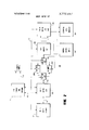
- ABSTRACT There is disclosed a data handling system including input-output means, intermediate memory means and principal memory means, together with data transfer and processing control logic. Input and output parallel to serial and serial to parallel and code conversion capability are provided. input-output temporary storage and data processing are provided by the intermediate memory which comprises a pair of random access memory units or the like.
- the principal memory is a magnetic tape system, preferably employing a magnetic tape cassette as a memory medium.
- the system is usable in various ways, for example as a data terminal capable of local keyboard and/or remotely controlled data storage and transmission. Data input and output may be in parallel or serial form and a variety of data rates and data code words may be accommodated without system modification.
- the system accumulates data in a first one of the intermediate memory units through the input-output means.
- the capacity of the first unit is reached, the entire data block is transferred to the principal memory at a high speed.
- data is being transferred to the principal memory from the first intermediate memory unit, data is accumulated in the second intermediate memory unit. Transfer of data from the first intermediate memory unit is completed before the capacity of the second intermediate memory unit for incoming data is reached.
- the second intermediate memory unit is full, its contents are transferred to the principal memory, and data is again accumulated in the first intermediate memory.
- an entire block of data is transferred at high speed from the principal memory into a first intermediate memory and is thereafter provided through the input-output means to suitable data utilization devices at a data rate compatible with such devices. While data is being transmitted from the first intermediate memory unit, a data block is rapidly entered into the second intermediate memory unit. When the first unit is empty data is transmitted from the second unit, and the first unit is refilled.
- system error checking and correction on a character-by-character basis, message identification (search) based on selectable identifying code characteristics and compatibility with a a variety of keyboard controlled devices or other data input and output devices, and automatic and manual data gathering and processing machinery.
- This invention relates to a keyboard controlled data storage and retrieval system.
- the invention is useful in a variety of commercial and technical datahandling applications, but finds particular utility as a terminal. for two-way data transmission or for message transmission in a system such as TWX or TELEX," and will be described in this environment.
- the system may be used in a variety of other ways, for example, as an automatic typewriting and composing system, an audio-dictation transcriber, in process control or as a means of data gathering, storage and control, or, in conjunction with a small-scale arithmetic processor such as a cash register, calculator, etc., as a minimum-scale computer capable of direct interface with larger, more versatile data processing machines, or even as all of these combined.
- Our parent application Ser. No. 123,187 is directed to so-called terminal equipment" used for obtaining access to and controlling a computer which is relatively inexpensive, reliable and durable, and sufficiently versatile, to be compatible with commonly used information transmission and processing formats, and data transmission rates.
- the equipment described here is particularly useful in the latter regard, to an extent even exceeding that of the system of application Ser. No. 123,187.
- the present system also improves the utilization of available communication channels for information transfer directly from one computer to another, requiring externally high information generating and handling capacity for the terminal equipment, and also for applications in which information is generated manually on a keyboard and/or received by an electro mechanical printer.
- One magnetic tape system described employs multibit code words uniquely identifying data characters which are stored as generated or received in parallel, i.e., all of the bits for each code word are simultaneously recorded in parallel tracks on the magnetic tape.
- the system of our parent application of the present application record multi-bit character code information serially on a single track, rather than in parallel.
- This appraoch eliminates many of the disadvantages of parallel recording such as the need for wide tape, multiple head recording apparatus, etc., but creates several new difficulties and complications not encountered in a parallel recording system.
Abstract
There is disclosed a data handling system including input-output means, intermediate memory means and principal memory means, together with data transfer and processing control logic. Input and output parallel to serial and serial to parallel and code conversion capability are provided. Input-output temporary storage and data processing are provided by the intermediate memory which comprises a pair of random access memory units or the like. The principal memory is a magnetic tape system, preferably employing a magnetic tape cassette as a memory medium. The system is usable in various ways, for example as a data terminal capable of local keyboard and/or remotely controlled data storage and transmission. Data input and output may be in parallel or serial form and a variety of data rates and data code words may be accommodated without system modification. Broadly stated, for operation in the record mode, the system accumulates data in a first one of the intermediate memory units through the input-output means. When the capacity of the first unit is reached, the entire data block is transferred to the principal memory at a high speed. While data is being transferred to the principal memory from the first intermediate memory unit, data is accumulated in the second intermediate memory unit. Transfer of data from the first intermediate memory unit is completed before the capacity of the second intermediate memory unit for incoming data is reached. Thus, when the second intermediate memory unit is full, its contents are transferred to the principal memory, and data is again accumulated in the first intermediate memory. For playback, an entire block of data is transferred at high speed from the principal memory into a first intermediate memory and is thereafter provided through the input-output means to suitable data utilization devices at a data rate compatible with such devices. While data is being transmitted from the first intermediate memory unit, a data block is rapidly entered into the second intermediate memory unit. When the first unit is empty data is transmitted from the second unit, and the first unit is refilled. Among the features provided by the system are error checking and correction on a character-by-character basis, message identification (search) based on selectable identifying code characteristics and compatibility with a a variety of keyboard controlled devices or other data input and output devices, and automatic and manual data gathering and processing machinery.
Description
United States Patent 1 1 Marsalka et a1.
1 Nov. 13, 1973 [75] Inventors: Joseph P. Marsalka, Columbus;
Charles F. Spademan, Worthington, both of Ohio [73] Assignee: M1,, Inc., Columbus, Ohio [22] Filed: Nov. 30, 1971 [21] Appl. No; 203,245
Related U.S. Application Data [63] Continuation-impart of Ser, No. 123,187, March 11,
Primary Examiner-Gareth D. Shaw Attorney-Robert E. Leblanc et al.
[57] ABSTRACT There is disclosed a data handling system including input-output means, intermediate memory means and principal memory means, together with data transfer and processing control logic. Input and output parallel to serial and serial to parallel and code conversion capability are provided. input-output temporary storage and data processing are provided by the intermediate memory which comprises a pair of random access memory units or the like. The principal memory is a magnetic tape system, preferably employing a magnetic tape cassette as a memory medium. The system is usable in various ways, for example as a data terminal capable of local keyboard and/or remotely controlled data storage and transmission. Data input and output may be in parallel or serial form and a variety of data rates and data code words may be accommodated without system modification.
Broadly stated, for operation in the record mode, the system accumulates data in a first one of the intermediate memory units through the input-output means. When the capacity of the first unit is reached, the entire data block is transferred to the principal memory at a high speed. While data is being transferred to the principal memory from the first intermediate memory unit, data is accumulated in the second intermediate memory unit. Transfer of data from the first intermediate memory unit is completed before the capacity of the second intermediate memory unit for incoming data is reached. Thus, when the second intermediate memory unit is full, its contents are transferred to the principal memory, and data is again accumulated in the first intermediate memory.
For playback, an entire block of data is transferred at high speed from the principal memory into a first intermediate memory and is thereafter provided through the input-output means to suitable data utilization devices at a data rate compatible with such devices. While data is being transmitted from the first intermediate memory unit, a data block is rapidly entered into the second intermediate memory unit. When the first unit is empty data is transmitted from the second unit, and the first unit is refilled.
Among the features provided by the system are error checking and correction on a character-by-character basis, message identification (search) based on selectable identifying code characteristics and compatibility with a a variety of keyboard controlled devices or other data input and output devices, and automatic and manual data gathering and processing machinery.
92 Claims, 32 Drawing Figures United States Patent 1 [111 3,772,657
Marsalka et al. Nov. 13, 1973 uue COUPLER To REMOTE AND TERMINAL swncmm; 4
J Y m2) 204A r INIAMEM. I
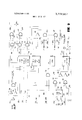
mpm INPUT} 3 i i 0mm mm 7, COUPLING COUPLING mm 1 uun PRINTER IW UNIT CONTROL STATE INPUTS WDKIATOR 216' ZIB PAIENTEDMW 13 m3 3.772.657 SHEEI D18! 17 LINE COUPLER AND SWITCHING APPARATUS M m COMMUNICATION CHANNEL us I40 END OF ERROR END OF MESSAGE TAPE 304 302 a r a! r w 30s TAPE MIND LOAD STOP J k J p J 308 3|0 ,3|2
( PLAY SEARCH FIG. 3
L J & p J
r w a fi REC [:3 em 0F TAPE 3M PLAY LOCAL MESSAGE ERASE J L J J Pi J PATENTEDNUY 13 I975 SHEET 03 0F 17 START START Foams/Bar 8433 MS/CHAR rm 4c I I I I I I I? START A we 8 14MB FIG 7|) HG. TC
THE
FIG. "3
j A B H H H mwn um mm HI. I. Hun Du A I 0 55 SS 88 A 7 i HO MO 0 I 0 0 U0 F f A B SDn DnS SR 3 R PATENT DRDT Ta T975 3772.657
SHEET 0U OF 17 SERIAL DATA FROM I/O SHIFT NTER EOM H05 5|6uV- FROM I/OREG Q EN REGISTER 602) 5l6lx) REGISTER CONTROL M602) (MT. PREs 514D UNIT (606) (606] I "514m sERTAL DATA 56 1 IC sET SERIAL DATA OUT {H6} PARALLEL DATA TO MEMORY (530) RECORD PARALLEL ENTER 50 0 E; (602) TAPE STORE OUTPUT PRINT CONTROL M LOGIC SERIAL mm (606) B1 A! sTART PRTRT OUT CYCLE (550) IZOQLEE UNIT T02; PRINTER READY Em! lm slam SEEM/520 5|6OT] FROMSHREG P504) 53D MEMOUT 4 s02 i I ((M6)) M (6021 :Q ETE M (606) CHAR. ,1 SET (e02) REQQRD IDENT. (606,
W512i)! (s02) ,uo CLAMP a ('02, KEYBOARD (530) iQM x.EER A SEARCH B-T APE A5O fid (530) LOGIC A-IAEE A550 DATA To (606T L E UNIT Ji;0 (530T PRINTER (5301 ATA T DATA )FER L AL (610) Q LL 560 DATA sTRoDE 42) l-1Jl% JEKRC- g g (602) 8 ma: REF. RE L g 55. 525 i MEMORY UNIT MEMORY UNIT 5 R E, 2;; D-
g MEMORY CONTROL LOGIC UNIT [6IO) (e04) 532 a n (502) (604) (560,506){ (560) (602] (602) (e22) (602) (602) T620) T580; (502) e s PATENTEHIIIIVI3 I975 3,772,657
509 MASTER 84.48 KHz INN) (560,606) [6041 EOM CODE }(504I SEQUENCE CONTROL LOGIC UNIT DATA STROBE TA RCT KEY ua[5U2,530, TRACK nvssmw (53mm RECORD mums (530,604) .:0IL c lggfi PATENTEDNUV 13 I973 SHEET 15 0f 17 an own GNN MAGNETIC TAPE DATA HANDLING SYSTEM EMPLOYING DUAL DATA BLOCK BUFFERS INTRODUCTION The present application is a continuation-in-part of copending application Ser. No. 123,187, filed Mar. 1 l, 1971, entitled Magnetic Tape Data System. The disclosure of said application Ser. No. 123,187 is fully incorporated by reference herein.
This invention relates to a keyboard controlled data storage and retrieval system. The invention is useful in a variety of commercial and technical datahandling applications, but finds particular utility as a terminal. for two-way data transmission or for message transmission in a system such as TWX or TELEX," and will be described in this environment. However, with appropriate augmentation the system may be used in a variety of other ways, for example, as an automatic typewriting and composing system, an audio-dictation transcriber, in process control or as a means of data gathering, storage and control, or, in conjunction with a small-scale arithmetic processor such as a cash register, calculator, etc., as a minimum-scale computer capable of direct interface with larger, more versatile data processing machines, or even as all of these combined. These features are provided in a system which is simple and inexpensive in relation to other keyboard controlled terminals, yet possesses capabilities not available even in the more expensive and complex systems.
BACKGROUND As explained in application Ser. No. 123,187, recent developments in data transmission, storage and processing have resulted in ready availability of access to computers for commercial and technical users, through established data transmission networks, such as telephone or teletypewriter systems at reasonable cost, for services such as space reservation, inventory control, centralized accounting, etc.
Our parent application Ser. No. 123,187 is directed to so-called terminal equipment" used for obtaining access to and controlling a computer which is relatively inexpensive, reliable and durable, and sufficiently versatile, to be compatible with commonly used information transmission and processing formats, and data transmission rates. The equipment described here is particularly useful in the latter regard, to an extent even exceeding that of the system of application Ser. No. 123,187. The present system also improves the utilization of available communication channels for information transfer directly from one computer to another, requiring externally high information generating and handling capacity for the terminal equipment, and also for applications in which information is generated manually on a keyboard and/or received by an electro mechanical printer.
Basically, these systems are organized to provide temporary storage of generated or received data before transmission or utilization. Our parent application describes various known systems employing key-board control devices and remote data couplers to produce a punched paper tape or magnetic tape record of the information to be transmitted or received, and details various advantages and disadvantages of such systems.
One magnetic tape system described employs multibit code words uniquely identifying data characters which are stored as generated or received in parallel, i.e., all of the bits for each code word are simultaneously recorded in parallel tracks on the magnetic tape.
Among the noted disadvantages are the requirement for several parallel tape tracks, the need to augment the character code for remote transmission to include extra start, stop, and error checking bits, with the consequent need either to suppress all but the information bits for storage, and to generate (or regenerate) these bits when information is to be transmitted, or else to provide a sufficient number of parallel tape tracks for recording the entire code word.
For the foregoing reasons, the system of our parent application of the present application record multi-bit character code information serially on a single track, rather than in parallel. This appraoch eliminates many of the disadvantages of parallel recording such as the need for wide tape, multiple head recording apparatus, etc., but creates several new difficulties and complications not encountered in a parallel recording system.
Among these are the need to allow the tape transport mechanism to reach its intended operating speed before recording or playback without running the tape continuously between characters.
As will be understood, utilization of tape space is very inefficient if the tape runs continuously with no incoming data (as between characters) since much (actually, most) of the tape is empty. Even if the tape stops between characters, nothing is being recorded during the start-up and slow-down" time and tape utilization is not still not efficient. To overcome this, efforts have been made to develop a tape transport not subject to a substantial start" and stop delay, but no equipment meeting the various requirements appears to be available at reasonably low cost.
Other problems include compatibility between the operating speed of the keyboard (and the output printer) and the tape transport mechanism to permit maximum bit storage density on the tape, and maximum playback speed, and control of the operating speed of the tape transport mechanism. Tape transports are available which provide a high degree of speed control, but this is an important factor in the cost of transport, and thus ultimately in the overall cost of the system.
Another disadvantage of heretofore proposed serial recording systems is the difficulty of incorporating certain information processing functions such as error correction or message address or identifier searching.
Moreover, where it is desired to make the terminal system compatible with more than one information transmission format, it may be necessary to record information at one speed and to play it back at a different speed. This can be a substantial problem since data transmission rates currently employed or contemplated vary from [10 baud (bits/second) to 4800 band, or even higher. Since a relatively inexpensive transport could not possibly run fast enough to achieve a suitable bit density on tape for the highest baud rates, intermediate storage of some type has been found essential. All of the foregoing is detailed in our parent application.
BRIEF DESCRIPTION OF THE INVENTlON The present invention like that of our parent application, seeks to avoid the foregoing disadvantages of the serial and parallel recording formats in a serial system
Claims (92)
1. A system for handling data in the form of multibit character code words comprising: input-output means adapted to be connected to an external data source; intermediate memory means comprising first and second memory units, each having the capacity for storing a block of data comprising a pluraity of character code words; a principal memory for storage of a plurality of data blocks; and control logic means for establishing a recording operation sequence comprising entry of data from said external source through said input-output means, serial accumulation of the bits making up blocks of data in alternate ones of said intermediate memory units, and serial transfer of the bits making up data to said principal memory from each of said memory units after accumulation therein of a complete data block, said control logic means including selection means having a first state in which the first memory unit is coupled to said input/output means and the second memory unit is coupled to said principal memory, and a second state in which the second memory unit is coupled to said input/output means, and the first memory unit is coupled to said principal memory, first means for effecting transfer of date one bit at a time from said input/output means to said first memory unit when said selection means is in said first state, and from said input/output means to said second memory unit when said selection means is in said second state, second means for effecting data transfer of bits comprising character code words from said second memory unit to said principal memory on a serial bit at a time transfer basis when said selection means is in said first state and from said second memory unit to said principal memory when said selection means is in said second state, first control means for actuating said first transfer means in response to incoming data from said external source, means for sensing when entry of said block of data in one of said intermediate memory units has been completed, second control means responSive to said sensing means for switching the state of said selection means, and for actuating said second transfer means to transfer the block of data just accumulated in one of said intermediate memory units to said principal memory a bit at a time, and, error correction means connected to said memory unit for deleting an undesired character from a predetermined memory unit by reversing the recording operation sequence for said predetermined memory unit.
2. A system as defined in claim 1 wherein said input/output means includes multiple bit storage means, means responsive to the bits of an externally generated character code word from said external source to generate an additional bit, the value of which is a function of the parity of the incoming code word, and means for entering said incoming code word together with said additional bit in said storage means.
3. A system as defined in claim 1 wherein said error correction means includes means for generating an error correction command signal and means responsive to the absence of data stored in the input/output means coupled memory unit due to the readout thereof into said principal memory and to the generation of said error correction command signal to switch the state of said selection means, and then to delete a predetermined end portion of the data block in the input/output means coupled memory unit by reversing the recording operation; and further means responsive to said switch-over means to prepare said principal memory to re-store at least a new predetermined end portion in said input/output means coupled memory unit after the data block therein is again completed by additional incoming data.
4. A system as defined in claim 1 wherein said sensing means comprises means responsive to accumulation in the input/output means coupled memory unit of a predetermined number of data bits to generate a control signal, said second control means being responsive to said control signal to actuate said second transfer means, and said selection means being responsive to said control signal to change from one state to the other.
5. A system as defined in claim 1 further comprising means for storing a reference code word representing a message termination character, means connected to said reference storage means and said input/output means to compare an incoming character code word with said reference code word, means for generating a coincidence signal when said incoming character code word matches said reference code word, and logic means responsive to said coincidence signal for actuating said second control means and said selection means.
6. A system as defined in claim 5 wherein said logic means includes means responsive to said coincidence signal for assuring storage in the input/output means coupled memory unit of said message termination character, means responsive to completion of storage of said message termination character to load a succession of format bits of a particular value into said last mentioned memory unit until a complete data block has been accumulated, and means responsive to operation of said sensing means for preventing the loading of format bits.
7. A system as defined in claim 1 wherein said input/output means includes means for temporarily storing incoming data from said external source; and means responsive to an incoming character code word to transfer a previously received character code word from said input/output storage means one of said said input/output associated memory unit.
8. A system as defined in claim 1 wherein each of said memory units includes a plurality of separate memory sites for storing the individual bits comprising a data block; and wherein said second transfer means comprises means to actuate each of said memory sites in sequence to provide the contents thereof to said principal memory, means for generating a timing pulse concurrently with the actuation of each memory site, and means for storing said timing pulse in said principal memory together with thE associated data bit.
9. A system for handling data in the form of multibit character code words comprising: input/output means adapted to be connected to an external utilization device; intermediate memory means comprising first and second memory units each having capacity for storing a block of data comprising a plurality of character code words; a principal memory for storage of a plurality of data blocks; and control logic means for establishing a playback operation sequence comprising serial bit-by-bit entry of a block of data in alternate ones of said memory units from said principal memory, and transfer of a block of data from each of said memory units in turn after entry of a data block therein to said external utilization device through said input/output means; said control logic means including selection means having a first state in which the first memory unit is coupled to said input/output means and the second memory unit is coupled to said principal memory, and a second state in which the second memory unit is coupled to said input/output means and the first memory unit is coupled to said principal memory, first means for effecting transfer of data from said first memory unit to said input/output means, when said selection means is in said first state, and to said input/output means from said second memory unit when said selection means is in said second state; second means for effecting data transfer from said input/output means to an external utilization device, third means for transferring data in the form of bits comprising character code words from said principal memory to said second memory unit on a serial bit at a time transfer basis when said selection means is in said first state, and from said principal memory to said first memory unit when said selection means is in said second state, first and second control means for actuating said first and second transfer means to provide data to said utilization device, and third control means responsive to transfer of a block of data from one of said intermediate memory units to said utilization device for switching the state of said selection means and for actuating said third transfer means to enter a block of data into said principal memory coupled memory unit on a bit at a time basis, said input/output means including means responsive to the bits of an outgoing character code word to test for an error in said code word, and means responsive to detection of an error for preventing said erroneous code word from being provided to said utilization device.
10. A system as defined in claim 9 wherein said second transfer means includes first means for providing data to said external utilization device in parallel form with all of the bits defining a character code word appearing simultaneously; second means for providing data to said utilization device in serial form with each of the bits defining a character code word appearing in sequence; wherein said first transfer means is operative to provide data to said input/output means one bit at a time.
11. A system as defined in claim 9 further including means responsive to detection of an erroneous code word to suppress said erroneous code word, and to substitute another code word therefor.
12. A system as defined in claim 9 wherein said third control means comprises means responsive to accumulation in said principal memory coupled memory unit of a predetermined number of data bits for temporarily halting data storage therein, means responsive to transfer from said input/output means coupled memory unit to said input/output means of said predetermined number of bits for generating a control signal; said selection means being responsive to said control signal to switch states, and said third transfer means being operative in response to said control signal.
13. A system as defined in claim 9 wherein the end of a message is identified by a particular terminal character, wherein said third control means includes means for providing a Second control signal in response to transfer of said particular character to said input/output means; and logic means responsive to said second control signal for terminating said playback sequence.
14. A system as defined in claim 13 wherein said logic means includes means operative to assure switching of said selection means and actuation of said third transfer means to enter a block of data into the principal memory coupled memory unit before said playback sequence is terminated.
15. A system as defined in claim 13 wherein said input/output means includes means for temporarily storing character code words provided by said input/output means coupled memory unit, means to initiate transfer of a previously stored character code word to said external utilization device, and means responsive to transfer of a character code word from said temporary storage means to transfer another code word to said input/output means from the input/output means coupled memory unit; and wherein said logic means is responsive to said second control signal to assure transfer out of any data stored in said temporary storage means before said playback sequence is terminated.
16. A system as defined in claim 9 wherein the end of a message is identified by a particular terminal character, wherein said third control means includes means for providing a second control signal in response to transfer of said particular character to said input/output means; and logic means including first and second cycle means, said first cycle means being responsive to said second control signal to prevent utilization by said input/output means of further data transferred from said input/output means coupled memory unit, and said second cycle means being responsive to operation of said first cycle means and to occurrence of the next of said first control signals to prevent transfer of data from the input/output coupled memory unit to the input/output means.
17. A system as defined in claim 9 wherein said principal memory contains a plurality of control pulses, each data bit being associated with one of said control pulses; wherein each of said intermediate memory units includes a plurality of separate memory sites for storing the bits comprising a data block, wherein said control logic means includes means to operate said principal memory to generate data pulses and the associated control pulses; and means responsive to said control pulses to actuate said memory sites in sequence to transfer the data pulses associated with said control pulses to said sequence of memory sites of said principal memory coupled memory unit.
18. A system as defined in claim 9 wherein said control logic means includes search operation means for establishing a search operation sequence to locate a particular combination of characters stored in said principal memory, said search operation means comprising means for storing a reference representing said particular combination of characters, means for generating an external search command, means responsive to said search command to initiate the playback operation sequence, further means responsive to said search command to inhibit operation of said second transfer means, means for comparing said stored reference with data provided to said input/output means and for providing a coincidence signal when said particular combination of characters is located, and means responsive to said coincidence signal for terminating said search operation sequence.
19. A system as defined in claim 18 further including timing means for controlling the rate of data transfer from the input/output means coupled memory unit for the playback operation sequence, said timing means being responsive to said search command to establish a data transfer rate for the search operation equal to the fastest rate available for playback operation.
20. A system as defined in claim 18 including means responsive to transfer of all available data from said principal memory to terminate said search operation, eveN if said search is not successfully completed.
21. A memory system for storage and retrieval of information in the form of multibit character code words, comprising input/output means, first coupling means connected to said input/output means and adapted to be connected to an external data source for connecting said data source to said input/output means and second coupling means connected to said input/output means and adapted to be connected to an external data utilization device for connecting said input/output means to said device; intermediate memory means comprising first and second memory units, each having capacity for storing a block of data comprising a number of character code words; data storage means adapted to receive a memory medium as a principal memory for the system; selection means having a first state in which the first memory unit is coupled to the input/output means and the second memory unit is coupled to said data storage means, and a second state in which the second memory unit is coupled to the input/output means and the first memory unit is coupled to said data storage means; first means for transferring data one bit at a time between said input/output means and said first memory unit when said selection means is in said first state, and between said input/output means and said second memory unit when said selection means in in said second state; second means for transferring information one bit at a time between said second memory unit and said data storage means when said selection means is in said first state and between said first memory unit and said data storage means when said selection means is in said second state, and logic means for controlling the information transfer operations for said system.
22. A system as defined in claim 21 further including clock means for generating primary timing signals, means for selecting a data transfer bit rate for the system, means responsive to said selecting means and to said clock means for generating a first pulse train at a frequency less than the clock frequency corresponding to said selected bit rate; wherein said first coupling means includes means for receiving data one bit at a time at a bit rate which is a sub-multiple of the frequency of said first pulse train; and wherein said logic means includes counter means responsive to said first pulse train and to an actuating signal to generate a series of timing pulses at said sub-multiple frequency with the first pulse in predetermined time relation to said activating signal, sensing means responsive to incoming data to generate said activating signal, and means responsive to said timing pulses for operating said input/output means to accept said incoming data, and to transfer said data to the input/output means coupled intermediate memory unit at a rate determined by said submultiple bit rate.
23. A system as defined in claim 22 wherein said input/output means includes means for temporarily storing incoming data in response to said timing pulses, and means responsive to said timing pulses for operating said first transfer means to transfer previously stored data bits from said input/output storage means to the input/output coupled intermediate memory unit.
24. A system as defined in claim 22 including means responsive to said clock means for generating a second pulse train at a frequency substantially exceeding the frequency of said first pulse train, sensing means responsive to accumulation in the input/output means coupled intermediate memory unit of an entire block of data for generating a first control signal, means in said logic means responsive to said first control signal to switch the states of said selection means and further means responsive to said control signal for operating the data storage means coupled intermediate memory unit to transfer data one bit at a time to said data storage means at a bit rate equal to the frequency of said second pulse train.
25. A system as defined in claim 24 further including means reSponsive to said second pulse train for storing a timing bit in said principal memory means concurrently with each data bit stored therein.
26. A system as defined in claim 22 wherein each character code word commences with a predetermined non-information bearing bit; wherein said sensing means is responsive to said non-information bearing bit to activate said counter to advance in response to the pulses of said first pulse train, said counter including means to provide a first timing pulse at a predetermined count corresponding to the nominal center of the bit period of the first information bearing bit of the incoming character code word, and means for providing further timing pulses at a succession of counts corresponding to the nominal centers of the bit periods for the other information bearing bits of said incoming character code word, means for collecting said timing pulses to form a train of pulses, and means for deactivating and resetting said counter when a predetermined maximum count is reached.
27. A system as defined in claim 26 wherein the frequency of said first pulse train is eight times the nominal bit rate.
28. A system as defined in claim 22 wherein said second coupling means includes means for transmitting data one bit at a time at a bit rate which is a sub-multiple of the frequency of said first pulse train; means in said logic means actuating said counter means to generate said timing pulses at said sub-multiple frequency, means for actuating the input/output means coupled intermediate memory unit, said input/output means and said second coupling means in response to said timing pulses to transfer data from said last mentioned input/output means coupled intermediate memory unit through said input/output means to said utilization device at said sub-multiple frequency.
29. A system as defined in claim 28 wherein said counter includes means for generating an additional pulse preceding said timing pulses by an interval equal to the interval between data bits at said selected data bit rate, and means responsive to said additional pulse for generating an initial bit for transmission as part of each character code word.
30. A system as defined in claim 23 further including means responsive to said clock means to generate a second pulse train at a frequency substantially higher than the frequency of said first pulse train, means responsive to said second pulse train for generating a second series of timing pulses; wherein said second transfer means includes means for storing one of said second timing pulses concurrently with a data bit in said principal memory, means for retrieving said second timing pulses, means responsive to said retrieved second timing pulses for activating said second transfer means to enter data from the principal memory into the data storage means coupled intermediate memory unit; and further including means responsive to accumulation in said last mentioned intermediate memory unit of an amount of data equal to the storage capacity thereof generating a control signal, means responsive to said control signal for switching the state of said selection means, and thereafter for actuating said first transfer means to transfer data from the input/output means coupled intermediate memory unit one bit at a time to said input/output means, further means responsive to said control signal for reactuating said second transfer means to enter further data from said principal memory to said data storage means coupled intermediate memory unit while data from said input/output means coupled intermediate memory is being transferred to said input/output means.
31. A system as defined in claim 30 wherein the end of a complete message is identified by a particular terminal character, wherein said logic means includes means responsive to the presence of a terminal character in said input/output means to generate a second control signal, means responsive to said second control signal to actuate said second coupling means to transfeR said terminal character to said external utilization device, means for thereafter preventing operation of said second coupling means, means responsive to transfer of said terminal character to said external utilization device for operating the input/output means coupled intermediate memory unit to transfer the data therein to said input/output unit means.
32. A system, as defined in claim 31 further including means responsive to the completion of the transfer of the contents of said input/output means coupled memory unit to said input/output means for switching the state of said selection means, and for thereafter actuating said second transfer means to enter additional data from said principal memory to the data storage means coupled intermediate memory unit.
33. A system as defined in claim 31 wherein the transfer of data from said last mentioned input/output means coupled memory unit after detection of said terminal character in said input/output means is at a rate substantially exceeding the frequency of said first pulse train.
34. A system as defined in claim 21 wherein the end of a complete message is identified by a particular terminal character, wherein said sensing means includes means responsive to the presence of said terminal character in said input/output means to generate a second control signal, means responsive to said second control signal to actuate said first transfer means to enter said terminal character in the input/output means coupled intermediate memory unit, means responsive to entry of said terminal character and to the total number of characters in said last mentioned input/output mean coupled memory unit to enter additional characters into said memory unit, and means responsive to entry of a complete data block in said last mentioned input/output means coupled memory unit to prevent entry of additional characters, to switch the state of said selection means, and thereafter to operate said second transfer means to transfer the contents of the data storage means coupled intermediate memory unit to said data storage means.
35. A system as defined in claim 21 wherein said memory medium comprises a magnetic recording tape: wherein said data storage means includes tape transport means and drive means for said transport means; wherein said second transfer means includes first and second recording circuits for recording first and second information tracks; and wherein said logic means includes means for generating a data transfer pulse train, means to initiate a data record operation sequence comprising means for activating said transport drive means for continuous operation, means for operating the data storage means coupled intermediate memory unit in response to said data transfer pulse train to transfer data to said first recording circuit in bit-by-bit synchronism with said data transfer pulses, and means for coupling said data transfer pulse train to said second recording circuit to store a track of timing pulses on said tape with the timing pulses in synchronism with the bits of said data track.
36. A system as defined in claim 35 wherein said logic means further includes means responsive to transfer of the entire contents of the data storage means coupled intermediate memory unit to the tape for deactivating said transport drive means.
37. A system as defined in claim 35 including means responsive to activation of said transport drive means to delay the actuation of the data storage means coupled intermediate memory unit and said recording circuits for a predetermined interval to allow said transport to reach its normal operating speed.
38. A system as defined in claim 35 wherein said first and second recording circuits include means for converting the binary code input to a non-return-to-zero code for recording.
39. A system as defined in claim 35 wherein said second transfer means includes first and second playback circuits associated with the first and second information tracks of a tape serving as the principal meMory medium, and wherein said logic means includes means to initiate a data playback sequence comprising means for actuating said transport drive means for continuous operation, means for connecting said first playback circuit to the data storage means coupled intermediate memory unit, means connected to said second playback circuit and responsive to timing pulses in said second tape information track for activating said data storage means coupled intermediate memory unit to store the data bit associated with each timing pulse, and means responsive to playback of a block of data equal to the capacity of the data storage means coupled intermediate memory unit for deactivating said transport drive means.
40. A system as defined in claim 39 wherein said deactivating means comprises means for stopping said transport drive means after a predetermined interval if timing pulses are not detected by said second playback circuit.
41. A system as defined in claim 39 wherein said deactivating means comprises means for counting the number of data bits entered in the data storage means coupled memory unit and means for stopping said transport drive when a predetermined bit count has been reached.
42. A system as defined in claim 39 including means responsive to actuation of said transport drive means to delay activation of the data storage means coupled intermediate memory unit for a predetermined tape start-up interval to allow said transport to reach its normal operating speed, and means for inhibiting operation of said deactivating means during said start-up delay interval.
43. A system as defined in claim 42 wherein said logic means includes means connected to said second playback circuit and responsive to an externally generated command to override said deactivation means until a timing pulse has been played back from said timing track through said second playback circuit.
44. A memory system as defined in claim 21 wherein said second transfer means is adapted to retrieve data from a magnetic tape serving as said principal memory medium, said tape having recorded thereon a first track of data pulses and a second track of timing pulses synchronized with said data pulses, groups of said pulses being separated by blank portions of said tape to define individual blocks of data having a number of bits equal to the capacity of said intermediate memory units, wherein said second transfer means includes separate playback circuits for said data and timing tracks; wherein said data storage means comprises magnetic tape transport means and transport drive means; and wherein said logic means includes means for establishing a playback operating sequence comprising means for activating said transport drive means, control means responsive to timing pulses played back by said timing track playback circuit to activate the data storage coupled intermediate memory unit to store a data pulse associated with each timing pulse, and cycle termination means responsive to playback of an entire data block for deactivating said transport drive means and for preventing further storage of data in said data storage means coupled intermediate memory unit.
45. A system as defined in claim 44 including means responsive to actuation of said transport drive means to prevent storage of data in said data storage means coupled; memory unit and to inhibit said cycle termination means for a predetermined start-up delay period to allow said transport to reach its normal operating speed.
46. A system as defined in claim 45 wherein said logic means includes means for establishing a load operation sequence comprising means responsive to an external load command to activate said transport drive means and to deactivate said cycle termination means, and means responsive to the start of playback of information by said second transfer means to reactivate said cycle termination means.
47. A system as defined in claim 46 wherein said means for reactivating said cycle termination means is responsive to the fIrst timing track pulse of a data block.
48. A system as defined in claim 21 wherein said input/output means includes storage means for at least one multibit character code word, wherein said first coupling means comprises means for receiving incoming character code words in serial form at several different nominal bit rates, wherein said logic means includes means for generating a first pulse train at a frequency which is a high multiple of the highest of said nominal bit rates, dividing means responsive to said first pulse train to generate a second pulse train at a frequency equal to a selected nominal bit rate, means responsive to the first bit of an incoming character code word to generate an activating signal for said dividing means, said dividing means being operative to generate the first pulse of said second pulse train after a predetermined number of pulses of said first pulse train following said activating signal, and for generating succeeding pulses of said second pulse train at a frequency equal to said nominal bit rate, means for activating said input/output storage means in response to said second pulse train to store incoming data bits in synchronism with the pulses of said second pulse train, and means for deactivating said dividing means after a predetermined number of pulses of said second pulse train have been generated.
49. A system as defined in claim 48 wherein said first coupling means includes means for receiving incoming code words in parallel form, wherein said logic means includes means responsive to appearance of a code word in parallel form in said first coupling means to generate said activating signal for said dividing means and also to generate a parallel data entry control signal, means responsive to said parallel data entry control signal to enter the bits of said incoming code word simultaneously into said input/output storage means, said input/output storage means thereafter being responsive to said second pulse train to transfer data stored therein into the intermediate memory unit coupled to said input/output means on a bit-by-bit basis.
50. A system as defined in claim 21 wherein said data storage means includes transport means for receiving a magnetic tape as said memory medium, and drive means for said tape transport, said drive means including means for operating said transport in a forward direction, means for operating said transport in a reverse direction, means cooperating with said transport for sensing the beginning of a tape, and means cooperating with said transport for sensing the end of a tape; and werein said logic means includes means for actuating said forward drive means during data transfer between said data means and the data storage means coupled memory unit and means responsive to the sensing of the end of a tape for deactivating said forward drive means.
51. A system as defined in claim 50 including means for generating an external rewind command signal and wherein said logic means includes means responsive to said external rewind command signal to operate said reverse drive means, and means responsive to the sensing of the beginning of the tape for deactivating said reverse drive means.
52. A system as defined in claim 51 further including means for generating an external tape erase command signal and wherein said logic means includes means for establishing a tape erase operation sequence comprising means responsive to said external tape erase command signal to operate said forward drive means, means responsive to sensing of the end of the tape and to said tape erase command signal to deactivate said forward drive means and to activate said reverse drive means, means in said second data transfer means responsive to said tape erase command signal to erase the tape, and means responsive to the sensing of the beginning of the tape and said tape erase command signal to terminate said erase operation sequence.
53. A system as defined in claim 50 further including means for generating an eXternal tape erase command signal and means responsive to said external tape erase command signal for operating said data storage means to erase all information stored on a tape adapted to be carried by said transport.
54. A system as defined in claim 21 including means for generating an external error command signal and wherein said logic means includes means responsive to said external error correction command signal to delete a character code word from the input/output means coupled intermediate memory unit.
55. A system as defined in claim 21 wherein said data storage means is adapted to receive a magnetic tape cassette as said principal memory medium.
56. A system as defined in claim 21 wherein said input/output means further includes means coupled thereto to detect the existence of an error in a character to be transferred to said utilization device, and means responsive to detection of an error for preventing transfer of the erroneous code word.
57. A system as defined in claim 21 wherein said input/output means includes a shift register having a number of stages sufficient to store an entire character code word; means responsive to said incoming character code word from an external serial data source for operating said shift register and the input/output means coupled intermediate memory units to enter said incoming code word bit by bit into said shift register and to transfer a code word previously entered in said shaft register one bit at a time to said intermediate memory unit.
58. A system as defined in claim 57 wherein said input/output means includes means for connecting the bits of an incoming character code word from a parallel data source simultaneously to respective stages of said shift register and wherein said logic means includes means for entering said code word into said shift register stages and for thereafter advancing said shift register a sufficient number of times to transfer said code word one bit at a time to said input/output means coupled intermediate memory unit.
59. A system as defined in claim 57 wherein said input/output means includes means responsive to the bits of an incoming code word to generate an additional bit, the value of which is a function of the parity of the incoming code word, and means for entering said additional bit in one of the bit positions of said shift register, together with the associated code word.
60. A system as defined in claim 21 wherein each of said intermediate memory units comprises a random access memory having a plurality of individually accessible memory sites, said random access memory being operable in storage and retrieval operating modes, and means for selectively activating said individual memory sites for storage or retrieval operation.
61. A system as defined in claim 21 wherein each of said intermediate memory units includes a plurality of individually accessible memory sites, said memory units being selectively operable to store a data bit in an addressed memory site or to read out a data bit from an addressed memory site, means coupled to each of said memory units to address the individual memory sites thereof and further means coupled to each of said memory units to select storage or read-out operation for a particular memory site addressed by said addressing means.
62. A system as defined in claim 21 wherein said logic means includes means for establishing data storage and retrieval modes of operation for the system, means for generating signals indicative of the selected mode, means responsive to said storage mode signal to activate said first coupling means, said input/output means, said first transfer means, and said input/output means coupled intermediate memory unit to store data in said input/output means coupled memory unit, means responsive to storage in said input/output means coupled memory unit of a complete data block from said input/output means for switching the state of said selection means, and for activating said data storage means, said second tRansfer means, and said data storage means coupled intermediate memory unit to transfer the data therein to said data storage means, and means responsive to the transfer of a block of data to said data storage means to deactivate said second transfer means, said data storage means, and the data storage means coupled intermediate memory unit.
63. A system as defined in claim 62 wherein each of said intermediate memory units includes a plurality of individually accessible memory sites, said memory units being selectively operable to write a data bit in an addressed memory site or to read out a data bit from an addressed memory site, means coupled to each of said memory units to address the individual memory sites thereof in a particular sequence, means responsive to the arrival of data at said input/otput means to advance the addressing means for the input/output means coupled intermediate memory unit through a portion of its sequence, read/write control means coupled to each of said memory units to select read or write operation for a particular memory site addressed by said addressing means, and wherein said logic means includes means cooperating with said read/write control means for the first intermediate memory unit and responsive to said storage mode signal to operate said first memory unit to write data when the selection means is in its first state, and to read out data when the selection means is in the second state, and means cooperating with the read/write control means for said second memory unit and responsive to said storage mode signal to operate said second memory unit to read data when the selection means is in its first state, and to write data when the selection means is in the second state.
64. A system as defined in claim 63 further including means for generating an error command signal and error correction means comprising countback means responsive to said external error command signal and to said storage mode signal for operating the addressing means for the input/output means coupled memory unit to re-address the memory site corresponding to the first bit of the last character entered in said input/output means coupled memory unit, whereby the portion of the address sequence corresponding to the last entered character is repeated when new data appears at said input/output means.
65. A system as defined in claim 64 wherein said addressing means is an up-down counter, wherein said advancing means is operative to advance said counter on a step-by-step basis by a number of counts equal to the number of bits to be stored in the associated memory unit, and wherein said countback means comprises means to reduce the count in said counter by a number of counts equal to the number of bits to be corrected.
66. A system as defined in claim 64 including switch-over means responsive to said error correction command signal, and to a predetermined address state of the input/output means coupled memory unit to switch the state of the selection means whereby the intermediate memory unit previously coupled to said data storage means becomes coupled to the input/output means and further including means responsive to said error correction signal for maintaining the address of the intermediate memory unit now coupled to said input/output means at the address corresponding to the last available memory site until operation of said count-back means commences.
67. A system as defined in claim 66 further including means responsive to operation of said switch-over means to prepare said principal memory to re-record at least a portion of the last data block transferred thereto.
68. A system as defined in claim 67 wherein said memory medium is a magnetic tape, wherein said data storage means includes tape transport means operable in a forward direction to receive data transferred from one of said intermediate memory units, and wherein said enabling means comprises means responsive to operation of said switch-over means to operate said tape in a reverse directioN until the entire portion of the tape containing the previously recorded data block has been rewound.
69. A memory system as defined in claim 63 further comprising means for storing a reference code word representing a message termination character, means connected to said reference storage means and said input/output means to compare an incoming character code word with said reference code word, means for generating a coincidence signal when said incoming character code word matches said reference code word, and logic means responsive to said coincidence signal for actuating the address advancing means for the input/output means coupled memory unit to assure storage therein of said message termination character, means responsive to completion of storage of said message termination character to operate the address advancing means for the input/output means coupled memory unit to load a succession of format bits therein of a particular value, and means responsive to accumulation of a complete data block for preventing the loading of format bits.
70. A system as defined in claim 69 wherein said means for preventing the loading of formatting bits comprises means responsive to the addressing means for the input/output means coupled memory unit reaching the address corresponding to the last available memory site of the input/output means coupled intermediate memory unit to inhibit the operation of said loading means.
71. A system as defined in claim 21 wherein said logic means includes means for establishing data storage and retrieval modes of operation for the system, means for generating signals indicative of the selected mode, means responsive to a retrieval mode signal to activate said second coupling means, said input/output means, said first transfer means, and said input/output means coupled intermediate memory unit to transfer data from said input/output means coupled memory unit through said input/output means to an external data utilization device, means responsive to transfer from said input/output means coupled memory unit of a complete data block to said input/output means for switching the state of said selection means, and for activating said principal memory, said second transfer means, and said data storage means coupled intermediate memory unit to transfer another data block from said principal memory to the intermediate memory unit coupled to said data storage means and means responsive to the transfer of said block of data from said principal memory to deactivate said second transfer means, said principal memory, and the intermediate memory unit coupled to said data storage means.
72. A system as defined in claim 71 wherein each of said intermediate memory units includes a plurality of individually accessible memory sites, said memory units being selectively operable to write a data bit in an addressed memory site or to read out a data bit from an addressed memory site, means coupled to each of said memory units to address the individual memory sites thereof in a particular sequence, read/write control means coupled to each of said memory units to select read or write operation for a particular memory site addressed by said addressing means, and wherein said logic means includes means cooperating with the read/write control means for said first intermediate memory unit and responsive to said retrieval mode signal to operate said first memory unit to read out data when the selection means is in its first state, and to write data when the selection means is in the second state, and means cooperating with the read/write control means for said second memory unit and responsive to said retrieval mode signal to operate said second memory unit to write data when the selection means is in its first state, and to read out data when the selection means is in the second state.
73. A system as defined in claim 72 wherein the end of a complete message is identified by a particular terminal character, and wherein said logic means includes means foR storing a reference code word corresponding to said message termination character, means connected to said reference storage means and said input/output means to compare an outgong character code word with said reference code word, means for generating a coincidence signal when said outgoing character code word matches said reference code word, and logic means responsive to said coincidence signal for actuating the address advancing means for the input/output means coupled memory unit to continue the same through its operating sequence, means for sensing the end of said operating sequence, and means responsive to the end of said operating sequence for terminating the operation of said address advancing means.
74. A system as defined in claim 71 wherein the beginning of a message is identified by a multiple character recognition code, and wherein said logic means includes means for establishing a search mode of operation to locate a particular recognition code comprising means for storing reference characters constituting a recognition code, means for generating an external search command signal and means responsive to said external search command signal, and to said retrieval mode signal to enter said storage means, a particular recognition code, means responsive to completion of entry in said storage means of said recognition code for initiating operation of the system in its removal data retrieval mode, means for comparing the contents of the data provided to said input/output means by the intermediate memory unit coupled thereto with said stored recognition code, means responsive to a match between said recognition code, and the data in said input/output means to terminate said search operation.
75. A memory system for storage and retrieval of information in the form of multibit character code words, comprising input/output means, first coupling means adapted to receive data from an external data source, and adapted to provide data to an external data utilization device; intermediate memory means comprising first and second memory units, each having capacity for storing a block of data comprising a number of character code words, each of said intermediate memory units having a plurality of individually accessible memory sites, said memory units being selectively operable to write a data bit in an addressed memory site or to read out a data bit from an addressed memory site; counter means associated with each of said memory units to address the individual memory sites thereof; read/write control means coupled to each of said memory units to select read or write operation for an addressed memory site; data storage means comprising transport means adapted to handle a magnetic tape as a principal memory for said system, record circuitry for coupling data to said tape, and playback circuitry for receiving data from said tape; selection means having a first state in which the first memory unit is coupled to the input/output means and the second memory unit is coupled to said data storage means, and a second state in which the second memory unit is coupled to the input/ouput means and the first memory unit is coupled to said data storage means; mode selection means for establishing data storage and retrieval modes of system operation, and for providing signals representative of the selected mode; clock means for generating a first pulse train, an actuating signal, counter means responsive to said first pulse train and to said actuating signal to generate a series of timing pulses with the first of said timing pulses in predetermined time relation to said actuating signal; first transfer means for transferring data between said input/output means and the input/output means coupled memory unit; second transfer means including said record and playback circuitry for transferring data between the data storage means coupled memory unit and said data storage means; data transfer control means responsive to said mode selection signals for operating the read/write control meanS, said first and second transfer means, and said intermediate memory units such that, when the respective address counters are operated, the input/output means coupled memory unit is conditioned to write data for the information storage mode of operation, and to read out data for the information retrieval mode of operation, and the data storage means coupled memory unit is conditioned to read out data for the information storage mode of operation, and to write data for the information retrieval mode of operation; means responsive to said data storage mode signal and to incoming data to generate said actuating signal for said timing pulse generating counter; means for generating an external playback initiation signal; means responsive to said retrieval mode signal and to said external playback initiation signal to generate a succession of said actuating signals for said timing pulse generating counter; means responsive to said timing pulses to advance the addressing counter for the input/output means coupled memory unit one count for each timing pulse, means responsive to a predetermined first count in the addressing counter for the input/output means coupled memory unit corresponding to the address of the last memory site to generate a first switching signal; means responsive to said first switching signal to switch the state of said selection means; means responsive to said first switching signal to reset the address counters for said first and second memory units to a predetermined second count corresponding to the address of the first memory site; further means responsive to said first switching signal to start said tape transport; means responsive to operation of said tape transport and said first pulse train to generate a control pulse train; means responsive to said control pulse train and said storage mode signal for advancing the address counter for the data storage means coupled memory unit; means adapted to store on the tape, each control pulse along with the corresponding data pulse for the data storage means coupled memory unit; means responsive to said retrieval mode signal and to control pulses stored on said tape to advance the address counter for the data storage means coupled memory unit; means responsive to said predetermined first count in the address counter for the data storage means coupled memory unit and to said storage mode signal to generate a second switching signal; and means responsive to said second switching signal to stop said tape transport and to terminate said control pulse train.
76. A system as defined in claim 75 including means responsive to said first switching signal to delay the generation of the control pulse train, and to inhibit operation of said recording circuit for a predetermined interval to allow said tape transport to reach its normal operating speed.
77. A system as defined in claim 76 including means connected to said playback circuit for sensing control pulses recorded on said tape, means for stopping said tape transport after a predetermined interval if control pulses are not detected by said sensing means; and means for inhibiting operation of said transport stopping means during the predetermined start-up delay interval.
78. A system as defined in claim 77 further including means for establishing a load operation sequence comprising means responsive to an external load command to place said selection means in its second state and to said retrieval mode signal to activate said transport drive means and to deactivate said transport stopping means; means responsive to the next control pulse detected by said sensing means to reactivate said transport stopping means; and means responsive to said external load command to said first count in the address counter for said first intermediate memory unit to generate said first switching signal.
79. A memory system as defined in claim 75 wherein said second transfer means includes first and second record and first and second playback circuits, said first reCord circuit and said first playback circuit being associated with a first tape track for data pulses, and a second record circuit and said second playback circuit being associated with a separate tape track for recording said control pulses.
80. A system as defined in claim 75 wherein said input/output means is adpated to accept incoming character code words serially commencing with a predetermined non-information bearing bit; wherein said means to activate said timing pulse generating counter is responsive to said non-information bearing bit in an incoming character code word; said counter including means to provide a first timing pulse at a predetermined count corresponding to the nominal center of the bit period of the first information bearing bit of the incoming character code word; means for providing further timing pulses at a succession of counts corresponding to the nominal centers of the bit periods for the other information bearing bits of said incoming character code word, means for collecting said timing pulses to form said series of pulses, and means for deactivating and resetting said counter when a predetermined maximum count is reached.
81. A system as defined in claim 80 wherein said input/output means is adapted to accept incoming code words in parallel form, wherein said means to actuate said timing pulse generating counter is responsive to appearance of a code word in parallel form to generate said actuating signal, and also to generate a parallel data entry control signal, means responsive to said parallel data entry control signal to enter the bits of said incoming code word simultaneously into said input/output means, and means responsive to said series of timing pulses to transfer data from said input/output means into the input/output means coupled intermediate memory unit on a bit-by-bit basis.
82. A system as defined in claim 81 wherein said input/output means comprises a shift register having a number of stages sufficient to store an entire character code word, and wherein said first coupling means includes means adapted to couple data serially between said shift register and serial external equipment and in parallel between said shift register and parallel external equipment; and wherein said first transfer means comprises means for coupling data serially between said shift register and the input/output means coupled memory unit.
83. A system as defined in claim 81 wherein said first coupling means includes means for transmitting data one bit at a time at a bit rate which is equal to the repetition rate of said timing pulses; and wherein said timing pulse generating counter includes means for generating an additional pulse preceding said timing pulses by an interval equal to the interval between data bits at said data bit rate, and means responsive to said additional pulse for generating an initial bit for transmission as part of each character code word.
84. A system as defined in claim 75 including error correction control logic comprising means for generating an error correction signal, means responsive to said error correction signal and to said storage mode signal to generate said actuating signal for said timing pulse generating counter; and means responsive to said error correction signal to operate the address counter for the input/output means coupled memory unit in a reverse direction in response to each of said timing pulses.
85. A memory system as defined in claim 84 wherein said error correction control means includes means responsive to said predetermined second count in the address counter for the input/output means coupled memory unit to generate said first switching signal; means responsive to said error correction signal to inhibit reset of said intermediate memory address counters in response to said first switching signal; means responsive to said first switching signal and said error correction signal to operate said tape transport unit in a reverse direction; means for actuating said playback circuit dUring said reverse operation; means connected to said playback circuit for sensing recorded control pulses; and means for stopping said tape transport after a predetermined interval if control pulses are not detected by said sensing means.
86. A system as defined in claim 75 including means for establishing a search mode of operation for locating a recognition code comprising a combination of characters stored in said tape comprising reference character storage means; means for generating a reference storage signal; means responsive to said reference storage signal, to said retrieval mode signal, and to incoming data to store said data in said character storage means; means responsive to storage of said recognition code in said character storage means for generating a search operation signal and said playback initiation signal; means responsive to said search operation signal to inhibit operation of said first coupling means; means for comparing data provided to said input/output means from said input/output means coupled memory unit with the data contained in said character storage means and for generating a coincidence signal when said data match; and means responsive to said coincidence signal for terminating said search operation.
87. A system as defined in claim 86 wherein said system is capable of handling data at a variety of data rates; and wherein said clock means is operative to provide said first pulse train during a search operation at a frequency such that the repetition rate of said timing pulses is equal to or greater than the maximum data bit rate at which the system can operate.
88. A system as defined in claim 86 wherein said character storage means comprises a plurality of latch circuits, one of said latch circuit being provided for each bit of said recognition code; means for coupling said latch circuits to said input/output means; and means for actuating said latch circuits to receive data from said input/output means when an incoming character is present.
89. A system as defined in claim 88 wherein said input/output means includes a shift register having a sufficient number of bit positions to store the complete recognition code; wherein each of said latch circuits is connected to one of the shift register bit positions; and wherein said comparing means comprises a plurality of individual comparator circuits connected to one of said latch circuits and to the corresponding bit position of the shift register.
90. A system as defined in claim 75 wherein the end of a complete message is identified by a particular terminal character; and further including means connected to said input/output means for sensing said terminal character and for generating a coincidence signal when said character is detected, means responsive to said coincidence signal for generating an actuating signal for said timing pulse generating counter; means responsive to said storage mode signal and the last one of a series of timing pulses following said coincidence signal to generate a series of control pulses; means for operating the address counter for the input/output associated memory unit in response to said second control pulse train; and means responsive to said first switching signal for preventing generation of said series of control pulses.
91. A system as defined in claim 90 further including means responsive to said coincidence signal and said retrieval mode signal for generating said actuating signal for said timing pulse generating counter; and means responsive to the last one of a series of timing pulses following said coincidence signal for preventing further operation of timing pulse generating counter.
92. A system as defined in claim 75 wherein the frequency of said control pulse train substantially exceeds the repetition rate for said series of timing pulses.
Applications Claiming Priority (1)
| Application Number | Priority Date | Filing Date | Title |
|---|---|---|---|
| US20324571A | 1971-11-30 | 1971-11-30 |
Publications (1)
| Publication Number | Publication Date |
|---|---|
| US3772657A true US3772657A (en) | 1973-11-13 |
Family
ID=22753126
Family Applications (1)
| Application Number | Title | Priority Date | Filing Date |
|---|---|---|---|
| US00203245A Expired - Lifetime US3772657A (en) | 1971-11-30 | 1971-11-30 | Magnetic tape data handling system employing dual data block buffers |
Country Status (1)
| Country | Link |
|---|---|
| US (1) | US3772657A (en) |
Cited By (22)
| Publication number | Priority date | Publication date | Assignee | Title |
|---|---|---|---|---|
| US3970997A (en) * | 1974-08-29 | 1976-07-20 | Honeywell Information Systems, Inc. | High speed peripheral system interface |
| US4016531A (en) * | 1975-04-28 | 1977-04-05 | Mobil Oil Corporation | System for recording seismic reflection signals in serial-by-trace format |
| US4064553A (en) * | 1974-11-15 | 1977-12-20 | Casio Computer Co., Ltd. | Information processor |
| US4079234A (en) * | 1975-12-12 | 1978-03-14 | Casio Computer Co., Ltd. | Manual key input apparatus |
| US4158228A (en) * | 1971-12-27 | 1979-06-12 | Hewlett-Packard Company | Programmable calculator including alphanumeric error display means |
| US4159517A (en) * | 1976-07-07 | 1979-06-26 | International Business Machines Corporation | Journal back-up storage control for a data processing system |
| US4303988A (en) * | 1976-06-16 | 1981-12-01 | Eiichi Tsuboka | Random accessible signal filing system |
| US4338843A (en) * | 1980-01-11 | 1982-07-13 | Allen Organ Co. | Asynchronous interface for electronic musical instrument with multiplexed note selection |
| US4400777A (en) * | 1978-09-06 | 1983-08-23 | Fuji Photo Film Co., Ltd. | Information processing system for a computer output microfilmer |
| US4451918A (en) * | 1981-10-09 | 1984-05-29 | Teradyne, Inc. | Test signal reloader |
| US4500965A (en) * | 1982-06-04 | 1985-02-19 | Cipher Data Products, Inc. | Capstanless magnetic tape drive with electronic equivalent to length of tape |
| US4602331A (en) * | 1983-06-30 | 1986-07-22 | Burroughs Corporation | Magnetic tape-data link processor providing automatic data transfer |
| US4675807A (en) * | 1984-05-09 | 1987-06-23 | International Business Machines Corporation | Multiple file transfer to streaming device |
| US5111385A (en) * | 1986-10-30 | 1992-05-05 | Nec Corporation | Parallel-mode data transfer apparatus using sector memories |
| US5150462A (en) * | 1986-06-27 | 1992-09-22 | Hitachi, Ltd. | Image data display system |
| US5163132A (en) * | 1987-09-24 | 1992-11-10 | Ncr Corporation | Integrated controller using alternately filled and emptied buffers for controlling bi-directional data transfer between a processor and a data storage device |
| US5404455A (en) * | 1991-12-31 | 1995-04-04 | Dictaphone Corporation | Time division multiplexer chip for supporting alternating communication between a pair of RAMs and two different interfaces |
| US5539914A (en) * | 1993-06-14 | 1996-07-23 | International Business Machines Corporation | Method and system for preprocessing data block headers during access of data in a data storage system |
| US5608875A (en) * | 1993-10-08 | 1997-03-04 | Nec Corporation | Pre-read control method for magnetic tape and apparatus for performing the same |
| US6199146B1 (en) | 1998-03-12 | 2001-03-06 | International Business Machines Corporation | Storage management system and method for increasing capacity utilization of nonvolatile storage devices using partially filled substitute storage devices for continuing write operations |
| US20060149437A1 (en) * | 2004-12-30 | 2006-07-06 | Neil Somos | Method and apparatus for linking to a vehicle diagnostic system |
| US20120177160A1 (en) * | 2011-01-06 | 2012-07-12 | Mitsumi Electric Co., Ltd. | Communication circuit and method of adjusting sampling clock signal |
Citations (7)
| Publication number | Priority date | Publication date | Assignee | Title |
|---|---|---|---|---|
| US2905930A (en) * | 1954-05-24 | 1959-09-22 | Underwood Corp | Data transfer system |
| US3012230A (en) * | 1957-09-30 | 1961-12-05 | Electronic Eng Co | Computer format control buffer |
| US3020525A (en) * | 1958-04-04 | 1962-02-06 | American Telephone & Telegraph | Record controlled translator |
| US3155940A (en) * | 1960-03-09 | 1964-11-03 | Ibm | Coded paper tape to magnetic tape translator |
| US3202972A (en) * | 1962-07-17 | 1965-08-24 | Ibm | Message handling system |
| US3241125A (en) * | 1962-05-22 | 1966-03-15 | Ibm | Memory allocation |
| US3293618A (en) * | 1963-10-04 | 1966-12-20 | Rca Corp | Communications accumulation and distribution |
-
1971
- 1971-11-30 US US00203245A patent/US3772657A/en not_active Expired - Lifetime
Patent Citations (7)
| Publication number | Priority date | Publication date | Assignee | Title |
|---|---|---|---|---|
| US2905930A (en) * | 1954-05-24 | 1959-09-22 | Underwood Corp | Data transfer system |
| US3012230A (en) * | 1957-09-30 | 1961-12-05 | Electronic Eng Co | Computer format control buffer |
| US3020525A (en) * | 1958-04-04 | 1962-02-06 | American Telephone & Telegraph | Record controlled translator |
| US3155940A (en) * | 1960-03-09 | 1964-11-03 | Ibm | Coded paper tape to magnetic tape translator |
| US3241125A (en) * | 1962-05-22 | 1966-03-15 | Ibm | Memory allocation |
| US3202972A (en) * | 1962-07-17 | 1965-08-24 | Ibm | Message handling system |
| US3293618A (en) * | 1963-10-04 | 1966-12-20 | Rca Corp | Communications accumulation and distribution |
Cited By (24)
| Publication number | Priority date | Publication date | Assignee | Title |
|---|---|---|---|---|
| US4158228A (en) * | 1971-12-27 | 1979-06-12 | Hewlett-Packard Company | Programmable calculator including alphanumeric error display means |
| US3970997A (en) * | 1974-08-29 | 1976-07-20 | Honeywell Information Systems, Inc. | High speed peripheral system interface |
| US4064553A (en) * | 1974-11-15 | 1977-12-20 | Casio Computer Co., Ltd. | Information processor |
| US4016531A (en) * | 1975-04-28 | 1977-04-05 | Mobil Oil Corporation | System for recording seismic reflection signals in serial-by-trace format |
| US4079234A (en) * | 1975-12-12 | 1978-03-14 | Casio Computer Co., Ltd. | Manual key input apparatus |
| US4303988A (en) * | 1976-06-16 | 1981-12-01 | Eiichi Tsuboka | Random accessible signal filing system |
| US4159517A (en) * | 1976-07-07 | 1979-06-26 | International Business Machines Corporation | Journal back-up storage control for a data processing system |
| US4400777A (en) * | 1978-09-06 | 1983-08-23 | Fuji Photo Film Co., Ltd. | Information processing system for a computer output microfilmer |
| US4338843A (en) * | 1980-01-11 | 1982-07-13 | Allen Organ Co. | Asynchronous interface for electronic musical instrument with multiplexed note selection |
| US4451918A (en) * | 1981-10-09 | 1984-05-29 | Teradyne, Inc. | Test signal reloader |
| US4500965A (en) * | 1982-06-04 | 1985-02-19 | Cipher Data Products, Inc. | Capstanless magnetic tape drive with electronic equivalent to length of tape |
| US4602331A (en) * | 1983-06-30 | 1986-07-22 | Burroughs Corporation | Magnetic tape-data link processor providing automatic data transfer |
| US4675807A (en) * | 1984-05-09 | 1987-06-23 | International Business Machines Corporation | Multiple file transfer to streaming device |
| US5150462A (en) * | 1986-06-27 | 1992-09-22 | Hitachi, Ltd. | Image data display system |
| US5111385A (en) * | 1986-10-30 | 1992-05-05 | Nec Corporation | Parallel-mode data transfer apparatus using sector memories |
| US5163132A (en) * | 1987-09-24 | 1992-11-10 | Ncr Corporation | Integrated controller using alternately filled and emptied buffers for controlling bi-directional data transfer between a processor and a data storage device |
| US5404455A (en) * | 1991-12-31 | 1995-04-04 | Dictaphone Corporation | Time division multiplexer chip for supporting alternating communication between a pair of RAMs and two different interfaces |
| US5539914A (en) * | 1993-06-14 | 1996-07-23 | International Business Machines Corporation | Method and system for preprocessing data block headers during access of data in a data storage system |
| US5608875A (en) * | 1993-10-08 | 1997-03-04 | Nec Corporation | Pre-read control method for magnetic tape and apparatus for performing the same |
| US6199146B1 (en) | 1998-03-12 | 2001-03-06 | International Business Machines Corporation | Storage management system and method for increasing capacity utilization of nonvolatile storage devices using partially filled substitute storage devices for continuing write operations |
| US20060149437A1 (en) * | 2004-12-30 | 2006-07-06 | Neil Somos | Method and apparatus for linking to a vehicle diagnostic system |
| US7505837B2 (en) * | 2004-12-30 | 2009-03-17 | Spx Corporation | Method and apparatus for linking to a vehicle diagnostic system |
| US20120177160A1 (en) * | 2011-01-06 | 2012-07-12 | Mitsumi Electric Co., Ltd. | Communication circuit and method of adjusting sampling clock signal |
| US8842793B2 (en) * | 2011-01-06 | 2014-09-23 | Mitsumi Electric Co., Ltd. | Communication circuit and method of adjusting sampling clock signal |
Similar Documents
| Publication | Publication Date | Title |
|---|---|---|
| US3772657A (en) | Magnetic tape data handling system employing dual data block buffers | |
| US3133268A (en) | Revisable data storage and rapid answer back system | |
| US3403383A (en) | Integrated analog-digital switching system with modular message store-and-forward facilities | |
| US3648249A (en) | Audio-responsive visual display system incorporating audio and digital information segmentation and coordination | |
| US4412306A (en) | System for minimizing space requirements for storage and transmission of digital signals | |
| US4210959A (en) | Controller for magnetic disc, recorder, or the like | |
| US4789961A (en) | Computer memory back-up with automatic tape positioning | |
| US4260854A (en) | Rapid simultaneous multiple access information storage and retrieval system | |
| US3774156A (en) | Magnetic tape data system | |
| JPH0828053B2 (en) | Data recording method | |
| US4392218A (en) | Apparatus for identifying a dictate station by providing an automatically generated sequence of signals and a manually entered sequence of signals | |
| US4034350A (en) | Information-transmitting apparatus | |
| US3764986A (en) | Magnetic tape data processing system | |
| US3012230A (en) | Computer format control buffer | |
| US3159818A (en) | Data storage system with selective readout | |
| US3456239A (en) | Block synchronization circuit for an error detection and correction system | |
| EP0106939B1 (en) | Method and apparatus for simulating a magnetic tape storage equipment in a data processing system | |
| US3676851A (en) | Information retrieval system and method | |
| US3936805A (en) | Dictation system for storing and retrieving audio information | |
| EP0642249A2 (en) | Method and apparatus for storing data on a digital audio tape | |
| US3660616A (en) | Dictating and transcribing systems featuring random sentence arrangement with recognition and location of sentences in a preferred sequence | |
| US3131377A (en) | Small gap data tape communication system | |
| US3434113A (en) | Methods and systems for providing graphical displays | |
| US3833892A (en) | Magnetic tape data system | |
| US3214520A (en) | Query-reply signal processing apparatus |