US3790780A - Method and means for varying the speeds of vehicles moving along a track - Google Patents
Method and means for varying the speeds of vehicles moving along a track Download PDFInfo
- Publication number
- US3790780A US3790780A US00234604A US3790780DA US3790780A US 3790780 A US3790780 A US 3790780A US 00234604 A US00234604 A US 00234604A US 3790780D A US3790780D A US 3790780DA US 3790780 A US3790780 A US 3790780A
- Authority
- US
- United States
- Prior art keywords
- speed
- sensing
- signal
- receiver
- transmitter
- Prior art date
- Legal status (The legal status is an assumption and is not a legal conclusion. Google has not performed a legal analysis and makes no representation as to the accuracy of the status listed.)
- Expired - Lifetime
Links
Images
Classifications
-
- B—PERFORMING OPERATIONS; TRANSPORTING
- B61—RAILWAYS
- B61L—GUIDING RAILWAY TRAFFIC; ENSURING THE SAFETY OF RAILWAY TRAFFIC
- B61L23/00—Control, warning, or like safety means along the route or between vehicles or vehicle trains
- B61L23/34—Control, warnings or like safety means indicating the distance between vehicles or vehicle trains by the transmission of signals therebetween
-
- B—PERFORMING OPERATIONS; TRANSPORTING
- B60—VEHICLES IN GENERAL
- B60K—ARRANGEMENT OR MOUNTING OF PROPULSION UNITS OR OF TRANSMISSIONS IN VEHICLES; ARRANGEMENT OR MOUNTING OF PLURAL DIVERSE PRIME-MOVERS IN VEHICLES; AUXILIARY DRIVES FOR VEHICLES; INSTRUMENTATION OR DASHBOARDS FOR VEHICLES; ARRANGEMENTS IN CONNECTION WITH COOLING, AIR INTAKE, GAS EXHAUST OR FUEL SUPPLY OF PROPULSION UNITS IN VEHICLES
- B60K31/00—Vehicle fittings, acting on a single sub-unit only, for automatically controlling vehicle speed, i.e. preventing speed from exceeding an arbitrarily established velocity or maintaining speed at a particular velocity, as selected by the vehicle operator
- B60K31/0008—Vehicle fittings, acting on a single sub-unit only, for automatically controlling vehicle speed, i.e. preventing speed from exceeding an arbitrarily established velocity or maintaining speed at a particular velocity, as selected by the vehicle operator including means for detecting potential obstacles in vehicle path
-
- B—PERFORMING OPERATIONS; TRANSPORTING
- B60—VEHICLES IN GENERAL
- B60K—ARRANGEMENT OR MOUNTING OF PROPULSION UNITS OR OF TRANSMISSIONS IN VEHICLES; ARRANGEMENT OR MOUNTING OF PLURAL DIVERSE PRIME-MOVERS IN VEHICLES; AUXILIARY DRIVES FOR VEHICLES; INSTRUMENTATION OR DASHBOARDS FOR VEHICLES; ARRANGEMENTS IN CONNECTION WITH COOLING, AIR INTAKE, GAS EXHAUST OR FUEL SUPPLY OF PROPULSION UNITS IN VEHICLES
- B60K31/00—Vehicle fittings, acting on a single sub-unit only, for automatically controlling vehicle speed, i.e. preventing speed from exceeding an arbitrarily established velocity or maintaining speed at a particular velocity, as selected by the vehicle operator
- B60K31/0058—Vehicle fittings, acting on a single sub-unit only, for automatically controlling vehicle speed, i.e. preventing speed from exceeding an arbitrarily established velocity or maintaining speed at a particular velocity, as selected by the vehicle operator responsive to externally generated signalling
-
- B—PERFORMING OPERATIONS; TRANSPORTING
- B61—RAILWAYS
- B61L—GUIDING RAILWAY TRAFFIC; ENSURING THE SAFETY OF RAILWAY TRAFFIC
- B61L3/00—Devices along the route for controlling devices on the vehicle or vehicle train, e.g. to release brake, to operate a warning signal
- B61L3/16—Continuous control along the route
- B61L3/22—Continuous control along the route using magnetic or electrostatic induction; using electromagnetic radiation
- B61L3/225—Continuous control along the route using magnetic or electrostatic induction; using electromagnetic radiation using separate conductors along the route
-
- B—PERFORMING OPERATIONS; TRANSPORTING
- B61—RAILWAYS
- B61L—GUIDING RAILWAY TRAFFIC; ENSURING THE SAFETY OF RAILWAY TRAFFIC
- B61L3/00—Devices along the route for controlling devices on the vehicle or vehicle train, e.g. to release brake, to operate a warning signal
- B61L3/16—Continuous control along the route
- B61L3/22—Continuous control along the route using magnetic or electrostatic induction; using electromagnetic radiation
- B61L3/227—Continuous control along the route using magnetic or electrostatic induction; using electromagnetic radiation using electromagnetic radiation
-
- G—PHYSICS
- G08—SIGNALLING
- G08G—TRAFFIC CONTROL SYSTEMS
- G08G1/00—Traffic control systems for road vehicles
- G08G1/16—Anti-collision systems
- G08G1/161—Decentralised systems, e.g. inter-vehicle communication
- G08G1/162—Decentralised systems, e.g. inter-vehicle communication event-triggered
-
- Y—GENERAL TAGGING OF NEW TECHNOLOGICAL DEVELOPMENTS; GENERAL TAGGING OF CROSS-SECTIONAL TECHNOLOGIES SPANNING OVER SEVERAL SECTIONS OF THE IPC; TECHNICAL SUBJECTS COVERED BY FORMER USPC CROSS-REFERENCE ART COLLECTIONS [XRACs] AND DIGESTS
- Y02—TECHNOLOGIES OR APPLICATIONS FOR MITIGATION OR ADAPTATION AGAINST CLIMATE CHANGE
- Y02T—CLIMATE CHANGE MITIGATION TECHNOLOGIES RELATED TO TRANSPORTATION
- Y02T10/00—Road transport of goods or passengers
- Y02T10/60—Other road transportation technologies with climate change mitigation effect
- Y02T10/72—Electric energy management in electromobility
Definitions
- vehicles travelling along a track in single file transmit signals to the following vehicles and receive signals from the preceding vehicles.
- the information content of the transmitted signals varies with the speed of the transmitting vehicle.
- the information content of the received signals is also modulated by the speed of the receiving vehicle.
- the speed of the receiving vehicle is varied in dependence upon the signals received.
- This invention relates to transport systems and particularly to methods and means for controlling of individual vehicles or objects moving sequentially along a track or path.
- vehicle is used herein broadly to mean any object, such as a conveyance or car, whose movement along a track or path is controlled.
- Such delay periods can be conveniently disregarded in systems which are attempting 90 second follow times.
- Such delays cannot be tolerated with shorter follow times, such as a few seconds, that are planned, for example, for a track carrying individual conveyances (e.g., cabin conveyances, etc.).
- Successful use of linear influence systems for such individual cars is doubtful, to say the least. All cars on a track attempting to operate with follow times of a few seconds must be monitored. The time available for control of each car is so short that the delays involved in centralized position finding and speed monitoring for generation of driving commands is no longer tolerable.
- An object of this invention is to improve such transport systems.
- Another object of the invention is to provide an automatic method of speed control, including braking and acceleration control, capable of operating with follow times of but a few seconds.
- Another object of the invention is to accomplish the above without the necessity of calculating a distance to be maintained between the vehicles.
- the above objects are achieved, in whole or in part, by regulating the speed of each vehicle in dependence upon a signal which is transmitted from the immediately preceding vehicle and whose information content varies with the speed of the immediately preceding vehicle, and by modulating the received signal in dependence upon the speed of the vehicle being controlled.
- the driving characteristics or operating characteristics of the immediately preceding vehicle determines the driving characteristics or operating characteristics of the vehicle being controlled.
- the density of vehicles on the track on which the vehicles move plays no part at all in this control. Thus, centralized-apparatuses for producing driving commands are unnecessary.
- Each vehicle or conveyance both transmits and receives a signal that depends upon its speed.
- information depending upon the speed of the vehicle itself and the speed of the immediately preceding vehicle is used for control of the driving and braking of each vehicle.
- vehicles as used herein is to be understood generally as any moving object controlled by this system.
- the intensity of the transmitted signal varies inversely with the speed of the transmitting vehicle.
- the intensity reaches a maximum when the transmitting vehicle stands still and a minimum at maximum speed.
- the sensitivity of the receiver in the immediately following vehicle that receives this transmission varies with the speed of the receiving vehicle. Also, preferably, it maintains a minimum sensitivity at standstill and a maximum sensitivity at maximum speed.
- the received signal is compared with a control value that varies with the speed of the receiving vehicle, that is the vehicle that follows the transmitting vehicle.
- the control value exceeds the signal, the vehicle is slowed down. As a result, the given distance is automatically maintained between the vehicles.
- the intensity of the received signal and the sensitivity of the associated receiving device can be regulated down to zero, even a zero distance is possible between the vehicles, both at standstill and at maximum speed.
- the transmitting and receiving powers are selected for all the transmitters and receivers so that the respective receivers can receive signals only from the vehicle directly ahead of the vehicle carrying the receiver, or to respond to such signals.
- each vehicle is equipped with a transmitter and receiver whose transmitting and receiving powers depend upon the speed of the vehicle carrying them.
- these transmitters and receivers operate with electromagnetic waves.
- they transmit and receive sound waves.
- the transmission and reception is accomplished by other than wireless transmission and utilizes the track itself.
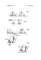
- FIG. 1 is a side view illustrating a system embodying features of the invention and including two cars arranged on a track, one behind the other;
- FIG. 2 is a block diagram of a driving and braking control system embodying features of the invention and used on each of the cars in FIG. 1,
- FIG. 3 is a side view illustrating a system embodying features of the invention and including two cars arranged on a track, one behind the other;
- FIG. 4 is a perspective view of a car and a track together embodying features of the invention.
- FIG. 5 is a perspective view of a car and track together embodying features of the invention.
- the cars l and 2 represent the individual conveyances or transports of a commuter system in which each car commutes automatically without stop between a departure station and a target station.
- the cars l and 2 are just two of many cars, not shown, travelling along the same track. When these cars move at the same speed, it is impossible for one to collide with the other. Consequently, it is possible to drive these cars in train formation, that is with zero distance or close to zero distance between them. As a rule, however, this speed cannot be maintained in all cars. Operational jams may be caused, for example, by the failure of some cars. For this reason, an automatic driving and braking control is provided in each car.
- the car 1 carries a transmitter 4 and a receiver 5.
- the car 2 carries a transmitter 4' and a receiver 5'.
- the transmitters and receivers transmit and receive electromagnetic waves which are symbolically illustrated.
- these electromagnetic waves are light waves.
- the transmitters and receivers transmit sound waves.
- identical antennas are mounted for all of the transmitters and receivers 4,4 and 5,5.
- the preferred antennas are pot shell armature antennas which can be rotated along curves.
- Each transmitter 4 and 4 is associated with only one receiver, namely with the receiver in the car directly following it.
- the transmitters 4,4 and receivers 5,5 in FIG. 1 only those transmitters and receivers, 4' and 5 between the two cars l and 2 are associated with each other.
- the receiver associated with the transmitter 4 of the car 1 is not illustrated.
- the transmitter for the receiver 5' of the car 2 is also not illustrated.
- a common control line 6 connects the transmitter 4 and receiver 5 of the following car 1 in FIG. 1.
- a modulation generator 7 which responds to the speed of the car 1 modulates the transmitting power of the transmitter 4 inversely with the speed of the car and modulates the sensitivity of the receiver 5 directly with the speed of the car.
- the transmitting power attains a maximum and the receiver sensitivity a minimum.
- the transmitting power reaches its minimum and the sensitivity a maximum.
- the modulation generator 7 produces a voltage varying with the speed of the car 1.
- the generator according to an embodiment of the invention, is coupled to and driven by the wheel of the car 1.
- the output voltage of the generator 7 also serves as a control valve for a regulator 8 associated with the drive system (not shown) of the car 1.
- the signal received by the receiver 5 serves as a guide quantity y applied to regulator 8. This guide quantity varies not only with the speed of the receiving end car 1, but also with the speed of the transmitting car 2 and the distance between the two cars 1 and 2. As mentioned above, the power of the transmitter 4 of the transmitting car 2 also varies inversely with its speed.
- the following car 1 is automatically slowed down either by reducing the power applied thereto or by applying brakes. That the guide quantity y is exceeded thus always indicates that the car 1 has a higher speed than the car 2 ahead of it, and the distance between the two cars 1 and 2 is too small for the difference in the speeds. If a collision of one car with the other is to be avoided, the following car must reduce its speed. The cause of the differences in speed may, for example, be the fact that the car 2 has stopped or has reduced its speed.
- the regulator 8 controls the speedup and slowdown of the car 1 so that the car 1 assumes the speed of the car ahead of it. If the speed drops below the guide quantity y, the car is accelerated again. Since the reaction and delay period from the time the beforementioned signal is received to the start of the braking is very short, both cars 1 and 2 as well as those not shown following them can move with practically zero spacing between them, or at least follow each other at extremely short distances.
- additional stationary transmitters and receivers are arranged along the track 3.
- the external transmitters can simulate a car that moves ahead at a reduced speed. It will then automatically reduce the speed of the cars moving along the track.
- Such control of the cars is particularly desirable near switches or branching points, and hence ahead of entrances to and exits from the track.
- the external receivers serve to determine the speed of the individual cars.
- the transmission of signals is not of the wireless transmission type. This applies to the transmission of signals between the cars and the external transmitters and receivers.
- the transmitters and receivers ar coupled to wave guides which are laid along the track. These wave guides form slotted tubular conductors.
- the probes of the cars are introduced into these slotted tubular conductors. Preferably the introduction into the slotted tubular conductors is contact-free. The probes then serve as antennas for the transmitters and receivers.
- ordinary conductors are used instead of the tubular conductors.
- the signals are transmitted inductively between the conductors and the transmitters and receivers of the cars.
- the signals may also be transmitted conductively with brushes.
- the transmitters and receivers operate with light waves.
- Each car is provided with a tail light that serves as the transmitter and a light sensor that serves as the receiver.
- the brightness of the tail light and the sensitivity of the light sensor are controlled in dependence on the speed of the car carrying them.
- the same procedure is used with transmitters and receivers operating with sound waves or ultrasonic waves.
- each car for example two may be mounted on each car. They are coupled to each other over so-called comparators.
- the cars may run on rails.
- the cars constitute conventional motor vehicles moving along the same track or lane. This applies particularly to traffic on limited access highways or Autobahnen.”
- the system and method according to the invention applies to all objects which pass over the same track or path with short distances between them without colliding with each other, for example, objects of a conveyor system for the transfer of goods.
- each receiver 5 and 5 The amplitude of each signal received by each receiver 5 and 5 depends also on the distance between the vehicles 1 and 2, because the power of each signal diminishes with the distance between transmitter and receiver. Thus the vehicles are controlled not only on the basis of the speeds of the vehicles but on the distances beweeen them.
- FIG. 3 illustrates a system which includes second transmitters and receivers located at the sides of the track for the purpose of affecting the operation of the individual cars with outside signals.
- FIG. 4 illustrates a system utilizing a wave guide, specifically a wave guide, having a longitudinal slot with probes from the transmitters and receivers entering the slot. The probes are constructed effectively to maintain communication only between the transmitter of the forward and the receiver of the immediately following car.
- FIG. 5 illustrates a system similar to FIG. 4 except that a conductor extends along the track and the conductor is inductively coupled with the cars l and 2 as well as the remaining cars.
- the method of controlling the speed of objects moving in a single line along a track which comprises sensing the speed of each object, transmitting a signal from each object to the immediately following object, varying the information content of the transmitted signal on the basis of the speed of the transmitting object, sensing the signal from the immediately preceding object, varying the sensing on the basis of the speed of the object sensing the signal, and controlling the speed of the object sensing the signal on the basis of the sensed signal, the steps of varying the information content of the transmitted signal including varying the intensity of the transmitted signal inversely with the speed of the transmitting object to obtain a maximum when the transmitting object stops and to reach a minimum when the transmitting object reaches the maximum speed.
- step of controlling the speed of the object includes comparing the sensed signal with the speed of the object sensing the signal and varying the speed of the object on the basis of the comparison.
- step of controlling the speed of the object includes comparing the sensed signal with the speed of the object sensing the signal and varying the speed of the object on the basis of the comparison.
- step of sensing the signal includes forming a guide quantity y and the step of sensing the speed of each object includes a control quantity x in the sensing object, comparing the quantity x with the quantity y and varying the speed of the sensing object so as to slow down the car when the quantity y is exceeded by the quantity x.
- a system for controlling the speeds of objects travelling along a track in single file comprising transmitter means mounted on each object for transmitting signals to the following object, receiver means mounted on each object for receiving signals from the preceding object, speed responsive means in each of said objects for producing a signal corresponding to the speed of each object along the track, control means in each of said objects responsive to said speed responsive means and coupled to said transmitter means and said receiver means for decreasing the power of the transmitted signals with increasing travel speed of the object and increasing the sensitivity of the receiver means to the received signals with increasing speed of the object, and speed regulating means on each object responsive to said receiver means on that object for controlling the speed of the object having said regulating means.
- said regulating means includes comparator means coupled to said speed responsive means and said receiver means for comparing the output of said receiver means and said speed responsive means and controlling the speed of the vehicle on the basis of the comparison.
- a system as in claim 8 further comprising a plurality of second transmitter means and second receiver means arranged along the track.
- said transmitter means and said receiver means include means for transmitting and receiving electromagnetic waves.
- said regulating means includes comparator means coupled to said speed responsive means and said receiver means for comparing the output of said receiver means and said speed responsive means and controlling the speed of the vehicle on the basis of the comparison.
- each control means controls the transmitting power of said transmitter means inversely with the speed of the object and varying the sensitivity of said receiver means with the speed of each object having said transmitter means and said receiver means.
- said regulating means includes comparator means coupled to said speed responsive means and said receiver means for comparing the output of said receiver means and said speed responsive means and controlling the speed of the vehicle on the basis of the comparison.
- wave guide means form tubular conductors slotted in the longitudinal direction, said transmitter means and said receiver means extending into said tubular conductors and forming probes therein.
Abstract
In the disclosed method and system, vehicles travelling along a track in single file transmit signals to the following vehicles and receive signals from the preceding vehicles. The information content of the transmitted signals varies with the speed of the transmitting vehicle. The information content of the received signals is also modulated by the speed of the receiving vehicle. The speed of the receiving vehicle is varied in dependence upon the signals received.
Description
United States Patent 1 Helmcke et a1.
[ Feb. 5, 1974 METHOD AND MEANS FOR VARYING THE SPEEDS OF VEHICLES MOVING ALONG A TRACK [75] Inventors: Conrad D. Helmcke, Munich; Hans J. Wendt, Buxtehude, both of Germany [73] Assignee: Messerschmitt-Bolkow-Blohm Gesellschaft mit beschrankter Haftung, Munich, Germany [22] Filed: Mar. 14, 1972 [21] Appl. No.: 234,604
[30] Foreign Application Priority Data Mar. 26, 1971 Germany P 21 14 621.4
[52] US. Cl 246/187 C, 246/30, 340/33 [51] Int. Cl B60] 15/20 [58] Field of Search 246/30, 29, 187 C, 167;
340/31, 33, 34, 263; 343/7 A, 7 ED; 180/98 [56] References Cited UNITED STATES PATENTS Spivak 340/33 3,442,347 5/1969 l-lodgson et al. 343/7 ED 801,049 10/1905 Scholz 246/29 R 3,305,682 2/1967 Bolster et al..... 246/187 C 1,747,041 2/1930 Alexanderson 246/187 C Primary ExaminerGerald M. Forlenza Assistant Examiner-George H. Libman Attorney, Agent, or Firm-Totem, McGeady and Stanger ABSTRACT In the disclosed method and system, vehicles travelling along a track in single file transmit signals to the following vehicles and receive signals from the preceding vehicles. The information content of the transmitted signals varies with the speed of the transmitting vehicle. The information content of the received signals is also modulated by the speed of the receiving vehicle. The speed of the receiving vehicle is varied in dependence upon the signals received.
20 Claims, 5 Drawing Figures vmmguraa 51914 3.790.780
ceiver 3 Transmitter METHOD AND MEANS FOR VARYING THE SPEEDS OF VEHICLES MOVING ALONG A TRACK REFERENCE TO COPENDING APPLICATIONS This application relates to the copending application of Conrad Helmcke and Hans J. Wendt, assigned to the same assignee as this application, Ser. No. 234,605, and filed Mar. 14, 1972. The content of that application is included herein as if fully recited herein.
BACKGROUND OF THE INVENTION This invention relates to transport systems and particularly to methods and means for controlling of individual vehicles or objects moving sequentially along a track or path.
The term vehicle is used herein broadly to mean any object, such as a conveyance or car, whose movement along a track or path is controlled.
Commuter and intracity trains are being required to carry increasingly larger numbers of people at substantial speeds. It is possible to meet the demand for high speed, high volume transportation along tracks by densely crowding all the various track sections at the same time. Under these circumstances the safety of the vehicles on the tracks becomes a question of paramount importance. Recently, increasing numbers of so-called linear influence systems have been developed to aid in this problem. These systems control the acceleration, driving, and braking as well as the safety performance of individual cars by continuously monitoring the speeds of the cars. Signals corresponding to values of maximum speed are transmitted between the tracks and the individual cars as driving commands. The expected maximum speed for the track ahead of the car is also indicated by this system. The apparatus for generating the driving commands is arranged at central locations where overall information concerning the traffic over wide regions is available.
Such systems have the advantage over conventional systems with point-of-action light signals, in requiring shorter safety distances at danger points or at points of slow speed. The safety distance that needs to be maintained is only the braking distance determined by monitoring the velocity during the last lowest test speed. Such systems thus considerably reduce the follow time from previous systems.
However, such systems have a number of disadvantages. For example, centralizing the generation of driving commands results in relatively long delay periods between formation and transmission of driving commands. This is inherent in these systems.
Such delay periods can be conveniently disregarded in systems which are attempting 90 second follow times. However, such delays cannot be tolerated with shorter follow times, such as a few seconds, that are planned, for example, for a track carrying individual conveyances (e.g., cabin conveyances, etc.). Successful use of linear influence systems for such individual cars is doubtful, to say the least. All cars on a track attempting to operate with follow times of a few seconds must be monitored. The time available for control of each car is so short that the delays involved in centralized position finding and speed monitoring for generation of driving commands is no longer tolerable.
An object of this invention is to improve such transport systems.
Another object of the invention is to provide an automatic method of speed control, including braking and acceleration control, capable of operating with follow times of but a few seconds.
Another object of the invention is to accomplish the above without the necessity of calculating a distance to be maintained between the vehicles.
BACKGROUND OF THE INVENTION According to a feature of this invention, the above objects are achieved, in whole or in part, by regulating the speed of each vehicle in dependence upon a signal which is transmitted from the immediately preceding vehicle and whose information content varies with the speed of the immediately preceding vehicle, and by modulating the received signal in dependence upon the speed of the vehicle being controlled.
With such a system the driving characteristics or operating characteristics of the immediately preceding vehicle determines the driving characteristics or operating characteristics of the vehicle being controlled. The density of vehicles on the track on which the vehicles move plays no part at all in this control. Thus, centralized-apparatuses for producing driving commands are unnecessary.
Each vehicle or conveyance both transmits and receives a signal that depends upon its speed. Thus, information depending upon the speed of the vehicle itself and the speed of the immediately preceding vehicle is used for control of the driving and braking of each vehicle. Thus, it is impossible to have one vehicle collide with the vehicle ahead. Rather, no distance at all need be maintained between individual vehicles if they have the same weiht and move at the same speed. If, for example, one of the vehicles reduces its speed, the immediately following vehicle is automatically slowed down the same amount. Its braking action results in speed reduction of the vehicle following it.
The term vehicles as used herein is to be understood generally as any moving object controlled by this system.
According to another feature of the invention the intensity of the transmitted signal varies inversely with the speed of the transmitting vehicle. The intensity reaches a maximum when the transmitting vehicle stands still and a minimum at maximum speed. The sensitivity of the receiver in the immediately following vehicle that receives this transmission varies with the speed of the receiving vehicle. Also, preferably, it maintains a minimum sensitivity at standstill and a maximum sensitivity at maximum speed.
According to another feature of the invention, the received signal is compared with a control value that varies with the speed of the receiving vehicle, that is the vehicle that follows the transmitting vehicle. When the control value exceeds the signal, the vehicle is slowed down. As a result, the given distance is automatically maintained between the vehicles.
The intensity of the received signal and the sensitivity of the associated receiving device can be regulated down to zero, even a zero distance is possible between the vehicles, both at standstill and at maximum speed.
According to another feature of the invention, the transmitting and receiving powers are selected for all the transmitters and receivers so that the respective receivers can receive signals only from the vehicle directly ahead of the vehicle carrying the receiver, or to respond to such signals. 7
According to another feature of the invention, each vehicle is equipped with a transmitter and receiver whose transmitting and receiving powers depend upon the speed of the vehicle carrying them.
According to another feature of the invention, these transmitters and receivers operate with electromagnetic waves.
According to yet another feature of the invention, they transmit and receive sound waves.
According to yet another feature of the invention, the transmission and reception is accomplished by other than wireless transmission and utilizes the track itself.
These and other features of the invention are pointed out in the claims. Other objects and advantages of the invention will become known from the following detailed description when read in light of the accompanying drawings.
BRIEF DESCRIPTION OF THE DRAWINGS In the drawings:
FIG. 1 is a side view illustrating a system embodying features of the invention and including two cars arranged on a track, one behind the other;
FIG. 2 is a block diagram of a driving and braking control system embodying features of the invention and used on each of the cars in FIG. 1,
FIG. 3 is a side view illustrating a system embodying features of the invention and including two cars arranged on a track, one behind the other;
FIG. 4 is a perspective view of a car and a track together embodying features of the invention; and
FIG. 5 is a perspective view of a car and track together embodying features of the invention.
DESCRIPTION OF PREFERRED EMBODIMENTS In the following description it should be noted that the control illustrated in FIG. 2 is provided in each of the cars, although only the apparatus used in one car is illustrated.
In FIG. 1, two cars 1 and 2 travel one behind the other in single file along a track 3. The cars l and 2 represent the individual conveyances or transports of a commuter system in which each car commutes automatically without stop between a departure station and a target station. The cars l and 2 are just two of many cars, not shown, travelling along the same track. When these cars move at the same speed, it is impossible for one to collide with the other. Consequently, it is possible to drive these cars in train formation, that is with zero distance or close to zero distance between them. As a rule, however, this speed cannot be maintained in all cars. Operational jams may be caused, for example, by the failure of some cars. For this reason, an automatic driving and braking control is provided in each car.
In FIG. 1 the car 1 carries a transmitter 4 and a receiver 5. The car 2 carries a transmitter 4' and a receiver 5'. According to one embodiment of the invention, the transmitters and receivers transmit and receive electromagnetic waves which are symbolically illustrated. According to another embodiment of the invention, these electromagnetic waves are light waves. According to another embodiment of the invention the transmitters and receivers transmit sound waves.
According to a preferred embodiment of the invention, identical antennas are mounted for all of the transmitters and receivers 4,4 and 5,5. The preferred antennas are pot shell armature antennas which can be rotated along curves.
Each transmitter 4 and 4 is associated with only one receiver, namely with the receiver in the car directly following it. Of the transmitters 4,4 and receivers 5,5 in FIG. 1, only those transmitters and receivers, 4' and 5 between the two cars l and 2 are associated with each other. The receiver associated with the transmitter 4 of the car 1 is not illustrated. The transmitter for the receiver 5' of the car 2 is also not illustrated.
In FIG. 2, a common control line 6 connects the transmitter 4 and receiver 5 of the following car 1 in FIG. 1. A modulation generator 7 which responds to the speed of the car 1 modulates the transmitting power of the transmitter 4 inversely with the speed of the car and modulates the sensitivity of the receiver 5 directly with the speed of the car. Thus, when the car 1 stands still, the transmitting power attains a maximum and the receiver sensitivity a minimum. When car 1 travels at its maximum speed, the transmitting power reaches its minimum and the sensitivity a maximum. The modulation generator 7 produces a voltage varying with the speed of the car 1. The generator, according to an embodiment of the invention, is coupled to and driven by the wheel of the car 1.
The output voltage of the generator 7 also serves as a control valve for a regulator 8 associated with the drive system (not shown) of the car 1. The signal received by the receiver 5 serves as a guide quantity y applied to regulator 8. This guide quantity varies not only with the speed of the receiving end car 1, but also with the speed of the transmitting car 2 and the distance between the two cars 1 and 2. As mentioned above, the power of the transmitter 4 of the transmitting car 2 also varies inversely with its speed.
If the comparison of the control value x with the guide value y shows that the guide value y has been exceeded, the following car 1 is automatically slowed down either by reducing the power applied thereto or by applying brakes. That the guide quantity y is exceeded thus always indicates that the car 1 has a higher speed than the car 2 ahead of it, and the distance between the two cars 1 and 2 is too small for the difference in the speeds. If a collision of one car with the other is to be avoided, the following car must reduce its speed. The cause of the differences in speed may, for example, be the fact that the car 2 has stopped or has reduced its speed.
The regulator 8 controls the speedup and slowdown of the car 1 so that the car 1 assumes the speed of the car ahead of it. If the speed drops below the guide quantity y, the car is accelerated again. Since the reaction and delay period from the time the beforementioned signal is received to the start of the braking is very short, both cars 1 and 2 as well as those not shown following them can move with practically zero spacing between them, or at least follow each other at extremely short distances.
According to another embodiment of the invention, apart from the above-mentioned transmitters 4 and 4 and receivers 5 and 5 additional stationary transmitters and receivers are arranged along the track 3. The external transmitters can simulate a car that moves ahead at a reduced speed. It will then automatically reduce the speed of the cars moving along the track. Such control of the cars is particularly desirable near switches or branching points, and hence ahead of entrances to and exits from the track. The external receivers serve to determine the speed of the individual cars.
According to another embodiment of the invention, the transmission of signals is not of the wireless transmission type. This applies to the transmission of signals between the cars and the external transmitters and receivers. According to this embodiment, the transmitters and receivers ar coupled to wave guides which are laid along the track. These wave guides form slotted tubular conductors. The probes of the cars are introduced into these slotted tubular conductors. Preferably the introduction into the slotted tubular conductors is contact-free. The probes then serve as antennas for the transmitters and receivers.
According to another embodiment of the invention, ordinary conductors are used instead of the tubular conductors. In this case the signals are transmitted inductively between the conductors and the transmitters and receivers of the cars. The signals may also be transmitted conductively with brushes.
According to another embodiment of the invention, the transmitters and receivers operate with light waves. Each car is provided with a tail light that serves as the transmitter and a light sensor that serves as the receiver. The brightness of the tail light and the sensitivity of the light sensor are controlled in dependence on the speed of the car carrying them.
According to another embodiment of the invention, the same procedure is used with transmitters and receivers operating with sound waves or ultrasonic waves.
For safety reasons, according to yet another embodiment of the invention, several transmitters and receivers are mounted on each car, for example two may be mounted on each car. They are coupled to each other over so-called comparators. The cars may run on rails. However, according to another embodiment of the invention, the cars constitute conventional motor vehicles moving along the same track or lane. This applies particularly to traffic on limited access highways or Autobahnen." The system and method according to the invention applies to all objects which pass over the same track or path with short distances between them without colliding with each other, for example, objects of a conveyor system for the transfer of goods.
The amplitude of each signal received by each receiver 5 and 5 depends also on the distance between the vehicles 1 and 2, because the power of each signal diminishes with the distance between transmitter and receiver. Thus the vehicles are controlled not only on the basis of the speeds of the vehicles but on the distances beweeen them.
While embodiments of the invention have been described in detail it will be obvious to those skilled in the art that the invention may be embodied otherwise.
FIG. 3 illustrates a system which includes second transmitters and receivers located at the sides of the track for the purpose of affecting the operation of the individual cars with outside signals. FIG. 4 illustrates a system utilizing a wave guide, specifically a wave guide, having a longitudinal slot with probes from the transmitters and receivers entering the slot. The probes are constructed effectively to maintain communication only between the transmitter of the forward and the receiver of the immediately following car. FIG. 5 illustrates a system similar to FIG. 4 except that a conductor extends along the track and the conductor is inductively coupled with the cars l and 2 as well as the remaining cars.
What is claimed is:
l. The method of controlling the speed of objects moving in a single line along a track, which comprises sensing the speed of each object, transmitting a signal from each object to the immediately following object, varying the information content of the transmitted signal on the basis of the speed of the transmitting object, sensing the signal from the immediately preceding object, varying the sensing on the basis of the speed of the object sensing the signal, and controlling the speed of the object sensing the signal on the basis of the sensed signal, the steps of varying the information content of the transmitted signal including varying the intensity of the transmitted signal inversely with the speed of the transmitting object to obtain a maximum when the transmitting object stops and to reach a minimum when the transmitting object reaches the maximum speed.
2. The method as in claim 1, wherein the sensitivity of the sensing is varied with the speed of the object sensing the signal.
3. The method as in claim 1, wherein the sensing is performed so as to create maximum sensitivity when the object sensing the signal reaches a maximum speed and minimum sensitivity when the sensing object stops.
4. The method as in claim 1, wherein the step of controlling the speed of the object includes comparing the sensed signal with the speed of the object sensing the signal and varying the speed of the object on the basis of the comparison. 1
5. The method as in claim 2, wherein the step of controlling the speed of the object includes comparing the sensed signal with the speed of the object sensing the signal and varying the speed of the object on the basis of the comparison.
6. The method as in claim 3, wherein the step of sensing the signal includes forming a guide quantity y and the step of sensing the speed of each object includes a control quantity x in the sensing object, comparing the quantity x with the quantity y and varying the speed of the sensing object so as to slow down the car when the quantity y is exceeded by the quantity x.
7. The method as in claim 1, wherein the method is used in individual cars travelling along the track.
8. A system for controlling the speeds of objects travelling along a track in single file, comprising transmitter means mounted on each object for transmitting signals to the following object, receiver means mounted on each object for receiving signals from the preceding object, speed responsive means in each of said objects for producing a signal corresponding to the speed of each object along the track, control means in each of said objects responsive to said speed responsive means and coupled to said transmitter means and said receiver means for decreasing the power of the transmitted signals with increasing travel speed of the object and increasing the sensitivity of the receiver means to the received signals with increasing speed of the object, and speed regulating means on each object responsive to said receiver means on that object for controlling the speed of the object having said regulating means.
9. A system as in claim 8, wherein said regulating means includes comparator means coupled to said speed responsive means and said receiver means for comparing the output of said receiver means and said speed responsive means and controlling the speed of the vehicle on the basis of the comparison.
10. A system as in claim 8 further comprising a plurality of second transmitter means and second receiver means arranged along the track.
11. A system as in claim 13, wherein said transmitter means and said receiver means include means for transmitting and receiving electromagnetic waves.
12. A system as in claim 11, wherein said regulating means includes comparator means coupled to said speed responsive means and said receiver means for comparing the output of said receiver means and said speed responsive means and controlling the speed of the vehicle on the basis of the comparison.
13. A system as in claim 8, wherein said transmitter means and receiver means transmit and receive light waves.
14. A system as in claim 10, wherein said transmitter means and receiver means transmit and receive light waves.
15. A system as in claim 8, wherein said transmitter means and receiver means transmit and receive sound waves.
16. A system as in claim 10, wherein said transmitter means and receiver means transmit and receive sound waves.
17. A system as in claim 8, further comprising wave guide means extending along said track and coupling said transmitter means to each other and receiver means.
18. A system as in claim 17, wherein each control means controls the transmitting power of said transmitter means inversely with the speed of the object and varying the sensitivity of said receiver means with the speed of each object having said transmitter means and said receiver means.
19. A system as in claim 17, wherein said regulating means includes comparator means coupled to said speed responsive means and said receiver means for comparing the output of said receiver means and said speed responsive means and controlling the speed of the vehicle on the basis of the comparison.
20. A system as in claim 17, wherein said wave guide means form tubular conductors slotted in the longitudinal direction, said transmitter means and said receiver means extending into said tubular conductors and forming probes therein.
Claims (20)
1. The method of controlling the speed of objects moving in a single line along a track, which comprises sensing the speed of each object, transmitting a signal from each object to the immediately following object, varying the information content of the transmitted signal on the basis of the speed of the transmitting object, sensing the signal from the immediately preceding object, varying the sensing on the basis of the speed of the object sensing the signal, and controlling the speed of the object sensing the signal on the basis of the sensed signal, the steps of varying the information content of the transmitted signal including varying the intensity of the transmitted signal inversely with the speed of the transmitting object to obtain a maximum when the transmitting object stops and to reach a minimum when the transmitting object reaches the maximum speed.
2. The method as in claim 1, wherein the sensitivity of the sensing is varied with the speed of the object sensing the signal.
3. The method as in claim 1, wherein the sensing is performed so as to create maximum sensitivity when the object sensing the signal reaches a maximum speed and minimum sensitivity when the sensing object stops.
4. The method as in claim 1, wherein the step of controlling the speed of the object includes comparing the sensed signal with the speed of the object sensing the signal and varying the speed of the object on the basis of the comparison.
5. The method as in claim 2, wherein the step of controlling the speed of the object includes comparing the sensed signal with the speed of the object sensing the signal and varying the speed of the object on the basis of the comparisoN.
6. The method as in claim 3, wherein the step of sensing the signal includes forming a guide quantity y and the step of sensing the speed of each object includes a control quantity x in the sensing object, comparing the quantity x with the quantity y and varying the speed of the sensing object so as to slow down the car when the quantity y is exceeded by the quantity x.
7. The method as in claim 1, wherein the method is used in individual cars travelling along the track.
8. A system for controlling the speeds of objects travelling along a track in single file, comprising transmitter means mounted on each object for transmitting signals to the following object, receiver means mounted on each object for receiving signals from the preceding object, speed responsive means in each of said objects for producing a signal corresponding to the speed of each object along the track, control means in each of said objects responsive to said speed responsive means and coupled to said transmitter means and said receiver means for decreasing the power of the transmitted signals with increasing travel speed of the object and increasing the sensitivity of the receiver means to the received signals with increasing speed of the object, and speed regulating means on each object responsive to said receiver means on that object for controlling the speed of the object having said regulating means.
9. A system as in claim 8, wherein said regulating means includes comparator means coupled to said speed responsive means and said receiver means for comparing the output of said receiver means and said speed responsive means and controlling the speed of the vehicle on the basis of the comparison.
10. A system as in claim 8 further comprising a plurality of second transmitter means and second receiver means arranged along the track.
11. A system as in claim 13, wherein said transmitter means and said receiver means include means for transmitting and receiving electromagnetic waves.
12. A system as in claim 11, wherein said regulating means includes comparator means coupled to said speed responsive means and said receiver means for comparing the output of said receiver means and said speed responsive means and controlling the speed of the vehicle on the basis of the comparison.
13. A system as in claim 8, wherein said transmitter means and receiver means transmit and receive light waves.
14. A system as in claim 10, wherein said transmitter means and receiver means transmit and receive light waves.
15. A system as in claim 8, wherein said transmitter means and receiver means transmit and receive sound waves.
16. A system as in claim 10, wherein said transmitter means and receiver means transmit and receive sound waves.
17. A system as in claim 8, further comprising wave guide means extending along said track and coupling said transmitter means to each other and receiver means.
18. A system as in claim 17, wherein each control means controls the transmitting power of said transmitter means inversely with the speed of the object and varying the sensitivity of said receiver means with the speed of each object having said transmitter means and said receiver means.
19. A system as in claim 17, wherein said regulating means includes comparator means coupled to said speed responsive means and said receiver means for comparing the output of said receiver means and said speed responsive means and controlling the speed of the vehicle on the basis of the comparison.
20. A system as in claim 17, wherein said wave guide means form tubular conductors slotted in the longitudinal direction, said transmitter means and said receiver means extending into said tubular conductors and forming probes therein.
Applications Claiming Priority (1)
| Application Number | Priority Date | Filing Date | Title |
|---|---|---|---|
| DE2114621A DE2114621C3 (en) | 1971-03-26 | 1971-03-26 | Process for the automatic, distance-secured braking and travel control of vehicles on the same track or lane |
Publications (1)
| Publication Number | Publication Date |
|---|---|
| US3790780A true US3790780A (en) | 1974-02-05 |
Family
ID=5802798
Family Applications (1)
| Application Number | Title | Priority Date | Filing Date |
|---|---|---|---|
| US00234604A Expired - Lifetime US3790780A (en) | 1971-03-26 | 1972-03-14 | Method and means for varying the speeds of vehicles moving along a track |
Country Status (10)
| Country | Link |
|---|---|
| US (1) | US3790780A (en) |
| JP (1) | JPS5648335B1 (en) |
| AT (1) | AT319104B (en) |
| DD (1) | DD95597A5 (en) |
| DE (1) | DE2114621C3 (en) |
| FR (1) | FR2131433A5 (en) |
| GB (1) | GB1370165A (en) |
| IT (1) | IT950452B (en) |
| NL (1) | NL7203424A (en) |
| SE (1) | SE382952B (en) |
Cited By (33)
| Publication number | Priority date | Publication date | Assignee | Title |
|---|---|---|---|---|
| US3941201A (en) * | 1972-08-01 | 1976-03-02 | Messerschmitt-Bolkow-Blohm Gmbh | Traffic merging method and means |
| US4085913A (en) * | 1977-01-12 | 1978-04-25 | Chang Chen Kun | Device for preventing collision of trains |
| US4335432A (en) * | 1980-01-28 | 1982-06-15 | United States Of America | Optimal vehicle following control system |
| FR2521080A1 (en) * | 1982-02-10 | 1983-08-12 | Mitsubishi Electric Corp | CONSTANT SPEED DRIVING DEVICE FOR A MOTOR VEHICLE |
| US4473787A (en) * | 1980-11-14 | 1984-09-25 | Inventio Ag | Equipment for maintaining the spacing of track-bound vehicles |
| EP0146851A2 (en) * | 1983-12-06 | 1985-07-03 | Nissan Motor Co., Ltd. | System and method for automatically controlling vehicle speed |
| US4578665A (en) * | 1982-04-28 | 1986-03-25 | Yang Tai Her | Remote controlled surveillance train car |
| FR2598375A1 (en) * | 1986-05-07 | 1987-11-13 | Spitz Martin | Speed control for railway track and automatic driving of trains |
| US4723737A (en) * | 1984-10-18 | 1988-02-09 | Matra Transport | Process and device for transmitting data between vehicles moving over a track |
| US4864306A (en) * | 1986-06-23 | 1989-09-05 | Wiita Floyd L | Railway anticollision apparatus and method |
| EP0347242A2 (en) * | 1988-06-17 | 1989-12-20 | Yng-Lang Lin | Collison avoidance system |
| US4891624A (en) * | 1987-06-12 | 1990-01-02 | Stanley Electric Co., Ltd. | Rearward vehicle obstruction detector using modulated light from the brake light elements |
| US5037045A (en) * | 1989-01-19 | 1991-08-06 | Nakanishi Metal Works Co., Ltd. | Self-propelled carrier conveyor having carrier distancing control |
| US5134393A (en) * | 1990-04-02 | 1992-07-28 | Henson H Keith | Traffic control system |
| US5295551A (en) * | 1986-03-06 | 1994-03-22 | Josef Sukonick | System for the cooperative driving of two or more vehicles |
| US5351919A (en) * | 1993-03-29 | 1994-10-04 | Primetech Electroniques Inc. | Trainline communication link using radio frequency signal |
| US5754123A (en) * | 1996-05-06 | 1998-05-19 | Ford Motor Company | Hybrid ultrasonic and radar based backup aid |
| WO1998024673A1 (en) * | 1996-12-02 | 1998-06-11 | Tae Jin Park | Personal rapid transit system utilizing both course reservation and branch stop technologies |
| US5902341A (en) * | 1996-10-30 | 1999-05-11 | Scientific-Atlanta, Inc. | Method and apparatus to automatically generate a train manifest |
| EP1118573A1 (en) * | 2000-01-20 | 2001-07-25 | Inventio Ag | Method for providing collision safety in a transport system with vehicles travelling on the same lane |
| WO2002014133A1 (en) * | 2000-08-16 | 2002-02-21 | Eisenmann Maschinenbau Kg | Electric overhead conveyer |
| US6369720B1 (en) * | 1998-05-22 | 2002-04-09 | Alcatel | Method for information transmission of vehicle data and traffic information system |
| EP1174319A3 (en) * | 2000-07-17 | 2002-10-09 | Friedrich-Karl Dr. Wefelmeier | Deceleration system for motor vehicle |
| US20050165537A1 (en) * | 2003-12-17 | 2005-07-28 | Dort David B. | Externally activated non-negative acceleration system |
| US20070242338A1 (en) * | 2006-04-17 | 2007-10-18 | James Roy Bradley | System and Method for Vehicular Communications |
| US20070242337A1 (en) * | 2006-04-17 | 2007-10-18 | Bradley James R | System and Method for Vehicular Communications |
| US20070242339A1 (en) * | 2006-04-17 | 2007-10-18 | James Roy Bradley | System and Method for Vehicular Communications |
| US20080122606A1 (en) * | 2006-04-17 | 2008-05-29 | James Roy Bradley | System and Method for Vehicular Communications |
| US20080122607A1 (en) * | 2006-04-17 | 2008-05-29 | James Roy Bradley | System and Method for Vehicular Communications |
| EP2335997A1 (en) * | 2009-12-16 | 2011-06-22 | Eisenmann AG | Conveying system |
| US20120083983A1 (en) * | 2009-06-19 | 2012-04-05 | Bosch Corporation | Vehicular braking control device |
| US8483895B1 (en) | 2009-02-25 | 2013-07-09 | James J. Beregi | Transportation system, system components and process |
| WO2019201798A1 (en) * | 2018-04-20 | 2019-10-24 | Eisenmann Se | Conveyor system and method for controlling such a conveyor system |
Families Citing this family (16)
| Publication number | Priority date | Publication date | Assignee | Title |
|---|---|---|---|---|
| FR2240492A1 (en) * | 1973-08-08 | 1975-03-07 | Gendrot Andre | Vehicle accident signalling system - emitts radio signal to warn approaching vehicles |
| DE2547011C3 (en) * | 1975-10-21 | 1981-06-11 | Messerschmitt-Bölkow-Blohm GmbH, 8000 München | High frequency ribbon cable |
| US4108269A (en) * | 1976-08-31 | 1978-08-22 | Kabushiki Kaisha Komatsu Seisakusho | No-man control system for working vehicles |
| DE2922111C2 (en) * | 1979-05-31 | 1982-08-26 | Messerschmitt-Bölkow-Blohm GmbH, 8000 München | Method for securing track-bound vehicles against vehicles in the same lane |
| FR2558266A1 (en) * | 1983-10-03 | 1985-07-19 | Rambaud Guy | SELECTIVE OBSTACLE DETECTOR DEVICE FOR VEHICLE |
| FR2565925B1 (en) * | 1984-06-15 | 1988-02-19 | Sud Ouest Travaux | SAFETY SYSTEM FOR MOBILE VEHICLES ON THE SAME TRACE |
| FR2586845B1 (en) * | 1985-08-27 | 1987-10-23 | Bernard Legros | ANTI-COLLISION SECURITY SYSTEM FOR MOVING AND / OR STOPPING MOBILES. |
| US4644237A (en) * | 1985-10-17 | 1987-02-17 | International Business Machines Corp. | Collision avoidance system |
| DE3634302A1 (en) * | 1986-10-08 | 1988-04-21 | Porsche Ag | DISTANCE CONTROL SYSTEM FOR MOTOR VEHICLES |
| FR2624454B1 (en) * | 1987-07-27 | 1991-08-23 | Neiman Sa | DANGER SIGNALING DEVICE ON BOARD OF A MOTOR VEHICLE |
| FR2655755A1 (en) * | 1989-12-13 | 1991-06-14 | Collot Jean Francois | Device for repeating driving events and for signalling an accident from vehicle to vehicle |
| DE4108671A1 (en) * | 1991-03-16 | 1992-09-17 | Standard Elektrik Lorenz Ag | METHOD FOR CONTROLLING THE SPEEDS OF FOLLOWING RAIL VEHICLES |
| DE102004032015A1 (en) * | 2004-07-01 | 2006-01-26 | Siemens Ag | Rail vehicle with an overstretch track for data and / or commands |
| DE102006019495A1 (en) * | 2006-04-26 | 2007-10-31 | Siemens Ag | Warning signal sending device for e.g. camper, has processing device for processing output signal provided by signal receiver, and signal generator for sending warning signal on basis of output signal processed by processing device |
| DE102013006687B4 (en) | 2013-04-18 | 2019-05-23 | Audi Ag | Light control in the "Roadtrain" |
| US20190112697A1 (en) | 2016-03-31 | 2019-04-18 | Jfe Steel Corporation | Electrical steel sheet and method of producing the same |
Citations (5)
| Publication number | Priority date | Publication date | Assignee | Title |
|---|---|---|---|---|
| US801049A (en) * | 1905-04-27 | 1905-10-03 | Karl Scholz | Railway signaling system. |
| US1747041A (en) * | 1928-10-27 | 1930-02-11 | Gen Electric | Speed-indicating system |
| US3305682A (en) * | 1963-07-26 | 1967-02-21 | Gen Electric | Ranging system |
| US3442347A (en) * | 1965-03-31 | 1969-05-06 | Robert W Hodgson | Safe trailing distance maintenance system for a trailing carrier vehicle |
| US3662328A (en) * | 1969-04-30 | 1972-05-09 | David Spivak | Apparatus for determining the proximity of moving vehicles |
Family Cites Families (1)
| Publication number | Priority date | Publication date | Assignee | Title |
|---|---|---|---|---|
| BE788683R (en) * | 1971-09-13 | 1973-03-12 | Westinghouse Electric Corp | NUCLEAR REACTOR WITH FUEL RECHARGE |
-
1971
- 1971-03-26 DE DE2114621A patent/DE2114621C3/en not_active Expired
-
1972
- 1972-03-14 FR FR7208871A patent/FR2131433A5/fr not_active Expired
- 1972-03-14 GB GB1178472A patent/GB1370165A/en not_active Expired
- 1972-03-14 US US00234604A patent/US3790780A/en not_active Expired - Lifetime
- 1972-03-15 NL NL7203424A patent/NL7203424A/xx not_active Application Discontinuation
- 1972-03-22 IT IT22201/72A patent/IT950452B/en active
- 1972-03-24 JP JP2904972A patent/JPS5648335B1/ja active Pending
- 1972-03-24 SE SE7203811A patent/SE382952B/en unknown
- 1972-03-24 AT AT256072A patent/AT319104B/en not_active IP Right Cessation
- 1972-03-24 DD DD161807A patent/DD95597A5/xx unknown
Patent Citations (5)
| Publication number | Priority date | Publication date | Assignee | Title |
|---|---|---|---|---|
| US801049A (en) * | 1905-04-27 | 1905-10-03 | Karl Scholz | Railway signaling system. |
| US1747041A (en) * | 1928-10-27 | 1930-02-11 | Gen Electric | Speed-indicating system |
| US3305682A (en) * | 1963-07-26 | 1967-02-21 | Gen Electric | Ranging system |
| US3442347A (en) * | 1965-03-31 | 1969-05-06 | Robert W Hodgson | Safe trailing distance maintenance system for a trailing carrier vehicle |
| US3662328A (en) * | 1969-04-30 | 1972-05-09 | David Spivak | Apparatus for determining the proximity of moving vehicles |
Cited By (40)
| Publication number | Priority date | Publication date | Assignee | Title |
|---|---|---|---|---|
| US3941201A (en) * | 1972-08-01 | 1976-03-02 | Messerschmitt-Bolkow-Blohm Gmbh | Traffic merging method and means |
| US4085913A (en) * | 1977-01-12 | 1978-04-25 | Chang Chen Kun | Device for preventing collision of trains |
| US4335432A (en) * | 1980-01-28 | 1982-06-15 | United States Of America | Optimal vehicle following control system |
| US4473787A (en) * | 1980-11-14 | 1984-09-25 | Inventio Ag | Equipment for maintaining the spacing of track-bound vehicles |
| FR2521080A1 (en) * | 1982-02-10 | 1983-08-12 | Mitsubishi Electric Corp | CONSTANT SPEED DRIVING DEVICE FOR A MOTOR VEHICLE |
| US4578665A (en) * | 1982-04-28 | 1986-03-25 | Yang Tai Her | Remote controlled surveillance train car |
| EP0146851A2 (en) * | 1983-12-06 | 1985-07-03 | Nissan Motor Co., Ltd. | System and method for automatically controlling vehicle speed |
| EP0146851A3 (en) * | 1983-12-06 | 1986-01-29 | Nissan Motor Co., Ltd. | System and method for automatically controlling vehicle speed |
| US4670845A (en) * | 1983-12-06 | 1987-06-02 | Nissan Motor Company, Limited | System and method for automatically controlling vehicle speed |
| US4723737A (en) * | 1984-10-18 | 1988-02-09 | Matra Transport | Process and device for transmitting data between vehicles moving over a track |
| US5295551A (en) * | 1986-03-06 | 1994-03-22 | Josef Sukonick | System for the cooperative driving of two or more vehicles |
| FR2598375A1 (en) * | 1986-05-07 | 1987-11-13 | Spitz Martin | Speed control for railway track and automatic driving of trains |
| US4864306A (en) * | 1986-06-23 | 1989-09-05 | Wiita Floyd L | Railway anticollision apparatus and method |
| US4891624A (en) * | 1987-06-12 | 1990-01-02 | Stanley Electric Co., Ltd. | Rearward vehicle obstruction detector using modulated light from the brake light elements |
| EP0347242A2 (en) * | 1988-06-17 | 1989-12-20 | Yng-Lang Lin | Collison avoidance system |
| EP0347242A3 (en) * | 1988-06-17 | 1990-11-07 | Yng-Lang Lin | Collison avoidance system |
| US5037045A (en) * | 1989-01-19 | 1991-08-06 | Nakanishi Metal Works Co., Ltd. | Self-propelled carrier conveyor having carrier distancing control |
| US5134393A (en) * | 1990-04-02 | 1992-07-28 | Henson H Keith | Traffic control system |
| US5351919A (en) * | 1993-03-29 | 1994-10-04 | Primetech Electroniques Inc. | Trainline communication link using radio frequency signal |
| US5435505A (en) * | 1993-03-29 | 1995-07-25 | Primetech Electroniques Inc. | Electronic communications radio frequency coupler for multi-car vehicle |
| US5754123A (en) * | 1996-05-06 | 1998-05-19 | Ford Motor Company | Hybrid ultrasonic and radar based backup aid |
| US5902341A (en) * | 1996-10-30 | 1999-05-11 | Scientific-Atlanta, Inc. | Method and apparatus to automatically generate a train manifest |
| WO1998024673A1 (en) * | 1996-12-02 | 1998-06-11 | Tae Jin Park | Personal rapid transit system utilizing both course reservation and branch stop technologies |
| US6318274B1 (en) * | 1996-12-02 | 2001-11-20 | Tae Jin Park | Guideway transit system |
| US6369720B1 (en) * | 1998-05-22 | 2002-04-09 | Alcatel | Method for information transmission of vehicle data and traffic information system |
| EP1118573A1 (en) * | 2000-01-20 | 2001-07-25 | Inventio Ag | Method for providing collision safety in a transport system with vehicles travelling on the same lane |
| EP1174319A3 (en) * | 2000-07-17 | 2002-10-09 | Friedrich-Karl Dr. Wefelmeier | Deceleration system for motor vehicle |
| WO2002014133A1 (en) * | 2000-08-16 | 2002-02-21 | Eisenmann Maschinenbau Kg | Electric overhead conveyer |
| US7151992B2 (en) * | 2003-12-17 | 2006-12-19 | Vrbia, Inc. | Externally activated non-negative acceleration system |
| US20050165537A1 (en) * | 2003-12-17 | 2005-07-28 | Dort David B. | Externally activated non-negative acceleration system |
| US20070242338A1 (en) * | 2006-04-17 | 2007-10-18 | James Roy Bradley | System and Method for Vehicular Communications |
| US20070242337A1 (en) * | 2006-04-17 | 2007-10-18 | Bradley James R | System and Method for Vehicular Communications |
| US20070242339A1 (en) * | 2006-04-17 | 2007-10-18 | James Roy Bradley | System and Method for Vehicular Communications |
| US20080122606A1 (en) * | 2006-04-17 | 2008-05-29 | James Roy Bradley | System and Method for Vehicular Communications |
| US20080122607A1 (en) * | 2006-04-17 | 2008-05-29 | James Roy Bradley | System and Method for Vehicular Communications |
| US7961086B2 (en) | 2006-04-17 | 2011-06-14 | James Roy Bradley | System and method for vehicular communications |
| US8483895B1 (en) | 2009-02-25 | 2013-07-09 | James J. Beregi | Transportation system, system components and process |
| US20120083983A1 (en) * | 2009-06-19 | 2012-04-05 | Bosch Corporation | Vehicular braking control device |
| EP2335997A1 (en) * | 2009-12-16 | 2011-06-22 | Eisenmann AG | Conveying system |
| WO2019201798A1 (en) * | 2018-04-20 | 2019-10-24 | Eisenmann Se | Conveyor system and method for controlling such a conveyor system |
Also Published As
| Publication number | Publication date |
|---|---|
| FR2131433A5 (en) | 1972-11-10 |
| DE2114621B2 (en) | 1974-06-06 |
| AT319104B (en) | 1974-12-10 |
| JPS5648335B1 (en) | 1981-11-14 |
| DE2114621C3 (en) | 1979-06-21 |
| IT950452B (en) | 1973-06-20 |
| NL7203424A (en) | 1972-09-28 |
| DE2114621A1 (en) | 1972-09-28 |
| DD95597A5 (en) | 1973-02-12 |
| SE382952B (en) | 1976-02-23 |
| GB1370165A (en) | 1974-10-16 |
Similar Documents
| Publication | Publication Date | Title |
|---|---|---|
| US3790780A (en) | Method and means for varying the speeds of vehicles moving along a track | |
| US4932617A (en) | System for transmitting broadband data and/or instructions between a moving element and a control station | |
| JP3234925B2 (en) | Train control device | |
| US6505103B1 (en) | Method and apparatus for controlling remote locomotive operation | |
| US3941201A (en) | Traffic merging method and means | |
| CN1137993A (en) | Method for establishing mutual contact within train and device for implementing the method | |
| US3796871A (en) | Methods and means for merging two lanes of traffic | |
| US3774025A (en) | Vehicle control system | |
| US11458999B2 (en) | On-board control apparatus and platform-door control system | |
| JP3342979B2 (en) | Train security control system | |
| EP0030121A1 (en) | Transit vehicle control apparatus and method | |
| CN113428191B (en) | Ground active accurate train parking method and system | |
| JPS63164636A (en) | Wide band data and/or instruction transmission system between movable element and control station | |
| KR19980083717A (en) | Automatic train control device and method | |
| JP3433958B2 (en) | Mobile control device | |
| JPH11134600A (en) | Traveling controller of automatic traveling vehicle | |
| JPH11129901A (en) | Punning support device | |
| JPH05236613A (en) | Operating method for rolling stock | |
| JPH10100737A (en) | Automatic drive vehicle | |
| JPH07251739A (en) | Rolling stock running device | |
| JP2002330502A (en) | On-vehicle main-body type automatic train control device | |
| JPH0398406A (en) | Automatic operation controller for train | |
| JP3255968B2 (en) | Route control device | |
| JP3010770B2 (en) | Load transfer equipment | |
| JP3347908B2 (en) | Automatic train stop device |