US3793701A - Process for the connection by setting of collectors on water-boxes of heat exchangers - Google Patents
Process for the connection by setting of collectors on water-boxes of heat exchangers Download PDFInfo
- Publication number
- US3793701A US3793701A US00094237A US3793701DA US3793701A US 3793701 A US3793701 A US 3793701A US 00094237 A US00094237 A US 00094237A US 3793701D A US3793701D A US 3793701DA US 3793701 A US3793701 A US 3793701A
- Authority
- US
- United States
- Prior art keywords
- water
- belt
- flanges
- collar
- collector
- Prior art date
- Legal status (The legal status is an assumption and is not a legal conclusion. Google has not performed a legal analysis and makes no representation as to the accuracy of the status listed.)
- Expired - Lifetime
Links
Images


Classifications
-
- F—MECHANICAL ENGINEERING; LIGHTING; HEATING; WEAPONS; BLASTING
- F28—HEAT EXCHANGE IN GENERAL
- F28F—DETAILS OF HEAT-EXCHANGE AND HEAT-TRANSFER APPARATUS, OF GENERAL APPLICATION
- F28F9/00—Casings; Header boxes; Auxiliary supports for elements; Auxiliary members within casings
- F28F9/02—Header boxes; End plates
- F28F9/0219—Arrangements for sealing end plates into casing or header box; Header box sub-elements
- F28F9/0224—Header boxes formed by sealing end plates into covers
- F28F9/0226—Header boxes formed by sealing end plates into covers with resilient gaskets
-
- B—PERFORMING OPERATIONS; TRANSPORTING
- B21—MECHANICAL METAL-WORKING WITHOUT ESSENTIALLY REMOVING MATERIAL; PUNCHING METAL
- B21D—WORKING OR PROCESSING OF SHEET METAL OR METAL TUBES, RODS OR PROFILES WITHOUT ESSENTIALLY REMOVING MATERIAL; PUNCHING METAL
- B21D26/00—Shaping without cutting otherwise than using rigid devices or tools or yieldable or resilient pads, i.e. applying fluid pressure or magnetic forces
- B21D26/14—Shaping without cutting otherwise than using rigid devices or tools or yieldable or resilient pads, i.e. applying fluid pressure or magnetic forces applying magnetic forces
-
- B—PERFORMING OPERATIONS; TRANSPORTING
- B21—MECHANICAL METAL-WORKING WITHOUT ESSENTIALLY REMOVING MATERIAL; PUNCHING METAL
- B21D—WORKING OR PROCESSING OF SHEET METAL OR METAL TUBES, RODS OR PROFILES WITHOUT ESSENTIALLY REMOVING MATERIAL; PUNCHING METAL
- B21D53/00—Making other particular articles
- B21D53/02—Making other particular articles heat exchangers or parts thereof, e.g. radiators, condensers fins, headers
- B21D53/08—Making other particular articles heat exchangers or parts thereof, e.g. radiators, condensers fins, headers of both metal tubes and sheet metal
-
- F—MECHANICAL ENGINEERING; LIGHTING; HEATING; WEAPONS; BLASTING
- F28—HEAT EXCHANGE IN GENERAL
- F28D—HEAT-EXCHANGE APPARATUS, NOT PROVIDED FOR IN ANOTHER SUBCLASS, IN WHICH THE HEAT-EXCHANGE MEDIA DO NOT COME INTO DIRECT CONTACT
- F28D1/00—Heat-exchange apparatus having stationary conduit assemblies for one heat-exchange medium only, the media being in contact with different sides of the conduit wall, in which the other heat-exchange medium is a large body of fluid, e.g. domestic or motor car radiators
- F28D1/02—Heat-exchange apparatus having stationary conduit assemblies for one heat-exchange medium only, the media being in contact with different sides of the conduit wall, in which the other heat-exchange medium is a large body of fluid, e.g. domestic or motor car radiators with heat-exchange conduits immersed in the body of fluid
- F28D1/04—Heat-exchange apparatus having stationary conduit assemblies for one heat-exchange medium only, the media being in contact with different sides of the conduit wall, in which the other heat-exchange medium is a large body of fluid, e.g. domestic or motor car radiators with heat-exchange conduits immersed in the body of fluid with tubular conduits
- F28D1/053—Heat-exchange apparatus having stationary conduit assemblies for one heat-exchange medium only, the media being in contact with different sides of the conduit wall, in which the other heat-exchange medium is a large body of fluid, e.g. domestic or motor car radiators with heat-exchange conduits immersed in the body of fluid with tubular conduits the conduits being straight
-
- F—MECHANICAL ENGINEERING; LIGHTING; HEATING; WEAPONS; BLASTING
- F28—HEAT EXCHANGE IN GENERAL
- F28F—DETAILS OF HEAT-EXCHANGE AND HEAT-TRANSFER APPARATUS, OF GENERAL APPLICATION
- F28F2275/00—Fastening; Joining
- F28F2275/06—Fastening; Joining by welding
- F28F2275/064—Fastening; Joining by welding by induction welding or by using microwaves
-
- Y—GENERAL TAGGING OF NEW TECHNOLOGICAL DEVELOPMENTS; GENERAL TAGGING OF CROSS-SECTIONAL TECHNOLOGIES SPANNING OVER SEVERAL SECTIONS OF THE IPC; TECHNICAL SUBJECTS COVERED BY FORMER USPC CROSS-REFERENCE ART COLLECTIONS [XRACs] AND DIGESTS
- Y10—TECHNICAL SUBJECTS COVERED BY FORMER USPC
- Y10T—TECHNICAL SUBJECTS COVERED BY FORMER US CLASSIFICATION
- Y10T29/00—Metal working
- Y10T29/49—Method of mechanical manufacture
- Y10T29/49803—Magnetically shaping
-
- Y—GENERAL TAGGING OF NEW TECHNOLOGICAL DEVELOPMENTS; GENERAL TAGGING OF CROSS-SECTIONAL TECHNOLOGIES SPANNING OVER SEVERAL SECTIONS OF THE IPC; TECHNICAL SUBJECTS COVERED BY FORMER USPC CROSS-REFERENCE ART COLLECTIONS [XRACs] AND DIGESTS
- Y10—TECHNICAL SUBJECTS COVERED BY FORMER USPC
- Y10T—TECHNICAL SUBJECTS COVERED BY FORMER US CLASSIFICATION
- Y10T29/00—Metal working
- Y10T29/49—Method of mechanical manufacture
- Y10T29/49826—Assembling or joining
- Y10T29/49908—Joining by deforming
- Y10T29/49925—Inward deformation of aperture or hollow body wall
- Y10T29/49927—Hollow body is axially joined cup or tube
Definitions
- Another disadvantage is caused by the fact that the known crimping apparatuses do not allow to correctly perform such a work on angles existing on collectors and water-boxes whereby often resulting in a poor tightness.
- sections of the collector and the water-box to be connected together are surrounded by a belt of electric conductive metal, and then said belt is submitted for a very short period about a few milliseconds to the action of at least one pulse generated by a high electromagnetic field, operating substantially perpendicularly to the different sections of said belt, whereby obtaining the crimping of this belt on said collector and water-box.
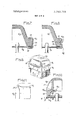
- FIG. 1 is a diagrammatic half-sectional view of an embodiment of a crimping device of the invention
- FIG. 2 is an electric diagram to feed the device of FIG. 1;
- FIGS. 3 are enlarged sectional views illustrating three embodiments of the invention in the preferred application for connecting water-boxes and collectors of a radiator for vehicle;
- FIG. 6 is a partial sectional view illustrating the application of the invention on a two fluid tubular exchanger
- FIGS. 7 and 8 are partial sectional views illustrating additional characteristics
- FIG. 9 is a partial perspective of a variant of embodi- DETAILED DESCRIPTION OF THE INVENTION
- FIG. 1 shows, in accordance with one embodiment of the invention, how the process of the invention is put into practice to ensure the fixing of water-boxes on the collectors of a radiator core.
- the core comprises tubes -1 connected to heat dissipators 2, for
- the material of the tubes 1, dissipators 2, collector's 3, 4 and water-boxes 5, 6 is not taken into consideration.
- the tubes 1 can be made of brass, aluminum or stainless steel;
- the dissipators 2 can be made of steel, copper or aluminum,
- the collectors 3 and 4 can also be made of brass, steel, treated or not treated, even made of synthetic material; and it is the same for water-boxes 5, 6.
- any usual assem bling method put into practice in technics can be applied, such as soft soldering, adhesively brazing, adhesively sticking, etc.
- the core so to speak i.e., the tubes 1, the dissipators 2 and the collectors 3, 4 are assembled; and to connect the collectors to the water-boxes, the method is as follows.
- a field shaping collar 7 is prepared preferably made of copper with beryllium and the inner wall 7a of said collar is shaped to have a form corresponding in section to the parts of collectors and water-boxes to be joined together. If the collectors and water boxes are rectangular with slightly rounded angles, then the inner wall 7a is made in a corresponding way. If the collector and- /or the water-box shows some recesses'or projections, then in the same way the wall 7a is shaped to at least approximately follow said recesses or projections.
- the field shaping collar 7 is surrounded by at least one winding 8 and as shown on FIG. 2 the ends of the winding or of each winding are connected to a pulse generator for example to the two plates of a capacitor battery 9 respectively.
- a switching component 10 is provided, for example a fast circuit-breaker which can be composed of an electronic device, said circuitbreaker being mounted in series between the capacitor battery 9 and winding 8.
- a power transformer 11 is provided, the primary winding thereof being fed by mains l2.
- the unit comprising the fields shaping collar 7 and winding 8 is mounted on a support 13 which delimits a supporting bed 14 on the top of which is put a waterbox, in the present case the box 6, with reference to FIG. 1.
- This bed is designed to keep the water-box in a correct position in relation with the shaping collar 7.
- the shaping collar is provided on wall 7a thereof, with a thin rim 15, for example made of synthetic material such as polytetrafluoroethylene or polyamide, said rim delimiting at the lower section thereof, a flange 15a used as a stop for a belt 16 centered by said rim 15,
- the belt 16 is made of electric conductive material, for example aluminum,
- This belt has also a similar shape as the collector and water-box to he slipped onto the latter.
- the belt 16 is installed into rim 15, the waterbox 6 is installed and is centered by said belt 16 and kept at a suitable level by bed 14, then the radiator core is installed in such a way that the collector 4 thereof rests on the water-box 6 while being centered by belt 16.
- the water-box 6a can be made of a relatively flexible material, for example of elastomere, and provided with a marginal flange 18 on which the belt 16 is set at the same time as on a moulding 19 of collector 4 which can in that casebe metallic.
- the collector is made of electric conductive metal, that is for example made of brass, aluminum or steel, then it is the collector 4a (FIG. 3a) which can form a belt 16a on the peripheric edge thereof, said belt 16a being then set onto the marginal flange 18 of water-box 6a.
- FIG. 4 shows that it is possible to place, between collector 4 and water-box 6b, a gasket 20 which can be made of soft material or of glue.
- the water-boxes can be made of metal without any prejudice. This is shown on FIG. 5 on which the water-box is designated by 60 while the belt 16a is directly shaped by collector 40 as shown on FIG. 3a.
- FIG. 6 illustrates an example in which the exchanger is composed ofa core of tubes 10 contained in an envelope 21, said tubes running into collector-plates 22 which are covered by end flanges 23 forming feeding boxes.
- a belt 16b, made of conductive metal is then simultaneously used as a connection between the envelope 21, the collector-plate 22 and theend flange 23. From this figure it is noticed that the field causing the warping of belt 16b has for its effect to delimit in the latter, a groove 24 when care is taken to provide the collector-plate 22 whith a diameter smaller than the one of the envelope 21 and flange 23; this is used as a mark if it becomes necessary to saw said belt 16b to disassemble the unit.
- the water-box as the one designated by reference 6d in FIG. 7, is made of material which can be warped even temporarily during the setting operation or when the material of the water-box shows some brittleness
- the lower surface 25 of the marginal flange 18 thereof delimits a housing 26 in which the collector 4b is at least partially embedded with also eventually seal 27.
- the collector 4b cooperates with the watenbox to form a very strong hollow girder, whereby preventing any temporary warping of said water-box.
- FIG. 8 shows a development of FIG. 7 according to which the collector 4b is also embedded in an housing of the water-box 18 and besides, said figure shows that it is sometimes advantageous to also provide a peripheric groove or spaced-out recesses 28 in the lateral edge of marginal flange 18 of the water-box 6e.
- a seal 29 can be placed between the collector and the water-box and, for example, said seal can be shaped as represented in FIG. 8.
- FIGS. 9 to 11 illustrate a development of the invention providing a very good rigidity of the belt (then designated by Me) when put into place and further causing said belt to exert a permanent resilient pressure on the water-box 6f and on collector 4c.
- the water-box 6f is provided at least at the four angles thereof with projecting ribs 30 the section of which is increasing from top to bottom of said water-box, these ribs presenting for example a rounded outline as shown on FIG. 10.
- the two lateral sides 16 and 16 of the belt 16e are folded above the top of marginal flange 18 of the water-box and under the collector 4c which is, preferably, embedded as in FIG. 7 and 8.
- the side 16 comes to a stop against said ribs; this increases the elongation to which the side 16, is subjected during the warping thereof.
- said side 16 is only submitted to an elongation but no one of the sections thereof is submitted to a contraction.
- the result is that the metal delimiting theside 16, stays under 5 train when folded, that makes the water-box be always applied on the top of the collector.
- Relating to side 16 it has been noticed that the same result could be obtained if the ribs 30 were extended beneath the collector and that anyway a similar result could still be obtained even without extending said ribs.
- said side 16 get folded as shown in FIGS. 10 and 11 forming at the angles of the belt a warped fold 31 which constitutes a kind of rib causing the metal of side 16;. to be also kept strained and also rendered more rigid because of the presence of said folds 31.
- each collector 3 to each water-box 5 a belt 16f is utilized and the water-box 5 is supported by a bed 14 while the belt 16f centered by the water-box and the collector eventually rests on a projected flange 14a of bed 14.
- the field shaping collar 7 is made up in the form of a single winding for example made of copper with beryllium having a shape corresponding to the one of belt 16f.
- said shaping device tends to become rounded in the linear sections thereof, or presents a largeradius of curve, whereby resulting in bringing together the sections thereof having a small radius of curve to the angles of belt 16f and consequently in increasing the setting pressure in those areas where it has been deemed necessary to dispose of a more inportant force.
- the warping of collar 7 can also be controlled and as shown in FIG. 13, support edges 36 or resilient blocks can be designed in some areas of the periphery thereof, which allows to accurately check the forces applied on the belt 16f whereby causing the setting thereof.
- support edges 36 or resilient blocks can be designed in some areas of the periphery thereof, which allows to accurately check the forces applied on the belt 16f whereby causing the setting thereof.
- FIGS. 13 and 14 it is possible as also shown in FIGS. 13 and 14 to fold at substantially 180 the edge 16f of said belt in order to pinch the turned-down edges of mutual centering 5 3 formed by the water-box 5 and the collector 3 respectively while the other edge l6f is folded at right angle on a peripheral support section of the water-box 5, ensuring a great strength to the finished assembling.
- the magneto forming pulse is of sufficient strength to cause the material to fold over an angle of substantially 180 by its own inertia.
- FIG. 14 illustrates an embodiment in which the shapin g collar comprises several superposed single windings 7 7 7,, which are respectively connected to separate generators or to separate generators or to separate outputs of a same I generator whereby the electrical pulse applied to each single winding can be adjusted.
- a more important force can be applied from single winding 7 to cause the folding of edge 16f, only from belt 7 to avoid any warping of the turned-down edges of the collector and water-box, while a strength of intermediary importance can be generated from single winding 7 to ensure the folding of edge 16f
- the invention is not restricted to the embodiments shown and described in detail for various modifications thereof can moreover be applied to it without departing the scope of the invention.
- the rim can be removed when the belt is directly formed by the collector.
- the capacitor working in relaxation can be replaced by various pulse generators as by electronic generators rendering eventually possible to successively apply several pulses to complete shaping of belt 16.
- a method for joining together two sections each having external flanges of substantially rectangular shape comprising the steps of:
- a method according to claim 1 comprising the further step on providing ribs on at least the external flange of one of said two sections.
- annular distortable ring is provided by fitting an extension on one of the two sections.
- annular distortable ring is provided by fitting an independent metal belt around said flanges between the same and said metal collar.
- a method according'to claim 1 comprising the further step of adjusting the shape of said metal coliar at suitable portions thereof.- I 4
Abstract
The process for the connection by crimping of collectors on water-boxes of heat exchangers is characterized in that parts of the collector and the water-box are surrounded by an electrically conductive metallic belt which is then submitted to at least one high electromagnetic pulse.
Description
Unite States Patent 1191 .1111 3,793,701 Chartet [4 Feb. 26, 1974 [541 PROCESS FOR THE CONNECTION BY [56] References Cited .SETTING OF COLLECTORS ON UNITED STATES PATENTS WATER'BQXES OF HEAT EXCHANGERS 746,440 12/1903 Austin 285/407 x [75] Inventor; Andre Chanel, Meudon, France 3,228,456 1/1966 Brown et al. 165/134 X 3,363,680 1/1968 Baker 165/158 Asslgneer sflclete Anonyme des Usmes 3,413,715 12/1968 Latussek et al..' 29/421 M x Chausson, Asnieres, France 3,438,115 4/1969 Humphress et a1. 29/516 X 22 F] d: D 1, 1970 1 1e ec Primary Examiner-Charlie T. Moon [21] PP 94,237 Attorney, Agent, or Firm-Imirie and Smiley [30] Foreign Application Priority Data [57] ABSTRACT Dec. 4, 1969 France 6942015 The process f h connection b i i f ll I tors on' water-boxes of heat exchangers is character- 521 US. c|..... "29/421, 29/516, 165/158, ized in that pans of the collectp, and the watepbox 285/407 are surrounded by an electrically conductive metallic [51] Int. Cl 323p 17/00 belt which i then Submitted to at least one high Cleo [58] Field of Search29/42l M, 516,157.31; 165/132,
tromagne'tic pulse.
5 Claims, 15 Drawing Figures PATENTEDFEBZB 19M 3,793,701
F161. Ficafi.
' INVENTOR ANDRE CHARTET PATENTED FEB 26 I974 SHEET 2 U? 4 'III PATENTED FEB 2 6 i974 SHEET 3 0F 4 '1 PROCESS FOR THE CONNECTION BY SETTING OF COLLECTORS ON WATER-BOXES OF HEAT EXCHANGERS BACKGROUND OF THE INVENTION An attempt has been made to connect heat exchanger water-boxes and collectors by crimping in order to avoid long and expensive welding or brazing operations. Up to now, the results thus obtained have not been satisfactory because crimping of the waterbox on the collector and vice-versa of the collector on the water-box causes undue stresses during the crimping operations on the fragile parts such as said waterboxes and especially said collectors. Besides these stresses frequently are applied in an irregular manner, often causing warping detrimental to the life of the manufactured device.
Another disadvantage is caused by the fact that the known crimping apparatuses do not allow to correctly perform such a work on angles existing on collectors and water-boxes whereby often resulting in a poor tightness.
SUMMARY OF THE INVENTION According to the invention, sections of the collector and the water-box to be connected together are surrounded by a belt of electric conductive metal, and then said belt is submitted for a very short period about a few milliseconds to the action of at least one pulse generated by a high electromagnetic field, operating substantially perpendicularly to the different sections of said belt, whereby obtaining the crimping of this belt on said collector and water-box.
FIG. 1 is a diagrammatic half-sectional view of an embodiment of a crimping device of the invention;
FIG. 2 is an electric diagram to feed the device of FIG. 1;
FIGS. 3 are enlarged sectional views illustrating three embodiments of the invention in the preferred application for connecting water-boxes and collectors of a radiator for vehicle;
FIG. 6 is a partial sectional view illustrating the application of the invention on a two fluid tubular exchanger;
FIGS. 7 and 8 are partial sectional views illustrating additional characteristics;
FIG. 9 is a partial perspective of a variant of embodi- DETAILED DESCRIPTION OF THE INVENTION FIG. 1 shows, in accordance with one embodiment of the invention, how the process of the invention is put into practice to ensure the fixing of water-boxes on the collectors of a radiator core. On this figure the core comprises tubes -1 connected to heat dissipators 2, for
example fins slipped on the tubes, or corrugated intercalary strips placed between the tubes. The ends of this core are provided with collectors 3 and 4 in communi cation with the tubes 1. Water Boxes 5 and 6 are tightly secured to collectors 3 and 4 respectively.
According to the invention, the material of the tubes 1, dissipators 2, collector's 3, 4 and water-boxes 5, 6 is not taken into consideration. For example the tubes 1 can be made of brass, aluminum or stainless steel; the dissipators 2 can be made of steel, copper or aluminum, the collectors 3 and 4 can also be made of brass, steel, treated or not treated, even made of synthetic material; and it is the same for water-boxes 5, 6. The way the tubes are connected to the collectors and the tubes to the dissipators is not taken into consideration in the embodiment of the invention actually, any usual assem bling method put into practice in technics can be applied, such as soft soldering, adhesively brazing, adhesively sticking, etc.
In the process of the invention, the core so to speak, i.e., the tubes 1, the dissipators 2 and the collectors 3, 4 are assembled; and to connect the collectors to the water-boxes, the method is as follows.
A field shaping collar 7 is prepared preferably made of copper with beryllium and the inner wall 7a of said collar is shaped to have a form corresponding in section to the parts of collectors and water-boxes to be joined together. If the collectors and water boxes are rectangular with slightly rounded angles, then the inner wall 7a is made in a corresponding way. If the collector and- /or the water-box shows some recesses'or projections, then in the same way the wall 7a is shaped to at least approximately follow said recesses or projections.
The field shaping collar 7 is surrounded by at least one winding 8 and as shown on FIG. 2 the ends of the winding or of each winding are connected to a pulse generator for example to the two plates of a capacitor battery 9 respectively. Further, a switching component 10 is provided, for example a fast circuit-breaker which can be composed of an electronic device, said circuitbreaker being mounted in series between the capacitor battery 9 and winding 8. To charge the capacitors 9, a power transformer 11 is provided, the primary winding thereof being fed by mains l2.
The unit comprising the fields shaping collar 7 and winding 8 is mounted on a support 13 which delimits a supporting bed 14 on the top of which is put a waterbox, in the present case the box 6, with reference to FIG. 1. This bed is designed to keep the water-box in a correct position in relation with the shaping collar 7.
In the example shown, the shaping collar is provided on wall 7a thereof, with a thin rim 15, for example made of synthetic material such as polytetrafluoroethylene or polyamide, said rim delimiting at the lower section thereof, a flange 15a used as a stop for a belt 16 centered by said rim 15, The belt 16 is made of electric conductive material, for example aluminum,
' copper, brass or steel. This belt has also a similar shape as the collector and water-box to he slipped onto the latter.
From above it is noticed thatin the described embodiment, the belt 16 is installed into rim 15, the waterbox 6 is installed and is centered by said belt 16 and kept at a suitable level by bed 14, then the radiator core is installed in such a way that the collector 4 thereof rests on the water-box 6 while being centered by belt 16.
These operations being performed and in supposing that the capacitor battery 9 has already been charged, only the circuit-breaker 10 has to be turned-off, which causes the discharge of the capacitors into the winding 8 thus generating in collar 7 and belt 16 the induction of eddy currents and a radial field which causes the sudden warping of the belt 16 in the areas not resting on the collector 4 and the water-box 6, thus said belt is set on the collector and the water-box, as shown in 16a, at the upper section of FIG. 1.
In order that the above described crimping operation will ensure the tightness between the collector and the water-box, many possibilities can be contemplated. For example, as shown in FIG. 3, the water-box 6a can be made of a relatively flexible material, for example of elastomere, and provided with a marginal flange 18 on which the belt 16 is set at the same time as on a moulding 19 of collector 4 which can in that casebe metallic. If the collector is made of electric conductive metal, that is for example made of brass, aluminum or steel, then it is the collector 4a (FIG. 3a) which can form a belt 16a on the peripheric edge thereof, said belt 16a being then set onto the marginal flange 18 of water-box 6a. The warping of belt 16 by an electromagnetic effect as described above occurring in a very short period of time of about 50 milliseconds, it has been noticed that the metal of the belt, during the warping thereof, was acting like a fluid and that it could be extended in some sections and contracted in some other. Consequently, the marginal flange 18 of the water-box, as shown in FIG. 4 fora collector 6b, can be provided with projections which are wrapped by the belt 16 as shown in 16,.
Also the FIG. 4 shows that it is possible to place, between collector 4 and water-box 6b, a gasket 20 which can be made of soft material or of glue.
As already mentioned, the water-boxes can be made of metal without any prejudice. This is shown on FIG. 5 on which the water-box is designated by 60 while the belt 16a is directly shaped by collector 40 as shown on FIG. 3a.
The invention can be embodied in the same way for other types of exchangers and FIG. 6 illustrates an example in which the exchanger is composed ofa core of tubes 10 contained in an envelope 21, said tubes running into collector-plates 22 which are covered by end flanges 23 forming feeding boxes. A belt 16b, made of conductive metal is then simultaneously used as a connection between the envelope 21, the collector-plate 22 and theend flange 23. From this figure it is noticed that the field causing the warping of belt 16b has for its effect to delimit in the latter, a groove 24 when care is taken to provide the collector-plate 22 whith a diameter smaller than the one of the envelope 21 and flange 23; this is used as a mark if it becomes necessary to saw said belt 16b to disassemble the unit.
Particularly when the water-box, as the one designated by reference 6d in FIG. 7, is made of material which can be warped even temporarily during the setting operation or when the material of the water-box shows some brittleness, it is then advantageous that the lower surface 25 of the marginal flange 18 thereof delimits a housing 26 in which the collector 4b is at least partially embedded with also eventually seal 27. Thus when the belt 16c is warped whereby causing the setting of the unit, the collector 4b cooperates with the watenbox to form a very strong hollow girder, whereby preventing any temporary warping of said water-box.
It has been noticed that the belt is thus better applied on all the sections of the water-box and collector that it has to fit on, and the result is that the seal 27 is strongly compressed. This ensures an assembling of a very good holding and a perfect tightness.
FIG. 8 shows a development of FIG. 7 according to which the collector 4b is also embedded in an housing of the water-box 18 and besides, said figure shows that it is sometimes advantageous to also provide a peripheric groove or spaced-out recesses 28 in the lateral edge of marginal flange 18 of the water-box 6e.
As mentioned above, a seal 29 can be placed between the collector and the water-box and, for example, said seal can be shaped as represented in FIG. 8.
At the moment of the warping of belt 16d the latter penetrates into the groove or into housings 28 while getting folded beneath the water-box and collector. This embodiment ensures an extremely intimate joint of the two parts to be connected together, while making rigid the periphery of the belt due to the fact of the warping 16d, that said belt has to sustain in order to fit at least partially on the groove or housings 28.
FIGS. 9 to 11 illustrate a development of the invention providing a very good rigidity of the belt (then designated by Me) when put into place and further causing said belt to exert a permanent resilient pressure on the water-box 6f and on collector 4c. For that purpose the water-box 6f is provided at least at the four angles thereof with projecting ribs 30 the section of which is increasing from top to bottom of said water-box, these ribs presenting for example a rounded outline as shown on FIG. 10. At the moment of the warping sustained by belt 16:: through action of the electromagnetic field developed from the discharge current, the two lateral sides 16 and 16 of the belt 16e are folded above the top of marginal flange 18 of the water-box and under the collector 4c which is, preferably, embedded as in FIG. 7 and 8.
Because of the presence of ribs 30, the side 16 comes to a stop against said ribs; this increases the elongation to which the side 16, is subjected during the warping thereof.
In that case it is noticed that said side 16, is only submitted to an elongation but no one of the sections thereof is submitted to a contraction. The result is that the metal delimiting theside 16, stays under 5 train when folded, that makes the water-box be always applied on the top of the collector. Relating to side 16 it has been noticed that the same result could be obtained if the ribs 30 were extended beneath the collector and that anyway a similar result could still be obtained even without extending said ribs. In fact, in that case, and by suitably setting the power of the shaping pulses, said side 16 get folded as shown in FIGS. 10 and 11 forming at the angles of the belt a warped fold 31 which constitutes a kind of rib causing the metal of side 16;. to be also kept strained and also rendered more rigid because of the presence of said folds 31.
According to FIGS. 11 to 13, to assemble each collector 3 to each water-box 5, a belt 16f is utilized and the water-box 5 is supported by a bed 14 while the belt 16f centered by the water-box and the collector eventually rests on a projected flange 14a of bed 14.
The field shaping collar 7 is made up in the form of a single winding for example made of copper with beryllium having a shape corresponding to the one of belt 16f.
except for the core 34 to which it is connected, it is freely mounted on the' top of flange 14a of bed 14 to.
be able to become out of shape or distorted at least in some of the sections thereof when it is run through by the discharge current of the capacitors 9.
Accordingly during the warping that it sustains under the influence of the mutual electromagnetic repulsion generated between itself and the belt 16f at the moment of the discharge of capacitors 9, said shaping device tends to become rounded in the linear sections thereof, or presents a largeradius of curve, whereby resulting in bringing together the sections thereof having a small radius of curve to the angles of belt 16f and consequently in increasing the setting pressure in those areas where it has been deemed necessary to dispose of a more inportant force.
The warping of collar 7 can also be controlled and as shown in FIG. 13, support edges 36 or resilient blocks can be designed in some areas of the periphery thereof, which allows to accurately check the forces applied on the belt 16f whereby causing the setting thereof. Thus it is possible as also shown in FIGS. 13 and 14 to fold at substantially 180 the edge 16f of said belt in order to pinch the turned-down edges of mutual centering 5 3 formed by the water-box 5 and the collector 3 respectively while the other edge l6f is folded at right angle on a peripheral support section of the water-box 5, ensuring a great strength to the finished assembling. The magneto forming pulse is of sufficient strength to cause the material to fold over an angle of substantially 180 by its own inertia.
FIG. 14 illustrates an embodiment in which the shapin g collar comprises several superposed single windings 7 7 7,, which are respectively connected to separate generators or to separate generators or to separate outputs of a same I generator whereby the electrical pulse applied to each single winding can be adjusted. Through that way it is moreover possible to vary the forces applied to the different zones of the belt 16f, for
example a more important force can be applied from single winding 7 to cause the folding of edge 16f, only from belt 7 to avoid any warping of the turned-down edges of the collector and water-box, while a strength of intermediary importance can be generated from single winding 7 to ensure the folding of edge 16f The invention is not restricted to the embodiments shown and described in detail for various modifications thereof can moreover be applied to it without departing the scope of the invention. Particularly, the rim can be removed when the belt is directly formed by the collector. Also the capacitor working in relaxation can be replaced by various pulse generators as by electronic generators rendering eventually possible to successively apply several pulses to complete shaping of belt 16.
I claim:
l. A method for joining together two sections each having external flanges of substantially rectangular shape, comprising the steps of:
positioning the two sections with their external flanges in engagement; disposing around said flanges an annular plastically deformable magnetically responsive metal ring approximating the cross-sectional contour of the said flanges;
disposing at least one substantially rectangular resilient electrically conductive metal collar in surrounding relation to said annular distortable ring; and
connecting said at least one metal collar to a pulse power generator whereby said collar is energized thus magneto forming said ring while resiliently deforming a suitable portion of said collar whereby the ring will be uniformly deformed onto said flanges.
2. A method according to claim 1 comprising the further step on providing ribs on at least the external flange of one of said two sections.
3. A method according to claim 1 wherein said annular distortable ring is provided by fitting an extension on one of the two sections.
4. A method according to claim 1 wherein said annular distortable ring is provided by fitting an independent metal belt around said flanges between the same and said metal collar.
5. A method according'to claim 1 comprising the further step of adjusting the shape of said metal coliar at suitable portions thereof.- I 4
Claims (5)
1. A method for joining together two sections each having external flanges of substantially rectangular shape, comprising the steps of: positioning the two sections with their external flanges in engagement; disposing around said flanges an annular plastically deformable magnetically responsive metal ring approximating the crosssectional contour of the said flanges; disposing at least one substantially rectangular resilient electrically conductive metal collar in surrounding relation to said annular distortable ring; and connecting said at least one metal collar to a pulse power generator whereby said collar is energized thus magneto forming said ring while resiliently deforming a suitable portion of said collar whereby the ring will be uniformly deformed onto said flanges.
2. A method according to claim 1 comprising the further step on providing ribs on at least the external flange of one of said two sections.
3. A method according to claim 1 wherein said annular distortable ring is provided by fitting an extension on one of the two sections.
4. A method according to claim 1 wherein said annular distortable ring is provided by fitting an independent metal belt around said flanges between the same and said metal collar.
5. A method according to claim 1 comprising the further step of adjusting the shape of said metal collar at suitable portions thereof.
Applications Claiming Priority (1)
| Application Number | Priority Date | Filing Date | Title |
|---|---|---|---|
| FR6942015A FR2070448A5 (en) | 1969-12-04 | 1969-12-04 |
Publications (1)
| Publication Number | Publication Date |
|---|---|
| US3793701A true US3793701A (en) | 1974-02-26 |
Family
ID=9044123
Family Applications (1)
| Application Number | Title | Priority Date | Filing Date |
|---|---|---|---|
| US00094237A Expired - Lifetime US3793701A (en) | 1969-12-04 | 1970-12-01 | Process for the connection by setting of collectors on water-boxes of heat exchangers |
Country Status (6)
| Country | Link |
|---|---|
| US (1) | US3793701A (en) |
| BE (1) | BE759681A (en) |
| DE (1) | DE2059855A1 (en) |
| ES (2) | ES386074A1 (en) |
| FR (1) | FR2070448A5 (en) |
| GB (1) | GB1339569A (en) |
Cited By (10)
| Publication number | Priority date | Publication date | Assignee | Title |
|---|---|---|---|---|
| US4039377A (en) * | 1974-03-20 | 1977-08-02 | Commissariat A L'energie Atomique | Nuclear boiler |
| US4877264A (en) * | 1988-12-27 | 1989-10-31 | Talley Automotive Products, Inc. | Aspirating/venting air bag module assembly |
| US4913461A (en) * | 1988-12-27 | 1990-04-03 | Talley Automotive Products, Inc. | Airbag module and method of making same |
| JPH02169345A (en) * | 1988-09-16 | 1990-06-29 | Talley Automot Prod Inc | Light weight and non-weld expander |
| USRE33938E (en) * | 1988-12-27 | 1992-05-26 | Talley Automotive Products, Inc. | Aspirating/venting air bag module assembly |
| US6223812B1 (en) * | 1998-12-07 | 2001-05-01 | Serck Heat Transfer Limited | Heat exchanger core connection |
| US20080007066A1 (en) * | 2005-05-17 | 2008-01-10 | Wykoff Curtiss F | Pneumatic conveying line component |
| US20160334174A1 (en) * | 2015-05-15 | 2016-11-17 | Hanon Systems | Header for heat exchanger |
| US9726371B2 (en) | 2013-05-08 | 2017-08-08 | Whirlpool Corporation | Glass and metal burner cap and method of making the same |
| EP2696062B1 (en) * | 2012-08-09 | 2018-05-16 | MAHLE Behr GmbH & Co. KG | Heat exchanger |
Families Citing this family (7)
| Publication number | Priority date | Publication date | Assignee | Title |
|---|---|---|---|---|
| LU73231A1 (en) * | 1975-08-21 | 1977-04-15 | ||
| DE2852408B2 (en) * | 1978-12-04 | 1981-10-01 | Süddeutsche Kühlerfabrik Julius Fr. Behr GmbH & Co KG, 7000 Stuttgart | Clamp connection |
| DE2852415B2 (en) * | 1978-12-04 | 1981-04-30 | Süddeutsche Kühlerfabrik Julius Fr. Behr GmbH & Co KG, 7000 Stuttgart | Clamp connection |
| GB2074054B (en) * | 1980-04-17 | 1983-05-18 | British Leyland Cars Ltd | Manufacturing heat exchangers |
| JPS57132989U (en) * | 1981-02-04 | 1982-08-19 | ||
| CA1247591A (en) * | 1984-06-28 | 1988-12-28 | Kevin E. Stay | Tank header plate connection |
| FR2589970A1 (en) * | 1985-11-08 | 1987-05-15 | Bonafous Jean | Assembly of a bellows by magnetic forming |
Citations (5)
| Publication number | Priority date | Publication date | Assignee | Title |
|---|---|---|---|---|
| US746440A (en) * | 1902-03-27 | 1903-12-08 | Burnham Williams & Co | Joint for containers. |
| US3228456A (en) * | 1965-03-01 | 1966-01-11 | Du Pont | Method and apparatus employing hollow polyfluorinated plastic filaments for heat exchange |
| US3363680A (en) * | 1966-07-21 | 1968-01-16 | Du Pont | Plastic tube heat exchanger with novel header construction |
| US3413715A (en) * | 1965-07-13 | 1968-12-03 | Siemens Ag | Apparatus and method for producing the stator of a dc miniature motor |
| US3438115A (en) * | 1967-11-30 | 1969-04-15 | Union Carbide Corp | Method of making vacuum containers |
-
0
- BE BE759681D patent/BE759681A/en unknown
-
1969
- 1969-12-04 FR FR6942015A patent/FR2070448A5/fr not_active Expired
-
1970
- 1970-12-01 GB GB5713170A patent/GB1339569A/en not_active Expired
- 1970-12-01 ES ES386074A patent/ES386074A1/en not_active Expired
- 1970-12-01 US US00094237A patent/US3793701A/en not_active Expired - Lifetime
- 1970-12-04 DE DE19702059855 patent/DE2059855A1/en active Pending
-
1971
- 1971-01-13 ES ES387233A patent/ES387233A1/en not_active Expired
Patent Citations (5)
| Publication number | Priority date | Publication date | Assignee | Title |
|---|---|---|---|---|
| US746440A (en) * | 1902-03-27 | 1903-12-08 | Burnham Williams & Co | Joint for containers. |
| US3228456A (en) * | 1965-03-01 | 1966-01-11 | Du Pont | Method and apparatus employing hollow polyfluorinated plastic filaments for heat exchange |
| US3413715A (en) * | 1965-07-13 | 1968-12-03 | Siemens Ag | Apparatus and method for producing the stator of a dc miniature motor |
| US3363680A (en) * | 1966-07-21 | 1968-01-16 | Du Pont | Plastic tube heat exchanger with novel header construction |
| US3438115A (en) * | 1967-11-30 | 1969-04-15 | Union Carbide Corp | Method of making vacuum containers |
Cited By (13)
| Publication number | Priority date | Publication date | Assignee | Title |
|---|---|---|---|---|
| US4039377A (en) * | 1974-03-20 | 1977-08-02 | Commissariat A L'energie Atomique | Nuclear boiler |
| JPH02169345A (en) * | 1988-09-16 | 1990-06-29 | Talley Automot Prod Inc | Light weight and non-weld expander |
| JP2618052B2 (en) | 1988-09-16 | 1997-06-11 | タリ オートモウティヴ プロダクツ インコーポレーテッド | Lightweight non-weld expansion device |
| US4877264A (en) * | 1988-12-27 | 1989-10-31 | Talley Automotive Products, Inc. | Aspirating/venting air bag module assembly |
| US4913461A (en) * | 1988-12-27 | 1990-04-03 | Talley Automotive Products, Inc. | Airbag module and method of making same |
| USRE33938E (en) * | 1988-12-27 | 1992-05-26 | Talley Automotive Products, Inc. | Aspirating/venting air bag module assembly |
| US6223812B1 (en) * | 1998-12-07 | 2001-05-01 | Serck Heat Transfer Limited | Heat exchanger core connection |
| US20080007066A1 (en) * | 2005-05-17 | 2008-01-10 | Wykoff Curtiss F | Pneumatic conveying line component |
| US7547046B2 (en) * | 2005-05-17 | 2009-06-16 | The Young Industries, Inc. | Pneumatic conveying line component |
| EP2696062B1 (en) * | 2012-08-09 | 2018-05-16 | MAHLE Behr GmbH & Co. KG | Heat exchanger |
| US9726371B2 (en) | 2013-05-08 | 2017-08-08 | Whirlpool Corporation | Glass and metal burner cap and method of making the same |
| US20160334174A1 (en) * | 2015-05-15 | 2016-11-17 | Hanon Systems | Header for heat exchanger |
| US10852074B2 (en) * | 2015-05-15 | 2020-12-01 | Hanon Systems | Header for heat exchanger |
Also Published As
| Publication number | Publication date |
|---|---|
| GB1339569A (en) | 1973-12-05 |
| BE759681A (en) | 1971-04-30 |
| ES387233A1 (en) | 1973-05-01 |
| ES386074A1 (en) | 1973-03-16 |
| FR2070448A5 (en) | 1971-09-10 |
| DE2059855A1 (en) | 1971-06-09 |
Similar Documents
| Publication | Publication Date | Title |
|---|---|---|
| US3793701A (en) | Process for the connection by setting of collectors on water-boxes of heat exchangers | |
| CN101345441A (en) | Electric miniature drive and inference element and production method for same | |
| US4324290A (en) | Heat exchanger comprising a core of tubes engaged inside end plates mechanically connected with header boxes | |
| US3805569A (en) | Apparatus for the connection by setting of collectors on water-boxes of heat exchangers | |
| US3438115A (en) | Method of making vacuum containers | |
| GB2109712B (en) | Manufacturing the peripheral wall of a tank for an oil-immersed electric apparatus | |
| CN106572606B (en) | A kind of discrete device and printed circuit board integrative installation technology method | |
| CA2688236C (en) | Multiple tube processing coil | |
| JPH05290902A (en) | Conductor contact maker | |
| US20060156776A1 (en) | Method and apparatus for performing a magnetic pulse forming process | |
| US1812748A (en) | Dynamo electric machine | |
| EP1059651A2 (en) | Apparatus and associated method for supporting a vacuum interrupter sub-assembly during manufacture | |
| US3277559A (en) | Method of cold pressure welding | |
| CN112562991B (en) | Heat radiator for dry-type transformer coil | |
| CN205194479U (en) | Power transformer and have this power transformer's gas shielded arc welding equipment | |
| US3947955A (en) | Method of making an inductive stabilizing ballast for a gas and/or vapour discharge lamp | |
| JP3551732B2 (en) | Stator for rotating electric machine | |
| FR2427002A1 (en) | ELECTRICAL ENERGY CONVERTER FOR ROLLING STOCK | |
| US8360793B2 (en) | Connector fitting structure and electric apparatus using the same | |
| JP7088122B2 (en) | Power converter | |
| CN211304360U (en) | Electromagnetic flanging forming device for special-shaped holes of thin plate | |
| KR0139840Y1 (en) | Transformer for neon tube | |
| GB906942A (en) | Casing ring for electric machines and method of making same | |
| JPS5930591Y2 (en) | Stator structure of rotating electric machine | |
| SU1275559A1 (en) | Method of assembling concentric cylindrical winding of power transformer |