US3845764A - Device for applying material to the area of the eye - Google Patents
Device for applying material to the area of the eye Download PDFInfo
- Publication number
- US3845764A US3845764A US00385615A US38561573A US3845764A US 3845764 A US3845764 A US 3845764A US 00385615 A US00385615 A US 00385615A US 38561573 A US38561573 A US 38561573A US 3845764 A US3845764 A US 3845764A
- Authority
- US
- United States
- Prior art keywords
- mirror
- eye
- container
- gripping means
- applying
- Prior art date
- Legal status (The legal status is an assumption and is not a legal conclusion. Google has not performed a legal analysis and makes no representation as to the accuracy of the status listed.)
- Expired - Lifetime
Links
Images
Classifications
-
- A—HUMAN NECESSITIES
- A61—MEDICAL OR VETERINARY SCIENCE; HYGIENE
- A61F—FILTERS IMPLANTABLE INTO BLOOD VESSELS; PROSTHESES; DEVICES PROVIDING PATENCY TO, OR PREVENTING COLLAPSING OF, TUBULAR STRUCTURES OF THE BODY, e.g. STENTS; ORTHOPAEDIC, NURSING OR CONTRACEPTIVE DEVICES; FOMENTATION; TREATMENT OR PROTECTION OF EYES OR EARS; BANDAGES, DRESSINGS OR ABSORBENT PADS; FIRST-AID KITS
- A61F9/00—Methods or devices for treatment of the eyes; Devices for putting-in contact lenses; Devices to correct squinting; Apparatus to guide the blind; Protective devices for the eyes, carried on the body or in the hand
- A61F9/0008—Introducing ophthalmic products into the ocular cavity or retaining products therein
-
- A—HUMAN NECESSITIES
- A45—HAND OR TRAVELLING ARTICLES
- A45D—HAIRDRESSING OR SHAVING EQUIPMENT; EQUIPMENT FOR COSMETICS OR COSMETIC TREATMENTS, e.g. FOR MANICURING OR PEDICURING
- A45D44/00—Other cosmetic or toiletry articles, e.g. for hairdressers' rooms
-
- A—HUMAN NECESSITIES
- A61—MEDICAL OR VETERINARY SCIENCE; HYGIENE
- A61F—FILTERS IMPLANTABLE INTO BLOOD VESSELS; PROSTHESES; DEVICES PROVIDING PATENCY TO, OR PREVENTING COLLAPSING OF, TUBULAR STRUCTURES OF THE BODY, e.g. STENTS; ORTHOPAEDIC, NURSING OR CONTRACEPTIVE DEVICES; FOMENTATION; TREATMENT OR PROTECTION OF EYES OR EARS; BANDAGES, DRESSINGS OR ABSORBENT PADS; FIRST-AID KITS
- A61F9/00—Methods or devices for treatment of the eyes; Devices for putting-in contact lenses; Devices to correct squinting; Apparatus to guide the blind; Protective devices for the eyes, carried on the body or in the hand
- A61F9/0061—Devices for putting-in contact lenses
Definitions
- ABSTRACT A device to be used for applying materials to the area of the eye which comprises an applying means for applying materials to the area and a mirror so that the user can see his eye reflected therein during the applying process.
- This invention relates to an applying device and more particularly to a device for applying the materials to the area of the eye.
- the present invention relates to a device to be used for applying materials to the area of the eye which comprises applying means, and a mirror supported by the device in spaced relation from the applying means and in generally facing relation thereto.
- the user When applying materials to the eye or the area surrounding the eye, the user merely focuses on his own eye as reflected in the mirror. This obviates all desire for blinking or closing the eye so that the material can be applied as desired.
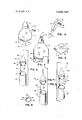
- FIG. I is a perspective view of an eye dropper constructed in accordance with one form of the invention.
- FIG. 2 is a side elevation view of the eye dropper illustrated in FIG. 1 with portions thereof broken away to show its construction.
- FIG. 3 is a plan view of the eye dropper illustrated in FIG. 1.
- FIG. 4 is a schematic drawing of the eye dropper illustrated in FIG. I as used.
- FIG. 5 is a perspective view-of another embodiment of the invention.
- FIG. 6 is a perspective view of a further embodiment of the invention.
- FIG. 7 is a perspective view of still another embodiment of the invention.
- FIG. 8 is a plan view ofa portion of the device shown in FIG. 7.
- the applying device may be an eye dropper or other container which comprises a resilient peripheral wall 12.
- the outer surface of the wall 12 functions as a gripping surface.
- the container is closed at its lower end and has an outlet 14 at its upper end which is capable of dispensing material in drop form.
- the outlet 14 may be closed by a suitable cap 16 when the container is not being used.
- a ledge 18 or other suitable supporting surface may be formed in the side wall of the container.
- the ledge supports a mirror 20 which has its reflective surface turned in generally facing relation to the outlet 14.
- the ledge is in spaced relation from the outlet 14 and the mirror is concave so that focusing is achieved when the eye is close to the outlet 14. This assures that drops which are dispensed from the container will .fall directly into the eye.
- a device for applying a cosmetic to the area of the eye 24 comprises a handle 26 having a surface 28 which defines a support for a mirror 30.
- An elongated member 32 is supported at one end by surface 28 adjacent the periphery of mirror 30. At its free end, it supports a suitable cosmetic applying device 34.
- the applying device is a brush.
- a step 38 is formed in the periphery of the handle 26 so that the handle may be received in a hollow cosmetic container 40.
- the mirror 30 may be planar. However, it is preferred that it be concave and have a focus such that the eye will be in focus when the brush is touching the eye.
- the applying device 44 is virtually identical to the embodiment illustrated in FIG. 5.
- this embodiment is particularly usable for applying and removing contact lenses since it has a suction cup 46 at the end of elongated member 48.
- the mirror 50 is preferably concave and the container 52 has suitable: means therein for supporting the contact lenses when not in use.
- the applying device 56 shown in FIG. 7 is similar to that shown in FIG. 6. However, in this embodiment, the suction cup 58 is surrounded by an annulus 60 having a plurality of apertures 62 therein (FIG. 8). In this embodiment, a reservoir is formed on the interior of handle 64 and its walls are made of a resilient material. The elongated member 66 which is hollow forms a conduit connecting the reservoir within handle 64 to the annulus 60. Container 68 may be used to store contact lenses in a manner similar to that described in connection with the embodiment of FIG. 6,. Thus, with the device shown in FIG. 7, medication can be dropped into the eye after the contact lens has been removed. Then, the lens can be replaced thereafter.
- the mirror 70 may be planar. However, it .is preferred that it be concave with its focus located a sufficient distance away from its surface to permit proper positioning of the suction cup 58 and annulus 56.
- a device to be used for applying materials to the area of the eye comprising an elongated member, gripping means including a container, a mirror, said mirror being supported by said gripping means in spaced relation from said member, said elongated member being supported at one end by said gripping means and hav ing an applying tool at its other end, said applying tool being a suction cup surrounded by a hollow annulus, said annulus having a plurality of apertures therein to permit a liquid to be dispensed therefrom, and conduit means providing communication between said container and said annulus.
- said gripping means comprises the walls of said container, a ledge formed at at least one wall of said container for supporting said mirror, and said elongated member being offset with respect to the longitudinal axis of said container and projecting from said wall of said container alongside said mirror.
- a device to be used for applying materials to the area surrounding the eye comprising gripping means, said gripping means defining a surface, a mirror supported on said surface. an elongated member supported by said gripping means at the periphery of said mirror, an applying tool supported at the free end of said elongated member, said gripping means being a resilient hollow member, said applying tool being a suction cup surrounded by a hollow annulus, said annulus having a plurality of apertures therethrough, said elongated member being a conduit between said resilient hollow member and said annulus to permit a liquid to be dispensed therefrom.
- a device in accordance with claim 4 wherein said elongated member is connected to said resilient hollow member adjacent the periphery thereof and alongside said mirror, said mirror being concave.
Abstract
A device to be used for applying materials to the area of the eye which comprises an applying means for applying materials to the area and a mirror so that the user can see his eye reflected therein during the applying process.
Description
United States Patent 11 1 Windsor 1 1 DEVICE FOR APPLYING MATERIAL TO THE AREA OF THE EYE 1761 Inventor: Robert I(. Windsor, P0. 417
[221 Filed: Aug. 3, 1973 121] Appl. No.1 385,615
Related U.S. Application Data [62] Division ofScr. No. 262.384. June 13, 1972. Pat.'N0.
[52] U.S. Cl 128/233, 128/260, 401/118 [51] Int. Cl A61m 1/00 [58] Field of Search 128/233, 173, 249, 260;
156] References Cited UNITED STATES PATENTS 2.379.629 7/1945 Eweson .1 294/64 Spruce St., Philadelphia. Pa. 19106 Primary Examiner-Richard A. Gaudet Assistant Examiner-J. Yasko Attorney. Agent. or FirmScide1, Gonda & Goldhammcr [5 7] ABSTRACT A device to be used for applying materials to the area of the eye which comprises an applying means for applying materials to the area and a mirror so that the user can see his eye reflected therein during the applying process.
5 Claims, 8 Drawing Figures DEVICE FOR APPLYING MATERIAL TO THE AREA OF Til-IE EYE This patent application is a divisional patent application of patent application Ser. No. 262,384 filed June 13, 1972 now US. Pat. 3,779,245.
This invention relates to an applying device and more particularly to a device for applying the materials to the area of the eye.
Many people have a substantial amount of difficulty in applying materials to the eye or to the region of the eye. These persons find it very difficult to apply drops to their eyes or to remove or place contact lenses therein. This is because the eye has a natural tendency to blink or close as a foreign object approaches. A similar problem is encountered in the application of cosmetics such as eye liner, mascara and the like.
It is believed that the eye finds the approach of objects to be offensive because of its inability to focus on them.
The disadvantages outlined above have been overcome by the present invention. Thus, the present invention relates to a device to be used for applying materials to the area of the eye which comprises applying means, and a mirror supported by the device in spaced relation from the applying means and in generally facing relation thereto. When applying materials to the eye or the area surrounding the eye, the user merely focuses on his own eye as reflected in the mirror. This obviates all desire for blinking or closing the eye so that the material can be applied as desired.
The invention can best be described by referring to the drawing and following specification where a num ber of embodiments thereof are illustrated. However, it should be understood that these embodiments are merely exemplary and the invention should not be limited thereby.
In the drawings, FIG. I is a perspective view of an eye dropper constructed in accordance with one form of the invention.
FIG. 2 is a side elevation view of the eye dropper illustrated in FIG. 1 with portions thereof broken away to show its construction.
FIG. 3 is a plan view of the eye dropper illustrated in FIG. 1.
FIG. 4 is a schematic drawing of the eye dropper illustrated in FIG. I as used.
FIG. 5 is a perspective view-of another embodiment of the invention.
FIG. 6 is a perspective view ofa further embodiment of the invention.
FIG. 7 is a perspective view of still another embodiment of the invention.
FIG. 8 is a plan view ofa portion of the device shown in FIG. 7.
Now referring to the drawing for a detailed description of the invention, an applying device 10 is illustrated in FIG. I. In this embodiment of the invention, the applying device may be an eye dropper or other container which comprises a resilient peripheral wall 12. The outer surface of the wall 12 functions as a gripping surface. The container is closed at its lower end and has an outlet 14 at its upper end which is capable of dispensing material in drop form. The outlet 14 may be closed by a suitable cap 16 when the container is not being used.
As best seen in FIGS. 1 and 2, a ledge 18 or other suitable supporting surface may be formed in the side wall of the container. The ledge supports a mirror 20 which has its reflective surface turned in generally facing relation to the outlet 14. Preferably, the ledge is in spaced relation from the outlet 14 and the mirror is concave so that focusing is achieved when the eye is close to the outlet 14. This assures that drops which are dispensed from the container will .fall directly into the eye.
In FIG. 5, a device for applying a cosmetic to the area of the eye 24 is illustrated. It comprises a handle 26 having a surface 28 which defines a support for a mirror 30. An elongated member 32 is supported at one end by surface 28 adjacent the periphery of mirror 30. At its free end, it supports a suitable cosmetic applying device 34. In the embodiment shown, the applying device is a brush. A step 38 is formed in the periphery of the handle 26 so that the handle may be received in a hollow cosmetic container 40. Thus, when assembled, the elongated member 32 and the cosmetic applying device 34 are in the container and protectedfrom damage.
The mirror 30 may be planar. However, it is preferred that it be concave and have a focus such that the eye will be in focus when the brush is touching the eye.
In the embodiment of the invention illustrated in FIG. 6, the applying device 44 is virtually identical to the embodiment illustrated in FIG. 5. However, this embodiment is particularly usable for applying and removing contact lenses since it has a suction cup 46 at the end of elongated member 48.
In this regard, the mirror 50 is preferably concave and the container 52 has suitable: means therein for supporting the contact lenses when not in use.
As is well known, sufficient adherence of a contact lens to cup 46 will be achieved by merely moistening the cup.
The applying device 56 shown in FIG. 7 is similar to that shown in FIG. 6. However, in this embodiment, the suction cup 58 is surrounded by an annulus 60 having a plurality of apertures 62 therein (FIG. 8). In this embodiment, a reservoir is formed on the interior of handle 64 and its walls are made of a resilient material. The elongated member 66 which is hollow forms a conduit connecting the reservoir within handle 64 to the annulus 60. Container 68 may be used to store contact lenses in a manner similar to that described in connection with the embodiment of FIG. 6,. Thus, with the device shown in FIG. 7, medication can be dropped into the eye after the contact lens has been removed. Then, the lens can be replaced thereafter. It can be done in a simple operation with the mirror 70 obviating the tendency of the eye to blink. As explained above, the mirror 70 may be planar. However, it .is preferred that it be concave with its focus located a sufficient distance away from its surface to permit proper positioning of the suction cup 58 and annulus 56.
While the invention has been described with reference to a number of embodiments thereof, it is apparent that many other forms and embodiments be obvious to those skilled in the art in view of the foregoing description. Thus, the scope of the invention should not be limited by that description but rather, only by the scope of the claims appended hereto.
I claim:
I. A device to be used for applying materials to the area of the eye comprising an elongated member, gripping means including a container, a mirror, said mirror being supported by said gripping means in spaced relation from said member, said elongated member being supported at one end by said gripping means and hav ing an applying tool at its other end, said applying tool being a suction cup surrounded by a hollow annulus, said annulus having a plurality of apertures therein to permit a liquid to be dispensed therefrom, and conduit means providing communication between said container and said annulus.
2. A device in accordance with claim 1 wherein said mirror is generally concave.
3. A device in accordance with claim 1 wherein said gripping means comprises the walls of said container, a ledge formed at at least one wall of said container for supporting said mirror, and said elongated member being offset with respect to the longitudinal axis of said container and projecting from said wall of said container alongside said mirror.
4. A device to be used for applying materials to the area surrounding the eye comprising gripping means, said gripping means defining a surface, a mirror supported on said surface. an elongated member supported by said gripping means at the periphery of said mirror, an applying tool supported at the free end of said elongated member, said gripping means being a resilient hollow member, said applying tool being a suction cup surrounded by a hollow annulus, said annulus having a plurality of apertures therethrough, said elongated member being a conduit between said resilient hollow member and said annulus to permit a liquid to be dispensed therefrom.
5. A device in accordance with claim 4 wherein said elongated member is connected to said resilient hollow member adjacent the periphery thereof and alongside said mirror, said mirror being concave.
Claims (5)
1. A device to be used for applying materials to the area of the eye comprising an elongated member, gripping means including a container, a mirror, said mirror being supported by said gripping means in spaced relation from said member, said elongated member being supported at one end by said gripping means and having an applying tool at its other end, said applying tool being a suction cup surrounded by a hollow annulus, said annulus having a plurality of apertures therein to permit a liquid to be dispensed therefrom, and conduit means providing communication between said container and said annulus.
2. A device in accordance with claim 1 wherein said mirror is generally concAve.
3. A device in accordance with claim 1 wherein said gripping means comprises the walls of said container, a ledge formed at at least one wall of said container for supporting said mirror, and said elongated member being offset with respect to the longitudinal axis of said container and projecting from said wall of said container alongside said mirror.
4. A device to be used for applying materials to the area surrounding the eye comprising gripping means, said gripping means defining a surface, a mirror supported on said surface, an elongated member supported by said gripping means at the periphery of said mirror, an applying tool supported at the free end of said elongated member, said gripping means being a resilient hollow member, said applying tool being a suction cup surrounded by a hollow annulus, said annulus having a plurality of apertures therethrough, said elongated member being a conduit between said resilient hollow member and said annulus to permit a liquid to be dispensed therefrom.
5. A device in accordance with claim 4 wherein said elongated member is connected to said resilient hollow member adjacent the periphery thereof and alongside said mirror, said mirror being concave.
Priority Applications (1)
| Application Number | Priority Date | Filing Date | Title |
|---|---|---|---|
| US00385615A US3845764A (en) | 1972-06-13 | 1973-08-03 | Device for applying material to the area of the eye |
Applications Claiming Priority (2)
| Application Number | Priority Date | Filing Date | Title |
|---|---|---|---|
| US26238472A | 1972-06-13 | 1972-06-13 | |
| US00385615A US3845764A (en) | 1972-06-13 | 1973-08-03 | Device for applying material to the area of the eye |
Publications (1)
| Publication Number | Publication Date |
|---|---|
| US3845764A true US3845764A (en) | 1974-11-05 |
Family
ID=26949181
Family Applications (1)
| Application Number | Title | Priority Date | Filing Date |
|---|---|---|---|
| US00385615A Expired - Lifetime US3845764A (en) | 1972-06-13 | 1973-08-03 | Device for applying material to the area of the eye |
Country Status (1)
| Country | Link |
|---|---|
| US (1) | US3845764A (en) |
Cited By (14)
| Publication number | Priority date | Publication date | Assignee | Title |
|---|---|---|---|---|
| GB2279254A (en) * | 1993-05-25 | 1995-01-04 | Perstorp Pharma Ltd | Apparatus for self-administration of a medicament |
| US6223947B1 (en) | 1999-02-02 | 2001-05-01 | Byron W. Bernard | Eye dropper with illuminated tip |
| US20070052926A1 (en) * | 2005-09-07 | 2007-03-08 | Yusheng Li | Eye drop aimer system |
| US20070074889A1 (en) * | 2004-12-21 | 2007-04-05 | Thomas & Betts International, Inc. | Self-supporting electrical fixture support |
| US7883031B2 (en) | 2003-05-20 | 2011-02-08 | James F. Collins, Jr. | Ophthalmic drug delivery system |
| US8012136B2 (en) | 2003-05-20 | 2011-09-06 | Optimyst Systems, Inc. | Ophthalmic fluid delivery device and method of operation |
| US8684980B2 (en) | 2010-07-15 | 2014-04-01 | Corinthian Ophthalmic, Inc. | Drop generating device |
| US8733935B2 (en) | 2010-07-15 | 2014-05-27 | Corinthian Ophthalmic, Inc. | Method and system for performing remote treatment and monitoring |
| US9087145B2 (en) | 2010-07-15 | 2015-07-21 | Eyenovia, Inc. | Ophthalmic drug delivery |
| WO2016001453A1 (en) * | 2014-07-02 | 2016-01-07 | De Miguel Simó Pedro Víctor | Collyrium applicator |
| WO2018007689A1 (en) * | 2016-07-07 | 2018-01-11 | Heikkilä Pia | Instrument and method for keeping an eye open |
| US10154923B2 (en) | 2010-07-15 | 2018-12-18 | Eyenovia, Inc. | Drop generating device |
| US10639194B2 (en) | 2011-12-12 | 2020-05-05 | Eyenovia, Inc. | High modulus polymeric ejector mechanism, ejector device, and methods of use |
| US11938056B2 (en) | 2017-06-10 | 2024-03-26 | Eyenovia, Inc. | Methods and devices for handling a fluid and delivering the fluid to the eye |
Citations (8)
| Publication number | Priority date | Publication date | Assignee | Title |
|---|---|---|---|---|
| US2379629A (en) * | 1943-10-13 | 1945-07-03 | Eric W Eweson | Device for manipulating contact lenses |
| US2382771A (en) * | 1944-03-17 | 1945-08-14 | Louis E Bowers | Medicine dropper |
| US2410257A (en) * | 1945-12-05 | 1946-10-29 | Joseph Belzowski | Mechanism for removing foreign particles from the eye |
| US2736316A (en) * | 1954-09-14 | 1956-02-28 | Ryal F Clingen | Reflector device |
| US2919696A (en) * | 1958-04-04 | 1960-01-05 | Rinaldy August | Instrument for applying contact lenses |
| US3031918A (en) * | 1959-04-27 | 1962-05-01 | Charles R Moyers | Instrument for contact lens placement |
| US3415604A (en) * | 1966-09-12 | 1968-12-10 | Bridgeport Metal Goods Mfg Co | Cosmetic applicator |
| US3640274A (en) * | 1966-11-04 | 1972-02-08 | Colgate Palmolive Co | Eye-spraying device having mirror |
-
1973
- 1973-08-03 US US00385615A patent/US3845764A/en not_active Expired - Lifetime
Patent Citations (8)
| Publication number | Priority date | Publication date | Assignee | Title |
|---|---|---|---|---|
| US2379629A (en) * | 1943-10-13 | 1945-07-03 | Eric W Eweson | Device for manipulating contact lenses |
| US2382771A (en) * | 1944-03-17 | 1945-08-14 | Louis E Bowers | Medicine dropper |
| US2410257A (en) * | 1945-12-05 | 1946-10-29 | Joseph Belzowski | Mechanism for removing foreign particles from the eye |
| US2736316A (en) * | 1954-09-14 | 1956-02-28 | Ryal F Clingen | Reflector device |
| US2919696A (en) * | 1958-04-04 | 1960-01-05 | Rinaldy August | Instrument for applying contact lenses |
| US3031918A (en) * | 1959-04-27 | 1962-05-01 | Charles R Moyers | Instrument for contact lens placement |
| US3415604A (en) * | 1966-09-12 | 1968-12-10 | Bridgeport Metal Goods Mfg Co | Cosmetic applicator |
| US3640274A (en) * | 1966-11-04 | 1972-02-08 | Colgate Palmolive Co | Eye-spraying device having mirror |
Cited By (23)
| Publication number | Priority date | Publication date | Assignee | Title |
|---|---|---|---|---|
| GB2279254A (en) * | 1993-05-25 | 1995-01-04 | Perstorp Pharma Ltd | Apparatus for self-administration of a medicament |
| GB2279254B (en) * | 1993-05-25 | 1997-06-25 | Perstorp Pharma Ltd | Apparatus for self-administration of a topical medicament |
| US6223947B1 (en) | 1999-02-02 | 2001-05-01 | Byron W. Bernard | Eye dropper with illuminated tip |
| US8936021B2 (en) | 2003-05-20 | 2015-01-20 | Optimyst Systems, Inc. | Ophthalmic fluid delivery system |
| US7883031B2 (en) | 2003-05-20 | 2011-02-08 | James F. Collins, Jr. | Ophthalmic drug delivery system |
| US8012136B2 (en) | 2003-05-20 | 2011-09-06 | Optimyst Systems, Inc. | Ophthalmic fluid delivery device and method of operation |
| US8545463B2 (en) | 2003-05-20 | 2013-10-01 | Optimyst Systems Inc. | Ophthalmic fluid reservoir assembly for use with an ophthalmic fluid delivery device |
| US20070074889A1 (en) * | 2004-12-21 | 2007-04-05 | Thomas & Betts International, Inc. | Self-supporting electrical fixture support |
| US20070052926A1 (en) * | 2005-09-07 | 2007-03-08 | Yusheng Li | Eye drop aimer system |
| US8733935B2 (en) | 2010-07-15 | 2014-05-27 | Corinthian Ophthalmic, Inc. | Method and system for performing remote treatment and monitoring |
| US10839960B2 (en) | 2010-07-15 | 2020-11-17 | Eyenovia, Inc. | Ophthalmic drug delivery |
| US9087145B2 (en) | 2010-07-15 | 2015-07-21 | Eyenovia, Inc. | Ophthalmic drug delivery |
| US11839487B2 (en) | 2010-07-15 | 2023-12-12 | Eyenovia, Inc. | Ophthalmic drug delivery |
| US11398306B2 (en) | 2010-07-15 | 2022-07-26 | Eyenovia, Inc. | Ophthalmic drug delivery |
| US10073949B2 (en) | 2010-07-15 | 2018-09-11 | Eyenovia, Inc. | Ophthalmic drug delivery |
| US10154923B2 (en) | 2010-07-15 | 2018-12-18 | Eyenovia, Inc. | Drop generating device |
| US8684980B2 (en) | 2010-07-15 | 2014-04-01 | Corinthian Ophthalmic, Inc. | Drop generating device |
| US11011270B2 (en) | 2010-07-15 | 2021-05-18 | Eyenovia, Inc. | Drop generating device |
| US10639194B2 (en) | 2011-12-12 | 2020-05-05 | Eyenovia, Inc. | High modulus polymeric ejector mechanism, ejector device, and methods of use |
| US10646373B2 (en) | 2011-12-12 | 2020-05-12 | Eyenovia, Inc. | Ejector mechanism, ejector device, and methods of use |
| WO2016001453A1 (en) * | 2014-07-02 | 2016-01-07 | De Miguel Simó Pedro Víctor | Collyrium applicator |
| WO2018007689A1 (en) * | 2016-07-07 | 2018-01-11 | Heikkilä Pia | Instrument and method for keeping an eye open |
| US11938056B2 (en) | 2017-06-10 | 2024-03-26 | Eyenovia, Inc. | Methods and devices for handling a fluid and delivering the fluid to the eye |
Similar Documents
| Publication | Publication Date | Title |
|---|---|---|
| US3779245A (en) | Device for applying materials to the area of the eye | |
| US3845764A (en) | Device for applying material to the area of the eye | |
| US10758407B2 (en) | Eye drop applicator and drop transfer method | |
| US5071276A (en) | Contact lens cleaning system | |
| US4531944A (en) | Eye drop application aid | |
| US5030214A (en) | Ocular delivery system | |
| US4605398A (en) | Dispensing device for container having fluid to be controllably dispensed into an eye | |
| US5387202A (en) | Eye drop dispensing device | |
| US2525381A (en) | Contact-type electrode holder | |
| US6090086A (en) | Eye drop applicator with adjustable guide arm and improved closure system | |
| US5509742A (en) | Mascara applicator and mascara removal device | |
| US5848999A (en) | Dispensing eye drops | |
| EP0390922B1 (en) | Liquid applicator | |
| US7000960B2 (en) | Contact lens applicator and cartridge used in connection therewith | |
| CA2427908A1 (en) | Device and method for examining and/or treating an eye | |
| US4189801A (en) | Fluid product projection apparatus for maintenance and treatment of all surfaces as well as the body | |
| US3519005A (en) | Contact lens cleaning and storage device | |
| AU2010215860A1 (en) | Disposable cover for contact-type lens piece | |
| CN207400849U (en) | A kind of multi-functional eye drops transfusion apparatus | |
| US2022896A (en) | Eyelash applicator and curler | |
| PT91086B (en) | APPROPRIATE COLLECTION APPLICATOR | |
| US20050101921A1 (en) | Eyedropper positioning device | |
| KR20020095160A (en) | A swab for make-up removal | |
| WO1998028036A1 (en) | Eye dropper positioning device | |
| JP4541682B2 (en) | Container with application body |