US3855700A - Blade scraper - Google Patents
Blade scraper Download PDFInfo
- Publication number
- US3855700A US3855700A US00462412A US46241274A US3855700A US 3855700 A US3855700 A US 3855700A US 00462412 A US00462412 A US 00462412A US 46241274 A US46241274 A US 46241274A US 3855700 A US3855700 A US 3855700A
- Authority
- US
- United States
- Prior art keywords
- blade
- slide
- casing
- scraper
- locking
- Prior art date
- Legal status (The legal status is an assumption and is not a legal conclusion. Google has not performed a legal analysis and makes no representation as to the accuracy of the status listed.)
- Expired - Lifetime
Links
Images

Classifications
-
- B—PERFORMING OPERATIONS; TRANSPORTING
- B44—DECORATIVE ARTS
- B44D—PAINTING OR ARTISTIC DRAWING, NOT OTHERWISE PROVIDED FOR; PRESERVING PAINTINGS; SURFACE TREATMENT TO OBTAIN SPECIAL ARTISTIC SURFACE EFFECTS OR FINISHES
- B44D3/00—Accessories or implements for use in connection with painting or artistic drawing, not otherwise provided for; Methods or devices for colour determination, selection, or synthesis, e.g. use of colour tables
- B44D3/16—Implements or apparatus for removing dry paint from surfaces, e.g. by scraping, by burning
- B44D3/162—Scrapers
- B44D3/164—Scrapers comprising blades
Definitions
- a blade scraper has a hand grip casing with a slide mounted in a chamber of the casing for holding a razor blade and permitting retraction of the razor blade into an inoperative position and sliding movement to an operative position with the blade in a scraping position exposed outside of the chamber.
- a pressure sensitive locking button acts to lock the blade in the inoperative position or the exposed position and has w'edging means for tightly holding the blade in the operative position when a scraping force is applied.
- a safety button is interconnected with the slide so that pressure must be applied to two actuating buttons in order to expose the blade thus making it difficult for small children to accidentally place the scraper in a mode of operation dangerous for handling.
- Razor blade scrapers in common usage can be inherently dangerous devices when in the hands of young children. Once the razor blade is exposed, the sharp cutting edge presents a serious hazard to unwary handlers of the device. In most known blade scrapers, it is extremely simple to move the blade from an inoperative enclosed position to its operative position as by the use of a single button or slide easily operable by young children.
- Still another object of this invention is to provide a blade scraper which has safety means requiring actuation of two different means to expose the blade for use and thus rendering the scraper less dangerous when handled by young children.
- Still another object of this invention is to provide a blade scraper in accordance with the preceding objects which can be efficiently manufactured from plastic materials and has sufficient strength and rigidity for a wide variety of scraping applications.
- a blade scraper has a hand gripping casing with a slide slidably mounted in the casing and having means for mounting and carrying a scraping blade having a cutting edge.
- the casing defines a chamber with first and second opposed slide surfaces and an opening to the outside of the casing.
- the slide has first and second resilient spring legs biased into engagement with the first and second slide surfaces respectively with pressure sensitive locking means for locking the slide in a first retracted position having the scraper blade carried therein wholly within the chamber and in a second operative position with the cutting edge exposed after sliding through the opening.
- the locking means has first and second cutouts defined by the casing and a pressure sensitive button means constructed and arranged to be urged into the first cutout in the retracted position and the second cutout in the operative position whereby the button can be actuated by finger pressure from outside the casing to release the locking means.
- the second cutout and the button means define complementary surfaces for engagement to cause wedge locking of the slide in the second position upon application of a scraping force to the cutting edge.
- a pressure actuated safety means provides a safety lock to hold the slide and blade in the inoperative encased position while permitting release of the slide upon pressure actuation so that pressure must be applied to the safety means and the locking means to expose the blade thus making it difficult for young children to inadvertently expose the blade.
- the blade scraper can be molded of plastic materials rapidly and inexpensively thereby minimizing cost in a high efficiency final product.
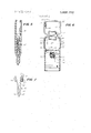
- FIG. 1 is a top perspective view of a preferred embodiment of this invention
- FIG. 2 is a rear view thereof
- FIG. 3 is a cross sectional view taken through line 3-3 of FIG. 2 with the slide in a first encased or inoperative position;
- FIG. 4 is a fragmentary side cross sectional view taken through line 44 of FIG. 2 with the slide in its operative scraping position;
- FIG. 5 is a fragmentary side cross sectional view taken through line 44 of FIG. 2 with the slide in a third outermost position enabling mounting and dismounting of a razor blade;
- FIG. 6 is a cross sectional view taken through line 66 of FIG. 3;
- FIG. 7 is a side view of the slide thereof.
- FIG. 1 a preferred embodiment of a blade scraper is shown generally at 10 in FIG. 1 and has a hand gripping casing 11 carrying a razor blade holding slide 12 in a chamber 13 at a forward section with a rear section defining a razor blade storage compartment 14.
- the hand gripping casing 10 is designed to be comfortably held in the hand of the user to allow scraping with the device held at an angle to a surface such as a window to be scraped of paint.
- the rear storage compartment 14 is formed by a bottom wall 20 with upstanding walls 21, 22, 23 and 24 with wall 24 having a cutout 25 therein. Walls 21 and 23 have upstanding ribs 26 and 27 which mate with walls 28 and 29 when the upper lid 30 is closed.
- Lid 30 is integrally hinged at 31 to rear wall 22 and provided with cutout recess 32 aligned with a recess 39 to enable hanging of the device by a hook or other means.
- a resilient locking tab 33 extends outwardly from a wall 34 of the lid and is designed to pass within the recess and be snapped against a front wall 40 of the blade holding section of the scraper.
- a finger cutout portion 41 is formed on the outside of side walls 21 and 23 so that the fingers can pass beneath the lid and pull the lid up from its locked position. The lid snaps into its closed position as shown in FIG. 1 upon applying finger pressure to the lid.
- the compartment 14 is designed to have sufficient size to store conventional single edge scraping razor blades.
- the forward section of the hand gripping casing has a front wall 40 and a rear wall 42 which is effectively an extension of wall 20.
- Side walls 43 and 44 define with the front and rear walls, the slide chamber 13 which has an opening 45 through which the slide passes to expose the razor blade knife edge 46 in the operative position of the scraper.
- Walls 40 and 42 provide surfaces 47 and 48 which are preferably parallel and on which the slide is mounted for reciprocal sliding to the positions shown in FIGs. 3-5.
- the top surface of the scraper has an upstanding beveled perimeter indicated at 48 extending therearound.
- Top wall 40 has a cutout slot 50 axially aligned along the path of travel of the slide and defining a locking cutout 51 and a second locking cutout 52 with a portion of the slot 53' defining a forward end 53 thereof beyond the locking cutout 52.
- Rear wall 42 defines a hole 54 adapted to receive a safety button 55 carried by the slide.
- the slide which holds a razor blade therein and moves it from an inoperative encased position to an operative position and beyond for exchanging the razor blade is denoted generally at 60.
- it is formed as an integral piece of a resilient plastic such as polystyrene, Delrin, acetal or the like.
- the slide has a planar rear leg 61 carrying the safety button 55 and a forward planar leg 62 carrying an actuating and locking button 63.
- Button 63 has side extensions or nibs 64 on either side thereof adapted to lock the slide in the locking cutouts 51 or 52 as desired.
- Legs 61 and 62 meet at a forward portion 65 of the slide beyond which are forwardly extending jaws 66 and 67 normally biased toward each other into touching engagement as best shown in FIG. 4.
- the jaws 66 and 67 are resiliently spread apart to firmly hold the razor blade in fixed position with respect to the slide with the blade cutting edge 46 adapted for movement along a planar path into and out of the casing as exemplified by FIGS. 3-5.
- the legs 61 and 62 are preferably molded to have a dimension such that they are spread apart in their unstressed state to a greater degree than when mounted within the slide chamber 13.
- the legs are resiliently urged against the sliding surfaces 47 and 48 with the safety button 55 urged outwardly into the hole 54 and the locking button 63 and its associated side nibs 64 urged outwardly into the cutout 51 in a first encased position of the slide as best shown in FIG. 3.
- the slide is in effect a double spring with legs 61 and 62 having a spring action directed outwardly against the surfaces 47 and 48 and the jaws 66 and 67 resiliently urged inwardly to grip and firmly hold a single edge razor blade.
- the spring action of the safety button is further enhanced by the use of an elongated notch 70 which separates a tab portion of leg 61 enabling it to bend free of the bending action of the remainder of leg portion 61 as best seen in FIG. 4.
- a corner 72 is cut out of leg 62 so that when the safety button is fully depressed the tab portion 71 can extend to the opposite surface 47 without being blocked by the opposing leg 62 as best shown in FIG. 4.
- slide 60 has a first position illustrated in FIG. 3 with the locking nibs of the locking button 63 extending through the cutout 51 at which time the safety button 55 passes through the cutout 54 together locking the razor blade 68 in the encased retracted position with the cutting edge 46 shielded by the case.
- the button 63 is depressed until the nibs 64 pass below the surface 47 and the safety button 55 is depressed sliding the slide to the position shown in FIG. 4 where the nibs are positioned in the cutout 52.
- the nibs 64 of the locking button alone provide a locking means for locking the blade in its operative position extending through the opening 45 with the blade cutting and scraping edge 46 exposed.
- FIG. 3 the locking nibs of the locking button 63 extending through the cutout 51 at which time the safety button 55 passes through the cutout 54 together locking the razor blade 68 in the encased retracted position with the cutting edge 46 shielded by the case.
- the button 63 is depressed until the nibs 64 pass below the surface 47 and the safety button 55 is
- a novel improvement in this invention comprises the use of sliding surfaces and complementary surfaces 81 on each of the nibs on either side of the button 63. These surfaces are angled at an acute angle to the plane of the razor blade travel.
- the slide 60 moves slightly rearwardly and the nibs provide complementary surfaces which tend to wedge the locking nibs into engagement along surfaces 80 and 81 pulling upwardly on surface 82 of the leg 62 and wedging it into engagement with slide surface 47 causing a wedging action which resists substantial scraping forces without causing the locking nibs to spring out of the locking cutouts.
- This feature is extremely important in the preferred embodiment since the preferred embodiment is formed of relatively soft polypropylene or other plastic material having walls of approximately 0.08 inch thick. Unless a wedge action is included, large scraping forces could tend to dislodge the blade from its locked position.
- the button 62 is again depressed to cause nibs 64 to slide along surface 47 until the button meets the forward edge 53' whereupon the razor blade holding slot between the jaws 66 and 67 are exposed enabling a single edge razor blade to be slid laterally out of the holder and a new blade positioned therein for replacement of worn out blades.
- the safety button provides a double lock which requires pressure actuation at two distinct points in order to unsheath the blade. This feature makes it difficult for young children or others to release and unsheath the blade by mistake or tampering as opposed to conventional devices which require pressure actuation at a single point.
- the locking nibs having complementary surfaces such as 80 and 81 can be employed in a wide variety of scrapers to provide a positive wedging action coacting against scraping force.
- the safety button feature can be incorporated in conventional scrapers of various kinds.
- the specific configuration of parts can vary in many cases. While the generally rectangular outline is preferred with an enlarged case or compartment section for conformity to the hand of the user, other shapes can be used. Similarly while all parts of the device are preferably formed of molded plastics, other materials can be used for portions or all of the device if desired.
- the handle can be solid or hollow at its rear without having a lid to enable storage of blades.
- Polypropylene is a preferred plastic for use for all parts of the scraper although other plastics such as polyethylene, polyvinyl acetate, tefion and the like can also be used.
- the casing has a length from the opening 45 to the rear end of 4 inches with a maximum width of 1% inches and a thickness of threeeighths inch. These dimensions can vary greatly as desired.
- a blade scraper comprising, a hand gripping casmg,
- said casing defining a chamber with first and second opposed slide surfaces and an opening to the outside of said casing
- said slide having resilient first and second spring legs biased into engagement with said surfaces respectively
- said locking means comprising first and second cutouts defined by said casing and a pressure button means constructed and arranged to be urged into said first cutout in said retracted position and said second cutout in said operative position whereby said button can be actuated by finger pressure from outside said casing to release said locking means,
- said second cutout and said button means defining complementary surfaces for engagement to cause wedge locking of said slide in said second position upon application of a scraping force to said cutting edge.
- a blade scraper in accordance with claim 6 and further comprising,
- said first and second cutouts being interconnected by a slot defined by a wall of said casing with said slot having a forward end defining a third position of said slide with said slide exposed through said opening for permitting lateral mounting of a razor blade thereon.
- a razor blade scraper comprising,
- said slide being mounted in a chamber defined by said casing with said chamber defining an opening at an end of said casing
- safety means providing a safety lock to hold said slide and blade in said first position while permitting release of said slide upon pressure actuation thereof whereby pressure must be applied to said safety means and said locking means to expose said blade.
Abstract
A blade scraper has a hand grip casing with a slide mounted in a chamber of the casing for holding a razor blade and permitting retraction of the razor blade into an inoperative position and sliding movement to an operative position with the blade in a scraping position exposed outside of the chamber. A pressure sensitive locking button acts to lock the blade in the inoperative position or the exposed position and has wedging means for tightly holding the blade in the operative position when a scraping force is applied. Preferably a safety button is interconnected with the slide so that pressure must be applied to two actuating buttons in order to expose the blade thus making it difficult for small children to accidentally place the scraper in a mode of operation dangerous for handling.
Description
Gerson et a1.
[ 1 BfLAJE ASQRAPEEL [75] Inventors: Ronald L. Gerson, Newton;
Lawrence A. Caprio, Whitman, both of Mass.
[73] Assignee: Louis M. Gerson Co., Inc.,
Middleboro, Mass.
[22] Filed: Apr. 19, 1974 [21] Appl. No.: 462,412
[52] US. Cl. 30/162, 30/169 [51] Int. Cl B26b 1/08 [58] Field of Search 30/162, 169, 320, 293, 30/335 [56] References Cited UNITED STATES PATENTS 2,404,141 7/1946 Nelson 30/162 2,601,723 7/1952 Keller i 30/162 2,754,584 7/1956 Ferguson 30/162 3,765,089 10/1973 lbata 30/162 X [111 3,855,700 [451 Dec. 24, 1974 Primary Examiner-Al Lawrence Smith Assistant ExaminerJ. C. Peters Attorney, Agent, or FirmWolf, Greenfield & Sacks [57] ABSTRACT A blade scraper has a hand grip casing with a slide mounted in a chamber of the casing for holding a razor blade and permitting retraction of the razor blade into an inoperative position and sliding movement to an operative position with the blade in a scraping position exposed outside of the chamber. A pressure sensitive locking button acts to lock the blade in the inoperative position or the exposed position and has w'edging means for tightly holding the blade in the operative position when a scraping force is applied. Preferably a safety button is interconnected with the slide so that pressure must be applied to two actuating buttons in order to expose the blade thus making it difficult for small children to accidentally place the scraper in a mode of operation dangerous for handling.
9 Claims, 7 Drawing Figures PATENTEI] UEEZ 4 I974 SHEET 1 0F 2 BLADE SCRAPER BACKGROUND OF THE INVENTION Razar blade holding scrapers have been known for many, many years. More recently, plastic body scrapers have come into use because of ease of manufacture and reduction in cost over well-known metallic handled scrapers. Such scrapers are commonly used for scraping paint and other unwanted materials from surfaces such as glass surfaces and the like.
Particularly with plastic bodied scrapers having a plastic slide holding a razor blade for movement to encased or to operative positions, locking means for holding the blade in position against the scraping forces encountered are sometimes a problem to properly design. Because of the softer nature of plastic as opposed to metal, high scraping forces sometimes causes dislodgment of the locking means and blade.
Razor blade scrapers in common usage can be inherently dangerous devices when in the hands of young children. Once the razor blade is exposed, the sharp cutting edge presents a serious hazard to unwary handlers of the device. In most known blade scrapers, it is extremely simple to move the blade from an inoperative enclosed position to its operative position as by the use of a single button or slide easily operable by young children.
SUMMARY OF THE INVENTION It is an object of this invention to provide a novel and efficient blade scraper having a slide carrying the razor blade for movement between an inoperative and operative position with good locking of the blade in the operative position to permit scraping and retention of the operative position under high scraping forces.
Still another object of this invention is to provide a blade scraper which has safety means requiring actuation of two different means to expose the blade for use and thus rendering the scraper less dangerous when handled by young children.
Still another object of this invention is to provide a blade scraper in accordance with the preceding objects which can be efficiently manufactured from plastic materials and has sufficient strength and rigidity for a wide variety of scraping applications.
According to the invention, a blade scraper has a hand gripping casing with a slide slidably mounted in the casing and having means for mounting and carrying a scraping blade having a cutting edge. The casing defines a chamber with first and second opposed slide surfaces and an opening to the outside of the casing. The slide has first and second resilient spring legs biased into engagement with the first and second slide surfaces respectively with pressure sensitive locking means for locking the slide in a first retracted position having the scraper blade carried therein wholly within the chamber and in a second operative position with the cutting edge exposed after sliding through the opening. The locking means has first and second cutouts defined by the casing and a pressure sensitive button means constructed and arranged to be urged into the first cutout in the retracted position and the second cutout in the operative position whereby the button can be actuated by finger pressure from outside the casing to release the locking means. The second cutout and the button means define complementary surfaces for engagement to cause wedge locking of the slide in the second position upon application of a scraping force to the cutting edge.
In the preferred embodiment a pressure actuated safety means provides a safety lock to hold the slide and blade in the inoperative encased position while permitting release of the slide upon pressure actuation so that pressure must be applied to the safety means and the locking means to expose the blade thus making it difficult for young children to inadvertently expose the blade.
It is an important feature of this invention that positive locking means are used to retain the blade in the operative position even under high scraping forces. This feature is a significant improvement particularly where all parts are made of molded plastic. In such cases the locking means is extremely important if sufficient strength is to be provided to prevent unwanted slippage of the slide from the operative to the inoperative position when high scraping forces are applied.
It is another feature of this invention that the blade scraper can be molded of plastic materials rapidly and inexpensively thereby minimizing cost in a high efficiency final product.
BRIEF DESCRIPTION OF THE DRAWINGS The above and other objects, features and advantages of the present invention will be better understood from a reading of the following specification in conjunction with the accompanying drawings in which:
FIG. 1 is a top perspective view of a preferred embodiment of this invention;
FIG. 2 is a rear view thereof;
FIG. 3 is a cross sectional view taken through line 3-3 of FIG. 2 with the slide in a first encased or inoperative position;
FIG. 4 is a fragmentary side cross sectional view taken through line 44 of FIG. 2 with the slide in its operative scraping position;
FIG. 5 is a fragmentary side cross sectional view taken through line 44 of FIG. 2 with the slide in a third outermost position enabling mounting and dismounting of a razor blade;
FIG. 6 is a cross sectional view taken through line 66 of FIG. 3; and
FIG. 7 is a side view of the slide thereof.
DESCRIPTION OF PREFERRED EMBODIMENTS With reference now to the drawings, a preferred embodiment of a blade scraper is shown generally at 10 in FIG. 1 and has a hand gripping casing 11 carrying a razor blade holding slide 12 in a chamber 13 at a forward section with a rear section defining a razor blade storage compartment 14.
The hand gripping casing 10 is designed to be comfortably held in the hand of the user to allow scraping with the device held at an angle to a surface such as a window to be scraped of paint. The rear storage compartment 14 is formed by a bottom wall 20 with upstanding walls 21, 22, 23 and 24 with wall 24 having a cutout 25 therein. Walls 21 and 23 have upstanding ribs 26 and 27 which mate with walls 28 and 29 when the upper lid 30 is closed. Lid 30 is integrally hinged at 31 to rear wall 22 and provided with cutout recess 32 aligned with a recess 39 to enable hanging of the device by a hook or other means. A resilient locking tab 33 extends outwardly from a wall 34 of the lid and is designed to pass within the recess and be snapped against a front wall 40 of the blade holding section of the scraper. A finger cutout portion 41 is formed on the outside of side walls 21 and 23 so that the fingers can pass beneath the lid and pull the lid up from its locked position. The lid snaps into its closed position as shown in FIG. 1 upon applying finger pressure to the lid. The compartment 14 is designed to have sufficient size to store conventional single edge scraping razor blades.
The forward section of the hand gripping casing has a front wall 40 and a rear wall 42 which is effectively an extension of wall 20. Side walls 43 and 44 define with the front and rear walls, the slide chamber 13 which has an opening 45 through which the slide passes to expose the razor blade knife edge 46 in the operative position of the scraper. Walls 40 and 42 provide surfaces 47 and 48 which are preferably parallel and on which the slide is mounted for reciprocal sliding to the positions shown in FIGs. 3-5. In the preferred embodiment, the top surface of the scraper has an upstanding beveled perimeter indicated at 48 extending therearound.
The slide which holds a razor blade therein and moves it from an inoperative encased position to an operative position and beyond for exchanging the razor blade, is denoted generally at 60. Preferably it is formed as an integral piece of a resilient plastic such as polystyrene, Delrin, acetal or the like. The slide has a planar rear leg 61 carrying the safety button 55 and a forward planar leg 62 carrying an actuating and locking button 63. Button 63 has side extensions or nibs 64 on either side thereof adapted to lock the slide in the locking cutouts 51 or 52 as desired. Legs 61 and 62 meet at a forward portion 65 of the slide beyond which are forwardly extending jaws 66 and 67 normally biased toward each other into touching engagement as best shown in FIG. 4. Upon insertion of a standard single edge razor blade such as 68, the jaws 66 and 67 are resiliently spread apart to firmly hold the razor blade in fixed position with respect to the slide with the blade cutting edge 46 adapted for movement along a planar path into and out of the casing as exemplified by FIGS. 3-5.
The legs 61 and 62 are preferably molded to have a dimension such that they are spread apart in their unstressed state to a greater degree than when mounted within the slide chamber 13. Thus when the slide is mounted within the chamber 13 as best shown in FIGS. 3-5, the legs are resiliently urged against the sliding surfaces 47 and 48 with the safety button 55 urged outwardly into the hole 54 and the locking button 63 and its associated side nibs 64 urged outwardly into the cutout 51 in a first encased position of the slide as best shown in FIG. 3.
The slide is in effect a double spring with legs 61 and 62 having a spring action directed outwardly against the surfaces 47 and 48 and the jaws 66 and 67 resiliently urged inwardly to grip and firmly hold a single edge razor blade. The spring action of the safety button is further enhanced by the use of an elongated notch 70 which separates a tab portion of leg 61 enabling it to bend free of the bending action of the remainder of leg portion 61 as best seen in FIG. 4. To further enhance this action, a corner 72 is cut out of leg 62 so that when the safety button is fully depressed the tab portion 71 can extend to the opposite surface 47 without being blocked by the opposing leg 62 as best shown in FIG. 4.
Turning now to operation of the device, slide 60 has a first position illustrated in FIG. 3 with the locking nibs of the locking button 63 extending through the cutout 51 at which time the safety button 55 passes through the cutout 54 together locking the razor blade 68 in the encased retracted position with the cutting edge 46 shielded by the case. In order to activate sliding, the button 63 is depressed until the nibs 64 pass below the surface 47 and the safety button 55 is depressed sliding the slide to the position shown in FIG. 4 where the nibs are positioned in the cutout 52. In this position the nibs 64 of the locking button alone provide a locking means for locking the blade in its operative position extending through the opening 45 with the blade cutting and scraping edge 46 exposed. As best shown in FIG. 4, a novel improvement in this invention comprises the use of sliding surfaces and complementary surfaces 81 on each of the nibs on either side of the button 63. These surfaces are angled at an acute angle to the plane of the razor blade travel. Thus when a scraping force is exerted toward the cutting edge 46 along the plane of the blade, the slide 60 moves slightly rearwardly and the nibs provide complementary surfaces which tend to wedge the locking nibs into engagement along surfaces 80 and 81 pulling upwardly on surface 82 of the leg 62 and wedging it into engagement with slide surface 47 causing a wedging action which resists substantial scraping forces without causing the locking nibs to spring out of the locking cutouts. This feature is extremely important in the preferred embodiment since the preferred embodiment is formed of relatively soft polypropylene or other plastic material having walls of approximately 0.08 inch thick. Unless a wedge action is included, large scraping forces could tend to dislodge the blade from its locked position.
In a third position of the slide shown in FIG. 5, the button 62 is again depressed to cause nibs 64 to slide along surface 47 until the button meets the forward edge 53' whereupon the razor blade holding slot between the jaws 66 and 67 are exposed enabling a single edge razor blade to be slid laterally out of the holder and a new blade positioned therein for replacement of worn out blades.
It is a feature of this invention that the safety button provides a double lock which requires pressure actuation at two distinct points in order to unsheath the blade. This feature makes it difficult for young children or others to release and unsheath the blade by mistake or tampering as opposed to conventional devices which require pressure actuation at a single point.
While a specific embodiment of this invention has been shown and described, many variations thereof are possible. For example, the locking nibs having complementary surfaces such as 80 and 81 can be employed in a wide variety of scrapers to provide a positive wedging action coacting against scraping force. Similarly the safety button feature can be incorporated in conventional scrapers of various kinds. The specific configuration of parts can vary in many cases. While the generally rectangular outline is preferred with an enlarged case or compartment section for conformity to the hand of the user, other shapes can be used. Similarly while all parts of the device are preferably formed of molded plastics, other materials can be used for portions or all of the device if desired. While a storage compartment is preferred for ease of storing spare blades, in some cases, the handle can be solid or hollow at its rear without having a lid to enable storage of blades. Polypropylene is a preferred plastic for use for all parts of the scraper although other plastics such as polyethylene, polyvinyl acetate, tefion and the like can also be used.
In the preferred embodiment, the casing has a length from the opening 45 to the rear end of 4 inches with a maximum width of 1% inches and a thickness of threeeighths inch. These dimensions can vary greatly as desired.
What is claimed is:
1. A blade scraper comprising, a hand gripping casmg,
a slide mounted in said casing and having means for mounting and carrying a scraping blade having a cutting edge,
said casing defining a chamber with first and second opposed slide surfaces and an opening to the outside of said casing,
said slide having resilient first and second spring legs biased into engagement with said surfaces respectively,
pressure actuated locking means for locking said slide in a first retracted position with a scraper blade carried therein wholly within said chamber and a second operative position with said cutting edge exposed through said opening,
said locking means comprising first and second cutouts defined by said casing and a pressure button means constructed and arranged to be urged into said first cutout in said retracted position and said second cutout in said operative position whereby said button can be actuated by finger pressure from outside said casing to release said locking means,
said second cutout and said button means defining complementary surfaces for engagement to cause wedge locking of said slide in said second position upon application of a scraping force to said cutting edge.
2. A blade scraper in accordance with claim 1 and further comprising said hand gripping casing defining a hinged blade storage compartment.
3. A blade scraper in accordance with claim 1 and further comprising said slide means for mounting and carrying said scraping blade, mounting said scraping blade in a plane for reciprocal sliding in said plane.
4. A blade scraper in accordance with claim 3 and further comprising said complementary surfaces being arranged at an angle to said plane, said surfaces being carried by said second cutout and a pair of nibs extending outwardly from said locking button means.
5. A blade scraper in accordance with claim 4 and further comprising a pressure activating safety button for providing a double lock for said slide in said first position.
6. A blade scraper in accordance with claim 5 and further comprising said safety button being mounted on a tab of said first leg with a cutout portion defined by said second leg opposed to said safety button.
7. A blade scraper in accordance with claim 6 and further comprising,
said first and second cutouts being interconnected by a slot defined by a wall of said casing with said slot having a forward end defining a third position of said slide with said slide exposed through said opening for permitting lateral mounting of a razor blade thereon.
8. A razor blade scraper comprising,
a hand gripping casing,
a slide carrying means for mounting and carrying a scraping blade,
said slide being mounted in a chamber defined by said casing with said chamber defining an opening at an end of said casing,
pressure activated locking means for locking said slide and blade in a first retracted position with said blade wholly within and encased by said chamber and a second position with said blade moved through said opening and exposed out of said chamber in an operative scraping position,
and pressure actuated safety means providing a safety lock to hold said slide and blade in said first position while permitting release of said slide upon pressure actuation thereof whereby pressure must be applied to said safety means and said locking means to expose said blade.
9. A razor blade scraper in accordance with claim 8 wherein said safety means and said locking means are positioned on opposed sides of said hand gripping casing.
Claims (9)
1. A blade scraper comprising, a hand gripping casing, a slide mounted in said casing and having means for mounting and carrying a scraping blade having a cutting edge, said casing defining a chamber with first and second opposed slide surfaces and an oPening to the outside of said casing, said slide having resilient first and second spring legs biased into engagement with said surfaces respectively, pressure actuated locking means for locking said slide in a first retracted position with a scraper blade carried therein wholly within said chamber and a second operative position with said cutting edge exposed through said opening, said locking means comprising first and second cutouts defined by said casing and a pressure button means constructed and arranged to be urged into said first cutout in said retracted position and said second cutout in said operative position whereby said button can be actuated by finger pressure from outside said casing to release said locking means, said second cutout and said button means defining complementary surfaces for engagement to cause wedge locking of said slide in said second position upon application of a scraping force to said cutting edge.
2. A blade scraper in accordance with claim 1 and further comprising said hand gripping casing defining a hinged blade storage compartment.
3. A blade scraper in accordance with claim 1 and further comprising said slide means for mounting and carrying said scraping blade, mounting said scraping blade in a plane for reciprocal sliding in said plane.
4. A blade scraper in accordance with claim 3 and further comprising said complementary surfaces being arranged at an angle to said plane, said surfaces being carried by said second cutout and a pair of nibs extending outwardly from said locking button means.
5. A blade scraper in accordance with claim 4 and further comprising a pressure activating safety button for providing a double lock for said slide in said first position.
6. A blade scraper in accordance with claim 5 and further comprising said safety button being mounted on a tab of said first leg with a cutout portion defined by said second leg opposed to said safety button.
7. A blade scraper in accordance with claim 6 and further comprising, said first and second cutouts being interconnected by a slot defined by a wall of said casing with said slot having a forward end defining a third position of said slide with said slide exposed through said opening for permitting lateral mounting of a razor blade thereon.
8. A razor blade scraper comprising, a hand gripping casing, a slide carrying means for mounting and carrying a scraping blade, said slide being mounted in a chamber defined by said casing with said chamber defining an opening at an end of said casing, pressure activated locking means for locking said slide and blade in a first retracted position with said blade wholly within and encased by said chamber and a second position with said blade moved through said opening and exposed out of said chamber in an operative scraping position, and pressure actuated safety means providing a safety lock to hold said slide and blade in said first position while permitting release of said slide upon pressure actuation thereof whereby pressure must be applied to said safety means and said locking means to expose said blade.
9. A razor blade scraper in accordance with claim 8 wherein said safety means and said locking means are positioned on opposed sides of said hand gripping casing.
Priority Applications (6)
| Application Number | Priority Date | Filing Date | Title |
|---|---|---|---|
| US00462412A US3855700A (en) | 1974-04-19 | 1974-04-19 | Blade scraper |
| CA208,016A CA1004450A (en) | 1974-04-19 | 1974-08-28 | Blade scraper |
| DE19742445756 DE2445756A1 (en) | 1974-04-19 | 1974-09-25 | SCRAPING KNIFE |
| GB1292975A GB1459986A (en) | 1974-04-19 | 1975-03-27 | Blade scraper |
| GB3249276A GB1459987A (en) | 1974-04-19 | 1975-03-27 | Blade scraper |
| CA248,329A CA996338A (en) | 1974-04-19 | 1976-03-12 | Blade scraper |
Applications Claiming Priority (1)
| Application Number | Priority Date | Filing Date | Title |
|---|---|---|---|
| US00462412A US3855700A (en) | 1974-04-19 | 1974-04-19 | Blade scraper |
Publications (1)
| Publication Number | Publication Date |
|---|---|
| US3855700A true US3855700A (en) | 1974-12-24 |
Family
ID=23836342
Family Applications (1)
| Application Number | Title | Priority Date | Filing Date |
|---|---|---|---|
| US00462412A Expired - Lifetime US3855700A (en) | 1974-04-19 | 1974-04-19 | Blade scraper |
Country Status (4)
| Country | Link |
|---|---|
| US (1) | US3855700A (en) |
| CA (1) | CA1004450A (en) |
| DE (1) | DE2445756A1 (en) |
| GB (2) | GB1459987A (en) |
Cited By (28)
| Publication number | Priority date | Publication date | Assignee | Title |
|---|---|---|---|---|
| US3964162A (en) * | 1975-06-25 | 1976-06-22 | Louis M. Gerson Co., Inc. | Blade scraper |
| US4063356A (en) * | 1975-09-10 | 1977-12-20 | Plas Plugs Limited | Hand knife |
| US4182033A (en) * | 1978-04-07 | 1980-01-08 | The Gillette Company | Scraper assembly |
| US4621425A (en) * | 1984-10-05 | 1986-11-11 | Stanley Works | Retractable knife handle |
| US4663846A (en) * | 1985-08-14 | 1987-05-12 | Takayama Sangyo Co. Ltd. | Cutter having a retractable and removable blade |
| US4778011A (en) * | 1986-07-25 | 1988-10-18 | Hutchison Marion E | Sod undercutting knife |
| US4955138A (en) * | 1989-01-13 | 1990-09-11 | Warner Manufacturing Company | Utility blade scraper |
| US5208984A (en) * | 1991-04-02 | 1993-05-11 | Lisle Corporation | Multi-purpose scraping apparatus |
| US5344424A (en) * | 1993-03-12 | 1994-09-06 | Roberts Philip L | Selectively retractable, disposable surgical knife |
| US5433004A (en) * | 1993-10-14 | 1995-07-18 | Warner Manufacturing Company | Single edge blade scraper |
| US5666732A (en) * | 1994-09-28 | 1997-09-16 | Shea; Thomas M. | Holder for use with a razor blade |
| US5713232A (en) * | 1996-04-29 | 1998-02-03 | Hodge; Bessie G. | Combined key fob and ticket scraper |
| US5996231A (en) * | 1997-08-06 | 1999-12-07 | Hyde Tools | Scraping tool with replaceable blade and controlled quick-release clamp |
| WO2000006347A1 (en) * | 1998-07-31 | 2000-02-10 | American Safety Razor Company | Wide blade scraper |
| US6061913A (en) * | 1997-07-12 | 2000-05-16 | Heinrich Konig & Co. Kg | Plastic filler spatula/plane |
| US6470574B1 (en) * | 2000-10-17 | 2002-10-29 | George E. Strumke, Jr. | Ticket scraper and coin display device |
| US20040143924A1 (en) * | 2002-01-13 | 2004-07-29 | Vermop Salmon Gmbh | Blade holder |
| US6880250B1 (en) * | 2003-06-18 | 2005-04-19 | Elias Tamez | Letter opener |
| US20050081318A1 (en) * | 2003-10-20 | 2005-04-21 | Boutilier Wayne A. | Scraper and safety sheath |
| US20100325898A1 (en) * | 2009-06-20 | 2010-12-30 | Hyde Tools, Inc. | Retractable blade scraper having a blade-storage drawer and a blade slide with upper and lower blade-clamping members |
| US20110094109A1 (en) * | 2009-10-27 | 2011-04-28 | Lian-Zhen Chiu | Scraper |
| US20120099822A1 (en) * | 2010-10-22 | 2012-04-26 | Panduit Corp. | Optical Communication Connector |
| US8201336B2 (en) | 2008-05-02 | 2012-06-19 | Olympia Tools International, Inc. | Retractable utility knife |
| US8695221B2 (en) | 2008-08-21 | 2014-04-15 | Wen Hao | Utility knife with extended travel carriage |
| US20170266826A1 (en) * | 2015-04-15 | 2017-09-21 | Ryan Kole | Razor Assembly |
| US10828793B2 (en) | 2015-04-15 | 2020-11-10 | Rk Inventions, Llc | Razor assembly |
| US11253086B1 (en) * | 2020-08-11 | 2022-02-22 | Chin-Chen Huang | Hanging structure for painting tool |
| US11493701B2 (en) | 2010-10-22 | 2022-11-08 | Panduit Corp. | Optical communications connectors |
Families Citing this family (1)
| Publication number | Priority date | Publication date | Assignee | Title |
|---|---|---|---|---|
| US3953926A (en) * | 1975-02-11 | 1976-05-04 | Kallikounis James D | Hair cutting and trimming device |
Citations (4)
| Publication number | Priority date | Publication date | Assignee | Title |
|---|---|---|---|---|
| US2404141A (en) * | 1943-12-11 | 1946-07-16 | Nelson Jennings | Razor blade holder |
| US2601723A (en) * | 1947-12-15 | 1952-07-01 | Cedarberg Mfg Company Inc | Scraper employing razor blade |
| US2754584A (en) * | 1953-02-13 | 1956-07-17 | Hyde Mfg Company | Razor blade scraper |
| US3765089A (en) * | 1971-06-16 | 1973-10-16 | Nippon Tenshashi Kk | Knife with adjustable blade |
Family Cites Families (4)
| Publication number | Priority date | Publication date | Assignee | Title |
|---|---|---|---|---|
| US2543726A (en) * | 1950-02-07 | 1951-02-27 | Richard F Landwehr | Telescoping pocketknife |
| DE1881438U (en) * | 1963-08-21 | 1963-10-24 | Henry M Unger | SCRAPER. |
| JPS5012640B1 (en) * | 1969-02-15 | 1975-05-13 | ||
| DE2149551A1 (en) * | 1970-10-05 | 1972-06-22 | Rade Popovic | Device for shaving or trimming hair |
-
1974
- 1974-04-19 US US00462412A patent/US3855700A/en not_active Expired - Lifetime
- 1974-08-28 CA CA208,016A patent/CA1004450A/en not_active Expired
- 1974-09-25 DE DE19742445756 patent/DE2445756A1/en not_active Withdrawn
-
1975
- 1975-03-27 GB GB3249276A patent/GB1459987A/en not_active Expired
- 1975-03-27 GB GB1292975A patent/GB1459986A/en not_active Expired
Patent Citations (4)
| Publication number | Priority date | Publication date | Assignee | Title |
|---|---|---|---|---|
| US2404141A (en) * | 1943-12-11 | 1946-07-16 | Nelson Jennings | Razor blade holder |
| US2601723A (en) * | 1947-12-15 | 1952-07-01 | Cedarberg Mfg Company Inc | Scraper employing razor blade |
| US2754584A (en) * | 1953-02-13 | 1956-07-17 | Hyde Mfg Company | Razor blade scraper |
| US3765089A (en) * | 1971-06-16 | 1973-10-16 | Nippon Tenshashi Kk | Knife with adjustable blade |
Cited By (41)
| Publication number | Priority date | Publication date | Assignee | Title |
|---|---|---|---|---|
| US3964162A (en) * | 1975-06-25 | 1976-06-22 | Louis M. Gerson Co., Inc. | Blade scraper |
| US4063356A (en) * | 1975-09-10 | 1977-12-20 | Plas Plugs Limited | Hand knife |
| US4182033A (en) * | 1978-04-07 | 1980-01-08 | The Gillette Company | Scraper assembly |
| US4621425A (en) * | 1984-10-05 | 1986-11-11 | Stanley Works | Retractable knife handle |
| US4663846A (en) * | 1985-08-14 | 1987-05-12 | Takayama Sangyo Co. Ltd. | Cutter having a retractable and removable blade |
| US4778011A (en) * | 1986-07-25 | 1988-10-18 | Hutchison Marion E | Sod undercutting knife |
| US4955138A (en) * | 1989-01-13 | 1990-09-11 | Warner Manufacturing Company | Utility blade scraper |
| US5208984A (en) * | 1991-04-02 | 1993-05-11 | Lisle Corporation | Multi-purpose scraping apparatus |
| US5344424A (en) * | 1993-03-12 | 1994-09-06 | Roberts Philip L | Selectively retractable, disposable surgical knife |
| US5433004A (en) * | 1993-10-14 | 1995-07-18 | Warner Manufacturing Company | Single edge blade scraper |
| US5666732A (en) * | 1994-09-28 | 1997-09-16 | Shea; Thomas M. | Holder for use with a razor blade |
| US5713232A (en) * | 1996-04-29 | 1998-02-03 | Hodge; Bessie G. | Combined key fob and ticket scraper |
| US6061913A (en) * | 1997-07-12 | 2000-05-16 | Heinrich Konig & Co. Kg | Plastic filler spatula/plane |
| US5996231A (en) * | 1997-08-06 | 1999-12-07 | Hyde Tools | Scraping tool with replaceable blade and controlled quick-release clamp |
| WO2000006347A1 (en) * | 1998-07-31 | 2000-02-10 | American Safety Razor Company | Wide blade scraper |
| US6334254B1 (en) | 1998-07-31 | 2002-01-01 | American Safety Razor | Wide blade scraper |
| US6470574B1 (en) * | 2000-10-17 | 2002-10-29 | George E. Strumke, Jr. | Ticket scraper and coin display device |
| US20040143924A1 (en) * | 2002-01-13 | 2004-07-29 | Vermop Salmon Gmbh | Blade holder |
| US6880250B1 (en) * | 2003-06-18 | 2005-04-19 | Elias Tamez | Letter opener |
| US20050081318A1 (en) * | 2003-10-20 | 2005-04-21 | Boutilier Wayne A. | Scraper and safety sheath |
| US8201336B2 (en) | 2008-05-02 | 2012-06-19 | Olympia Tools International, Inc. | Retractable utility knife |
| US8984755B2 (en) | 2008-05-02 | 2015-03-24 | Olympia Tools International, Inc. | Retractable utility knife |
| US8695221B2 (en) | 2008-08-21 | 2014-04-15 | Wen Hao | Utility knife with extended travel carriage |
| US20100325898A1 (en) * | 2009-06-20 | 2010-12-30 | Hyde Tools, Inc. | Retractable blade scraper having a blade-storage drawer and a blade slide with upper and lower blade-clamping members |
| US8291598B2 (en) * | 2009-06-20 | 2012-10-23 | Hyde Tools, Inc. | Retractable blade scraper having a blade-storage drawer and a blade slide with upper and lower blade-clamping members |
| US20110094109A1 (en) * | 2009-10-27 | 2011-04-28 | Lian-Zhen Chiu | Scraper |
| US8171646B2 (en) * | 2009-10-27 | 2012-05-08 | Goodly-Ch Enterprise Co., Ltd. | Scraper |
| US9442256B2 (en) | 2010-10-22 | 2016-09-13 | Panduit Corp. | Optical communication connector |
| US20120099822A1 (en) * | 2010-10-22 | 2012-04-26 | Panduit Corp. | Optical Communication Connector |
| KR101590891B1 (en) * | 2010-10-22 | 2016-02-02 | 팬듀트 코포레이션 | Optical communication connector |
| US11422316B2 (en) | 2010-10-22 | 2022-08-23 | Panduit Corp. | Optical communications connectors |
| US9638872B2 (en) | 2010-10-22 | 2017-05-02 | Panduit Corp. | Optical communication connector |
| US8636424B2 (en) * | 2010-10-22 | 2014-01-28 | Panduit Corp. | Optical communication connector |
| US9798094B2 (en) | 2010-10-22 | 2017-10-24 | Panduit Corp. | Optical communication connector |
| US11852874B2 (en) | 2010-10-22 | 2023-12-26 | Panduit Corp. | Optical communications connectors |
| US11822132B2 (en) | 2010-10-22 | 2023-11-21 | Panduit Corp. | Optical communications connectors |
| US11493701B2 (en) | 2010-10-22 | 2022-11-08 | Panduit Corp. | Optical communications connectors |
| US20170266826A1 (en) * | 2015-04-15 | 2017-09-21 | Ryan Kole | Razor Assembly |
| US11104019B2 (en) | 2015-04-15 | 2021-08-31 | Rk Inventions, Llc | Razor assembly |
| US10828793B2 (en) | 2015-04-15 | 2020-11-10 | Rk Inventions, Llc | Razor assembly |
| US11253086B1 (en) * | 2020-08-11 | 2022-02-22 | Chin-Chen Huang | Hanging structure for painting tool |
Also Published As
| Publication number | Publication date |
|---|---|
| GB1459987A (en) | 1976-12-31 |
| DE2445756A1 (en) | 1975-10-30 |
| GB1459986A (en) | 1976-12-31 |
| CA1004450A (en) | 1977-02-01 |
Similar Documents
| Publication | Publication Date | Title |
|---|---|---|
| US3855700A (en) | Blade scraper | |
| US3964162A (en) | Blade scraper | |
| US4531286A (en) | Carton cutting knife | |
| US6330749B1 (en) | Adjustable safety utility knife with easily removable blade holder | |
| US4646440A (en) | Replaceable blade knife | |
| US6948250B1 (en) | Retractable/disposable craft knife and blade insert therefor | |
| US20020124412A1 (en) | Utility knife tool with cover lock | |
| US3453729A (en) | Knife | |
| WO1995000300A1 (en) | Safety blade for utility knife | |
| US2291514A (en) | Hand scraper | |
| US3470781A (en) | Positive feed device for tape dispenser | |
| US5163553A (en) | Scalpel blade extractor and disposal unit | |
| US3050853A (en) | Tape dispenser | |
| US5666732A (en) | Holder for use with a razor blade | |
| US4238883A (en) | Scraper assembly with blade lock means | |
| CN212445326U (en) | Tool knife | |
| US6598301B2 (en) | Multi-purpose razor blade tool | |
| US4121329A (en) | Implement for attaching and detaching blades from a bladed tool | |
| GB1595328A (en) | Tool holder | |
| US20160288346A1 (en) | Razor Blade Holder/Scrapper | |
| US4182033A (en) | Scraper assembly | |
| US2754584A (en) | Razor blade scraper | |
| US2550757A (en) | Razor blade holder for cutting cardboard boxes | |
| IE920905A1 (en) | Hand-held tool | |
| US10179349B1 (en) | Cleaning tool |
Legal Events
| Date | Code | Title | Description |
|---|---|---|---|
| AS | Assignment |
Owner name: BAYBANK BOSTON, N.A., 175 FEDERAL STREET, BOSTON, Free format text: SECURITY INTEREST;ASSIGNOR:LOUIS M. GERSON CO., INC.;REEL/FRAME:004823/0048 Effective date: 19871120 Owner name: BAYBANK BOSTON, N.A.,MASSACHUSETTS Free format text: SECURITY INTEREST;ASSIGNOR:LOUIS M. GERSON CO., INC.;REEL/FRAME:004823/0048 Effective date: 19871120 |