US3879652A - AC solid state power controller with minimized internal power supply requirements - Google Patents
AC solid state power controller with minimized internal power supply requirements Download PDFInfo
- Publication number
- US3879652A US3879652A US387991A US38799173A US3879652A US 3879652 A US3879652 A US 3879652A US 387991 A US387991 A US 387991A US 38799173 A US38799173 A US 38799173A US 3879652 A US3879652 A US 3879652A
- Authority
- US
- United States
- Prior art keywords
- circuit
- power
- supply
- power supply
- control
- Prior art date
- Legal status (The legal status is an assumption and is not a legal conclusion. Google has not performed a legal analysis and makes no representation as to the accuracy of the status listed.)
- Expired - Lifetime
Links
Images

Classifications
-
- G—PHYSICS
- G05—CONTROLLING; REGULATING
- G05F—SYSTEMS FOR REGULATING ELECTRIC OR MAGNETIC VARIABLES
- G05F1/00—Automatic systems in which deviations of an electric quantity from one or more predetermined values are detected at the output of the system and fed back to a device within the system to restore the detected quantity to its predetermined value or values, i.e. retroactive systems
- G05F1/10—Regulating voltage or current
- G05F1/12—Regulating voltage or current wherein the variable actually regulated by the final control device is ac
- G05F1/40—Regulating voltage or current wherein the variable actually regulated by the final control device is ac using discharge tubes or semiconductor devices as final control devices
- G05F1/44—Regulating voltage or current wherein the variable actually regulated by the final control device is ac using discharge tubes or semiconductor devices as final control devices semiconductor devices only
- G05F1/45—Regulating voltage or current wherein the variable actually regulated by the final control device is ac using discharge tubes or semiconductor devices as final control devices semiconductor devices only being controlled rectifiers in series with the load
- G05F1/455—Regulating voltage or current wherein the variable actually regulated by the final control device is ac using discharge tubes or semiconductor devices as final control devices semiconductor devices only being controlled rectifiers in series with the load with phase control
-
- G—PHYSICS
- G05—CONTROLLING; REGULATING
- G05F—SYSTEMS FOR REGULATING ELECTRIC OR MAGNETIC VARIABLES
- G05F1/00—Automatic systems in which deviations of an electric quantity from one or more predetermined values are detected at the output of the system and fed back to a device within the system to restore the detected quantity to its predetermined value or values, i.e. retroactive systems
- G05F1/10—Regulating voltage or current
- G05F1/12—Regulating voltage or current wherein the variable actually regulated by the final control device is ac
- G05F1/40—Regulating voltage or current wherein the variable actually regulated by the final control device is ac using discharge tubes or semiconductor devices as final control devices
- G05F1/44—Regulating voltage or current wherein the variable actually regulated by the final control device is ac using discharge tubes or semiconductor devices as final control devices semiconductor devices only
- G05F1/445—Regulating voltage or current wherein the variable actually regulated by the final control device is ac using discharge tubes or semiconductor devices as final control devices semiconductor devices only being transistors in series with the load
Definitions
- 387391 is supplied by a power supply producing DC power and whose control and protection circuits, such as an 52 c U 323 22 3 7 353 7 7; overcurrent protection circuit a zero crossover detec- 32 323 3 tion circuit. and a control logic circuit are operative 511 1m. 01. G05f 1/56 without energization from a separate DC pp y 53 Field f Search U 307 252 252 UA 29 Rather these circuits are powered merely from the AC 307/297; 323/18. 24, 22 SC. 22 T. 9. 34-38; line and the same DC supply as for the drive circuit.
- This invention relates to power controllers for controlling the supply of power from an AC supply to a load and particularly to such power controllers suitable to applications in which size and weight must be minimized and comprising solid state rather than electromechanical components.
- the circuit portion labeled Power Supply takes AC power from line and develops DC on three separate, isolated buses. Those include a first DC bus 12 from the Power Supply to a Drive Circuit for driving the Solid State Switch.
- a second DC bus 14 is provided between the Power Supply and Drive Circuit (past drive circuits for solid state switches of two inverse parallel thyristors have typically required two isolated supplies) and also powers an Overcurrent Protection circuit, a Zero Crossover circuit, and a Control Logic circuit.
- a third DC bus 16 is provided between the Power Supply and a DC Control Circuit. For the required electrical isolation, each DC bus 12, 14, and 16 requires separate power supply components. Normally this includes a separate secondary winding for each on an AC transformer whose primary is connected to the line and also a separate rectifier and filter and regulating components.
- the present invention came about from an effort to develop a power controller whose internal power supply requirements are minimized as compared with those of the prior art.
- an AC solid state power controller having a switch whose drive circuit is supplied by a single power supply producing DC power and whose control and protection circuits, such as an overcurrent protection circuit, a zero crossover detection circuit, and a control logic circuit, are operative without energization from a separate DC supply but rather are powered merely from the AC line and the same DC supply as for the drive circuit.
- the DC control circuit requires no separate supply internal to the power controller but rather is energized solely by the applied control input signal.
- controllers internal power supply may be met by a transformer having a single secondary winding or, preferably, a transformerless configuration such as a capacitor voltage divider power supply.
- the implementation of the present invention requires the various individual circuit portions that previously required separate DC supplies be made essentially self-energized.
- self-energized is meant they develop their own power from the AC line, or from the same DC bus that powers the drive circuit, or in the case of the DC control circuit, from another available DC voltage.
- FIG. 11 is a schematic circuit diagram of an AC solid state power controller in accordance with the prior art as has been previously described;
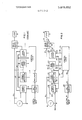
- FIG. 2 is a schematic circuit diagram of an AC solid state power controller in accordance with the present invention.
- FIG. 3 is a circuit schematic of a more detailed example of an embodiment of the present invention.
- a solid state power controller is illustrated in a one-line diagram, for controlling the supply of power from an AC supply 8 to a load 9 on AC line 10.
- the power controller includes a switch having supply and load terminals 21 and 22 connected respectively to the supply 8 and load 9 and also has at least one, in this case two, drive terminals 23 for the selective application of predetermined drive signals to alter the conduction state of the switch 20. While various switch configurations may be employed, of primary present interest in the practice of the present invention is a switch principally comprising a pair of inverse parallel thyristors.
- a drive circuit 26 is provided for applying drive signals to the switch 20 and has at least one, in this example two, output terminals 27 electrically coupled respectively to the drive terminals 23 of the switch.
- the drive circuit 26 has a control input terminal 28 for receiving control signals to which it responds as well as a power interminal 29.
- a power supply circuit 32 is provided that has input terminals 33 for connection to the AC supply and a reference potential (ground or neutral) and an output terminal 34 connected to the power input terminal of the drive circuit by DC bus 36.
- the power supply circuit 32 comprises elements for the conversion of AC power to DC power, with whatever filtering and regulation is desirable for the output power on bus 36.
- a control logic circuit 38 is provided that has an output terminal 39 connected to the control input terminal 28 of the drive circuit 26 and a power input terminal 40 connected to the output terminal of the power supply circuit by DC bus 36. Circuit 38 also has signal input terminals 41, 42, and 43.
- a plurality of additional circuits are provided for the purpose of introducing signals to the control logic circuit 38 for taking into account various circuit conditions or inputs to ultimately control the switching of the power switch 20.
- an overcurrent protection circuit 48 a zero crossover circuit 50, and a DC control circuit 52 connected, respectively, to input terminals 41, 42, and 43 of control logic circuit 38.
- the overcurrent protection circuit 48 is for the purpose of providing signals ultimately to control the conduction of the switch 20 so the load is not subjected to a damaging overcurrent.
- the zero crossover circuit 50 is to provide signals ultimately to control the conduction of the switch 20 in desired relation to zero crossovers of the waveform of the AC supply voltage as is required in the case of thyristor switches.
- the DC control circuit 52 is for'the purpose of introducing to the control logic circuit 38 an input signal upon the occurrence of an external stimulus such as the manual closing of a switch by push button or the like to set the power controller into operation initially.
- Overcurrent protection circuit 48 has an AC power input terminal 54 connected to the AC line 10 and a DC power input terminal 55 connected to bus 36. It
- Zero crossover circuit 50 has an AC power input terminal 60 connected to the AC line 10 and a DC power input terminal 61 connected to bus 36. It also has an output terminal 62connected to input terminal 42 of circuit 38.
- DC control circuit 52 requires no AC supply or connection to DC bus 36. It has an input terminal 65 for receiving a DC control signal from another part of the electrical system with which the power controller is used. It also has an output terminal 66 connected to input terminal 43 of circuit 38.
- the control logic circuit 38 normally would have additional outputs, beside that shown to the drive circuit 26, for the purpose of indicating certain conditions of the power controller. For example there is usually a trip indicator output terminal and a status indicator output terminal for connection to some indicators such as lamps for the purpose of showing occurrence of a trip of the switch 20 as well as the on or off status of the switch. These circuit portions are not shown as they may be provided as has been previously done and do not affect power supply requirements.
- FIG. 3 there is shown a detailed circuit schematic, by way of further example, of an embodiment of the present invention with the circuit portions boxed and identified by reference numerals corresponding to those of FIG. 1. It is believed that in principal part the manner of operation of the various circuit portions will be apparent to those skilled in the art. The following tabulation sets forth specific component identification that has been found suitable in successful operation of one form of the illustrated circuit.
- Solid State Switch 20 Thyristors S1 and S2 Type 2N690 Resistors R1 and R2 500 ohms (Circuit 20 can be generally characterized as comprising a pair of thyristors in inverse parallel connection.)
- Circuit 26 can be generally characterized as comprising a free-running core timed oscillator.
- circuit portion 26 The following elements shown in circuit portion 26 are to set the DC voltage level for the drive circuit from DC bus 36:
- Transistor Q4 2N55l Transistor Q7 MMCS 3498 Resistor R8 20,000 ohms Diodes D6(4) 5.6 v. Zeners Capacitor C6 0.47 mf., 50 v. Resistor R11 200,000 ohms Power Supply Circuit 32 Capacitor C3 0.39 mf., I00 v.
- This circuit can be generally characterized as a capacitor voltage divider (C3 and C4) power Supply 30 v. DC, nominal, is supplied at terminal 34 on power bus 36.
- C3 and C4 capacitor voltage divider
- Bus 63 is the DC return or common bus.
- Control Logic Circuit 38 Logic Gates G2, G3 and G4 CMOS type RCA/CD401 1 Quad NAND Resistor R 25,000 ohms Resistor R16 500,000 ohms Diode D15 1N9l4 Transistors Q8 and Q9 2N2219A Resistor R17 1 Megohm Capacitor C8 0.01mi Resistor R18 2,500 ohms Flip-Flops F1 and F2 CD4013A, dual device Capacitor C7 0.001 mf (This circuit may be generally characterized as comprising logic gates G2, G3 and G4 responsive to various inputs from the circuits 48, 50 and 52 to determine that state changing signals are applied to the drive circuit 26 at the desired times.)
- circuit portion 38 The following elements shown in circuit portion 38 are to set the DC voltage level for the control logic cir cuit from DC bus 36:
- Circuit 48 does not have direct connection with DC. bus 36 but instead gets power by wa of elements shown in control logic circuit 38.
- Zero rossover Circuit 50 Resistor R26 500,000 ohms Diode D9 1N649 Diode D10 1N914 Diode D1 1 12 V. Zener Capacitor C10 0.047 mf., 50 V. Resistor R27 250,000 ohms Logic Gates G5, G6, CMOS type RCA/CD 401 1 G7 and G8 Quad NAND Resistor R29 200,000 ohms Resistor R30 50,000 ohms Capacitor C11 250 pf.
- Circuit 50 gets its DC power off of bus 63.
- DC Control Circuit 52 Input control signal 85 6 V. DC, 10 ma. maximum Optically Coupled Diode Unit 0C2 (Circuit 52 can be generally characterized as including a differential amplifier having one input which is proportional to the control signal and another which 15 a reference level developed from the control signal. An output to 0C2 occurs only when the control signal exceeds a threshold level.)
- FIG. 3 is a presently preferred embodiment of the invention as has been successfully made and operated.
- the foregoing description will convey an understanding of the salient features of the invention and their operation without limiting the scope of invention to the exact form shown because numerous modifications in detail can be made.
- the power supply is devised, preferably, in a transformerless configuration, although alternatively it could be provided with a smaller transformer than previously required.
- the transformerless configuration shown and preferred is one that can be referred to as a capacitor voltage divider power supply and can be provided with considerable ease and compactness compared with transformer configuration.
- the two capacitors C3 and C4 divide the AC voltage to a desired level in a manner similar to that in which an autotransformer divides AC voltage.
- the rectifier comprising diodes D4 then provides full wave rectification to the desired portion which is then filtered by C5 processed to a 30 V. nominal voltage.
- a power controller for controlling the supply of power from an AC supply to a load and comprising:
- a switch having supply and load terminals and also having at least one drive terminal at which the selective application of predetermined drive signal alters the conductivity of said switch;
- a drive circuit for applying drive signals to said switch and having at least one output terminal electrically coupled, respectively, to said at least one drive terminal of said switch, said drive circuit having a control input terminal and a power input terminal;
- a power supply circuit having input terminals for connection to the AC supply and an output terminal connected to said power input terminal of said drive circuit, said power supply circuit comprising elements for the conversion of AC power to DC power on a single power bus;
- control logic circuit having an output terminal connected to said control input terminal of said drive circuit and a power input terminal connected to said output terminal of said power supply circuit;
- At least one control and protection circuit having at least one output signal terminal connected to said control logic circuit and having at least one input signal terminal connected to the AC supply, said at least one control and protection circuit being operative without energization from any DC power supply separate from that of said power supply circuit.
- said at least one control and protection circuit includes an overcurrent protection circuit for providing signals ultimately to control the conduction of said switch so the load is not subjected to damaging overcurrent.
- said at least one control and protection circuit includes a zero crossover circuit for providing signals ultimately to control the conduction of said switch in desired relation to zero crossovers of the waveform of the AC supply.
- said power supply circuit comprises a capacitor voltage divider power supply.
- said power pacitors serially connected across said input terminals, supply circuit is a transformerless power supply. and a full wave rectifier connected to rectify the volt- 6.
- said capaciage across one of said capacitors. tor-voltage divider power supply comprises a pair of ca-
Landscapes
- Engineering & Computer Science (AREA)
- Power Engineering (AREA)
- Physics & Mathematics (AREA)
- Electromagnetism (AREA)
- General Physics & Mathematics (AREA)
- Radar, Positioning & Navigation (AREA)
- Automation & Control Theory (AREA)
- Control Of Electrical Variables (AREA)
- Rectifiers (AREA)
- Control Of Voltage And Current In General (AREA)
Abstract
A power controller having a switch whose drive circuit is supplied by a power supply producing DC power and whose control and protection circuits, such as an overcurrent protection circuit, a zero crossover detection circuit, and a control logic circuit, are operative without energization from a separate DC supply. Rather these circuits are powered merely from the AC line and the same DC supply as for the drive circuit. This minimizes requirements of the controller''s internal power supply which may be met by a single transformer secondary winding or, preferably, a transformerless configuration such as a capacitor voltage divider power supply.
Description
United States Patent 11 1 1111 3,879,652 Billings Apr. 22, 1975 1 AC SOLID STATE POWER CONTROLLER 3.5l3 376 5/1970 Hajck 321/ WITH MINIMIZED I T L POWER 3.577.177 5/l97l Hewlett. Jr. 323/18 3.602.795 8/l97l Gunn r 32l/l5 SUPPLY REQUIREMENTS [75] Inventor: William W. Billings. Lima, Ohio p,-,',, Goldberg {73] Assignee: Westinghouse Electric Corporation, or F Telfer Pittsburgh Pa. 221 Filed: Aug. 13, 1913 1571 ABSTRACT A power controller having a switch whose drive circuit [2]] App! 387391 is supplied by a power supply producing DC power and whose control and protection circuits, such as an 52 c U 323 22 3 7 353 7 7; overcurrent protection circuit a zero crossover detec- 32 323 3 tion circuit. and a control logic circuit are operative 511 1m. 01. G05f 1/56 without energization from a separate DC pp y 53 Field f Search U 307 252 252 UA 29 Rather these circuits are powered merely from the AC 307/297; 323/18. 24, 22 SC. 22 T. 9. 34-38; line and the same DC supply as for the drive circuit.
3 5 1 1, 4 This minimizes requirements of the controllers internal power supply which may be met by a single trans- 5 References Cited former secondary winding or, preferably. a transform- UNITED STATES PATENTS erless configuration such as a capacitor voltage divider power supply. 3.477.0ll ll/l969 Wcstwood 321/15 3.506.852 4/!970 Dc Hart 307/252 0 6 Claims. 3 Drawing Figures B 2 54 (5O 2 SWITCH 22 :5 POWER s5 ggm s1 omvs T 53 NEUTRAL SUPPLY PROTECTION hgys 27 4'1 38 CONTROL CONT 66 437 LOGIC SIGNAL INPUT D.C. CONTROL CIRCUIT sum 2 0r 2 ONWT PATENTEUAPR22 I975 AC SOLID STATE POWER CONTROLLER WITH MINIMIZED INTERNAL POWER SUPPLY REQUIREMENTS CROSS REFERENCES This application is filed together with, and is related in subject matter to, the following commonly assigned applications of even date with the present application:
Ser. No. 387,992 by W. W. Billings and L. L. Tipton and entitled Zero Crossover Circuit; and Ser. No. 387,993 by J. T. Mitchell and W. W. Billings and entitled Overcurrent Protection Circuit for AC Systems.
Reference is also made to the following previously filed and copending application, assigned to the present assignee, that contains additional related subject matter:
Ser. No. 337,969, Filed Mar. 5, 1973, by K. C. Shuey and D. E. Baker and entitled Alternating Current Sensing Circuit and Method, now U.S. Pat No. 3,811,073, issued May 14, 1974.
BACKGROUND OF THE INVENTION This invention relates to power controllers for controlling the supply of power from an AC supply to a load and particularly to such power controllers suitable to applications in which size and weight must be minimized and comprising solid state rather than electromechanical components.
There are recognized advantages to replacing electromechanical relays and thermal overload devices with solid state power controllers for switching and protection functions in electrical distribution systems. Certain applications for such power controllers, such as in aircraft systems, have been impeded because of the complex circuitry designed to perform the required functions and the attendant cost, size, weight, heat dissipation, and unreliability inherent in circuits of the complexity proposed.
Prior AC solid state controllers have been characterized by requiring multiple internal power supplies for developing DC power from the AC line voltage. Typically, three isolated DC supplies are required and they may require separate regulation. Separate conductors are therefore required for supplying various ones of the internal circuit portions in a plurality of separate branch circuits. Shuey et al. U.S. Pat. No. 3,811,073, while not primarily directed to power supply requirements, does show a power controller of the same general type as that to which this application relates. Another source of useful background information on such power controllers is:
NAECON Proceedings, May 1971, a paper by D. E.
Baker entitled Power Controllers for Automatically Controlled Electrical Systems.
In a typical example of a solid state power controller in accordance with the type of prior art referred to, and
which is presented for illustrative purposes in FIG. 1 of this application, the following internal power supply requirements are present: The circuit portion labeled Power Supply takes AC power from line and develops DC on three separate, isolated buses. Those include a first DC bus 12 from the Power Supply to a Drive Circuit for driving the Solid State Switch. A second DC bus 14 is provided between the Power Supply and Drive Circuit (past drive circuits for solid state switches of two inverse parallel thyristors have typically required two isolated supplies) and also powers an Overcurrent Protection circuit, a Zero Crossover circuit, and a Control Logic circuit. A third DC bus 16 is provided between the Power Supply and a DC Control Circuit. For the required electrical isolation, each DC bus 12, 14, and 16 requires separate power supply components. Normally this includes a separate secondary winding for each on an AC transformer whose primary is connected to the line and also a separate rectifier and filter and regulating components.
The requirement for multiple power supplies means at the least a costly, complex power transformer that presents additional handling problems in manufacture. With the power transformer are required extra rectifying units and filters requisite for each of the individual supplies. Furthermore the development of various DC supply circuits from a single power transformer incurs some interaction between circuits that can impair performance and reliability, even though the DC supplies are nominally isolated.
SUMMARY OF THE INVENTION The present invention came about from an effort to develop a power controller whose internal power supply requirements are minimized as compared with those of the prior art.
In accordance with this invention, an AC solid state power controller is provided having a switch whose drive circuit is supplied by a single power supply producing DC power and whose control and protection circuits, such as an overcurrent protection circuit, a zero crossover detection circuit, and a control logic circuit, are operative without energization from a separate DC supply but rather are powered merely from the AC line and the same DC supply as for the drive circuit. The DC control circuit requires no separate supply internal to the power controller but rather is energized solely by the applied control input signal.
These features minimize requirements of the controllers internal power supply which may be met by a transformer having a single secondary winding or, preferably, a transformerless configuration such as a capacitor voltage divider power supply.
The implementation of the present invention requires the various individual circuit portions that previously required separate DC supplies be made essentially self-energized. By self-energized is meant they develop their own power from the AC line, or from the same DC bus that powers the drive circuit, or in the case of the DC control circuit, from another available DC voltage. By so arranging the system, there need be no separate DC power supply to the DC control circuit for energizing the system or the overcurrent protection system or the zero crossover circuit. Consequently, only a single DC supply voltage is required for all internal functions in the power controller. As a result,-therefore, the invention minimizes the amount of required components and their cost and size and further enhances the reliability of the power controller.
BRIEF DESCRIPTION OF THE DRAWING FIG. 11 is a schematic circuit diagram of an AC solid state power controller in accordance with the prior art as has been previously described;
FIG. 2 is a schematic circuit diagram of an AC solid state power controller in accordance with the present invention; and
FIG. 3 is a circuit schematic of a more detailed example of an embodiment of the present invention.
DESCRIPTION OF THE PREFERRED EMBODIMENTS Referring to FIG. 2, a solid state power controller is illustrated in a one-line diagram, for controlling the supply of power from an AC supply 8 to a load 9 on AC line 10. The power controller includes a switch having supply and load terminals 21 and 22 connected respectively to the supply 8 and load 9 and also has at least one, in this case two, drive terminals 23 for the selective application of predetermined drive signals to alter the conduction state of the switch 20. While various switch configurations may be employed, of primary present interest in the practice of the present invention is a switch principally comprising a pair of inverse parallel thyristors.
A drive circuit 26 is provided for applying drive signals to the switch 20 and has at least one, in this example two, output terminals 27 electrically coupled respectively to the drive terminals 23 of the switch. The drive circuit 26 has a control input terminal 28 for receiving control signals to which it responds as well as a power interminal 29.
A power supply circuit 32 is provided that has input terminals 33 for connection to the AC supply and a reference potential (ground or neutral) and an output terminal 34 connected to the power input terminal of the drive circuit by DC bus 36. The power supply circuit 32 comprises elements for the conversion of AC power to DC power, with whatever filtering and regulation is desirable for the output power on bus 36.
A control logic circuit 38 is provided that has an output terminal 39 connected to the control input terminal 28 of the drive circuit 26 and a power input terminal 40 connected to the output terminal of the power supply circuit by DC bus 36. Circuit 38 also has signal input terminals 41, 42, and 43.
A plurality of additional circuits are provided for the purpose of introducing signals to the control logic circuit 38 for taking into account various circuit conditions or inputs to ultimately control the switching of the power switch 20. In the typical example illustrated there are an overcurrent protection circuit 48, a zero crossover circuit 50, and a DC control circuit 52 connected, respectively, to input terminals 41, 42, and 43 of control logic circuit 38.
The overcurrent protection circuit 48 is for the purpose of providing signals ultimately to control the conduction of the switch 20 so the load is not subjected to a damaging overcurrent. The zero crossover circuit 50 is to provide signals ultimately to control the conduction of the switch 20 in desired relation to zero crossovers of the waveform of the AC supply voltage as is required in the case of thyristor switches. The DC control circuit 52 is for'the purpose of introducing to the control logic circuit 38 an input signal upon the occurrence of an external stimulus such as the manual closing of a switch by push button or the like to set the power controller into operation initially. These three circuit portions 48, 50 and 52 are examples of what will occassionally be referred to herein as at least one control and protection circuit.
also has an output terminal 56 connected to input terminal 41 of circuit 38.
Zero crossover circuit 50 has an AC power input terminal 60 connected to the AC line 10 and a DC power input terminal 61 connected to bus 36. It also has an output terminal 62connected to input terminal 42 of circuit 38.
The control logic circuit 38 normally would have additional outputs, beside that shown to the drive circuit 26, for the purpose of indicating certain conditions of the power controller. For example there is usually a trip indicator output terminal and a status indicator output terminal for connection to some indicators such as lamps for the purpose of showing occurrence of a trip of the switch 20 as well as the on or off status of the switch. These circuit portions are not shown as they may be provided as has been previously done and do not affect power supply requirements.
Referring to FIG. 3, there is shown a detailed circuit schematic, by way of further example, of an embodiment of the present invention with the circuit portions boxed and identified by reference numerals corresponding to those of FIG. 1. It is believed that in principal part the manner of operation of the various circuit portions will be apparent to those skilled in the art. The following tabulation sets forth specific component identification that has been found suitable in successful operation of one form of the illustrated circuit.
Type 806l3-%D material resistor R5 and R6 82 ohms, positive temperature coefficient Capacitors Cl and C2 0.0l mf.
(Circuit 26 can be generally characterized as comprising a free-running core timed oscillator.)
The following elements shown in circuit portion 26 are to set the DC voltage level for the drive circuit from DC bus 36:
Transistor Q4 2N55l Transistor Q7 MMCS 3498 Resistor R8 20,000 ohms Diodes D6(4) 5.6 v. Zeners Capacitor C6 0.47 mf., 50 v. Resistor R11 200,000 ohms Power Supply Circuit 32 Capacitor C3 0.39 mf., I00 v.
-Continued Capacitor C4 0.10 mf 600 v. Diodes D4 (four) 1N486A Capacitor C5 mf. 75 v.
(This circuit can be generally characterized as a capacitor voltage divider (C3 and C4) power Supply 30 v. DC, nominal, is supplied at terminal 34 on power bus 36.
The following elements shown in circuit portion 38 are to set the DC voltage level for the control logic cir cuit from DC bus 36:
Diode D5 7.6 v. Zener Resistor R7 20,000 ohms Transistor Q3 2N55l Overcurrent Protection Circuit 48 Resistors R19 and R20 0.5 ohm Resistors R21 1 10180 ohms variable Diode D8 2.7 v. Zener Resistor R23 8 ohms Optically Coupled Diode Monsanto type MCD2 Unit 0C1 Resistor R24 2 Megohms Resistor R25 10,000 ohms P.T.C. Capacitor C9 2 mf (Further description of this type of overcurrent protection circuit may be had by reference to the mentioned copending application of Mitchell and Billings,
and also to the copending application S.N.
337,969 of Shuey and Baker. Circuit 48 does not have direct connection with DC. bus 36 but instead gets power by wa of elements shown in control logic circuit 38.)
Zero rossover Circuit 50 Resistor R26 500,000 ohms Diode D9 1N649 Diode D10 1N914 Diode D1 1 12 V. Zener Capacitor C10 0.047 mf., 50 V. Resistor R27 250,000 ohms Logic Gates G5, G6, CMOS type RCA/CD 401 1 G7 and G8 Quad NAND Resistor R29 200,000 ohms Resistor R30 50,000 ohms Capacitor C11 250 pf.
(Further description of this type of zero crossover circuit may be had by reference to the mentioned copending application of Billings and Tipton.
The circuit of FIG. 3 is a presently preferred embodiment of the invention as has been successfully made and operated. The foregoing description will convey an understanding of the salient features of the invention and their operation without limiting the scope of invention to the exact form shown because numerous modifications in detail can be made.
Since only a single DC power bus 36 is required the power supply is devised, preferably, in a transformerless configuration, although alternatively it could be provided with a smaller transformer than previously required. The transformerless configuration shown and preferred is one that can be referred to as a capacitor voltage divider power supply and can be provided with considerable ease and compactness compared with transformer configuration. In this type of circuit, the two capacitors C3 and C4 divide the AC voltage to a desired level in a manner similar to that in which an autotransformer divides AC voltage. The rectifier comprising diodes D4 then provides full wave rectification to the desired portion which is then filtered by C5 processed to a 30 V. nominal voltage.
What is claimed is:
1. A power controller for controlling the supply of power from an AC supply to a load and comprising:
a switch having supply and load terminals and also having at least one drive terminal at which the selective application of predetermined drive signal alters the conductivity of said switch;
a drive circuit for applying drive signals to said switch and having at least one output terminal electrically coupled, respectively, to said at least one drive terminal of said switch, said drive circuit having a control input terminal and a power input terminal;
a power supply circuit having input terminals for connection to the AC supply and an output terminal connected to said power input terminal of said drive circuit, said power supply circuit comprising elements for the conversion of AC power to DC power on a single power bus;
a control logic circuit having an output terminal connected to said control input terminal of said drive circuit and a power input terminal connected to said output terminal of said power supply circuit;
at least one control and protection circuit having at least one output signal terminal connected to said control logic circuit and having at least one input signal terminal connected to the AC supply, said at least one control and protection circuit being operative without energization from any DC power supply separate from that of said power supply circuit.
2. The subject matter of claim 1 wherein said at least one control and protection circuit includes an overcurrent protection circuit for providing signals ultimately to control the conduction of said switch so the load is not subjected to damaging overcurrent.
3. The subject matter of claim 1 wherein said at least one control and protection circuit includes a zero crossover circuit for providing signals ultimately to control the conduction of said switch in desired relation to zero crossovers of the waveform of the AC supply.
4. The subject matter of claim 1 wherein said power supply circuit comprises a capacitor voltage divider power supply.
5. The subject matter of claim 1 wherein said power pacitors serially connected across said input terminals, supply circuit is a transformerless power supply. and a full wave rectifier connected to rectify the volt- 6. The subject matter of claim 4 wherein: said capaciage across one of said capacitors. tor-voltage divider power supply comprises a pair of ca-
Claims (6)
1. A power controller for controlling the supply of power from an AC supply to a load and comprising: a switch having supply and load terminals and also having at least one drive terminal at which the selective application of predetermined drive signal alters the conductivity of said switch; a drive circuit for applying drive signals to said switch and having at least one output terminal electrically coupled, respectively, to said at least one drive terminal of said switch, said drive circuit having a control input terminal and a power input terminal; a power supply circuit having input terminals for connection to the AC supply and an output terminal connected to said powEr input terminal of said drive circuit, said power supply circuit comprising elements for the conversion of AC power to DC power on a single power bus; a control logic circuit having an output terminal connected to said control input terminal of said drive circuit and a power input terminal connected to said output terminal of said power supply circuit; at least one control and protection circuit having at least one output signal terminal connected to said control logic circuit and having at least one input signal terminal connected to the AC supply, said at least one control and protection circuit being operative without energization from any DC power supply separate from that of said power supply circuit.
1. A power controller for controlling the supply of power from an AC supply to a load and comprising: a switch having supply and load terminals and also having at least one drive terminal at which the selective application of predetermined drive signal alters the conductivity of said switch; a drive circuit for applying drive signals to said switch and having at least one output terminal electrically coupled, respectively, to said at least one drive terminal of said switch, said drive circuit having a control input terminal and a power input terminal; a power supply circuit having input terminals for connection to the AC supply and an output terminal connected to said powEr input terminal of said drive circuit, said power supply circuit comprising elements for the conversion of AC power to DC power on a single power bus; a control logic circuit having an output terminal connected to said control input terminal of said drive circuit and a power input terminal connected to said output terminal of said power supply circuit; at least one control and protection circuit having at least one output signal terminal connected to said control logic circuit and having at least one input signal terminal connected to the AC supply, said at least one control and protection circuit being operative without energization from any DC power supply separate from that of said power supply circuit.
2. The subject matter of claim 1 wherein said at least one control and protection circuit includes an overcurrent protection circuit for providing signals ultimately to control the conduction of said switch so the load is not subjected to damaging overcurrent.
3. The subject matter of claim 1 wherein said at least one control and protection circuit includes a zero crossover circuit for providing signals ultimately to control the conduction of said switch in desired relation to zero crossovers of the waveform of the AC supply.
4. The subject matter of claim 1 wherein said power supply circuit comprises a capacitor voltage divider power supply.
5. The subject matter of claim 1 wherein said power supply circuit is a transformerless power supply.
Priority Applications (8)
| Application Number | Priority Date | Filing Date | Title |
|---|---|---|---|
| US387991A US3879652A (en) | 1973-08-13 | 1973-08-13 | AC solid state power controller with minimized internal power supply requirements |
| CA206,420A CA990793A (en) | 1973-08-13 | 1974-08-07 | Ac solid state power controller with minimized internal power supply requirements |
| IT41659/74A IT1018351B (en) | 1973-08-13 | 1974-08-09 | SOLID STATE POWER CONTROL DEVICE WITH MINIMIZED EXTERNAL POWER REQUIREMENTS |
| GB3546274A GB1428940A (en) | 1973-08-13 | 1974-08-12 | Ac solid state power controller with minimized internal power supply requirements |
| DE2438614A DE2438614A1 (en) | 1973-08-13 | 1974-08-12 | POWER REGULATOR FOR REGULATING THE POWER OUTPUT FROM AN AC VOLTAGE SOURCE TO A LOAD |
| NL7410777A NL7410777A (en) | 1973-08-13 | 1974-08-12 | FOOD CONTROL DEVICE. |
| JP49092047A JPS5952453B2 (en) | 1973-08-13 | 1974-08-13 | AC solid-state power controller with minimized internal power supply requirements |
| FR7428030A FR2241161B1 (en) | 1973-08-13 | 1974-08-13 |
Applications Claiming Priority (1)
| Application Number | Priority Date | Filing Date | Title |
|---|---|---|---|
| US387991A US3879652A (en) | 1973-08-13 | 1973-08-13 | AC solid state power controller with minimized internal power supply requirements |
Publications (1)
| Publication Number | Publication Date |
|---|---|
| US3879652A true US3879652A (en) | 1975-04-22 |
Family
ID=23532165
Family Applications (1)
| Application Number | Title | Priority Date | Filing Date |
|---|---|---|---|
| US387991A Expired - Lifetime US3879652A (en) | 1973-08-13 | 1973-08-13 | AC solid state power controller with minimized internal power supply requirements |
Country Status (8)
| Country | Link |
|---|---|
| US (1) | US3879652A (en) |
| JP (1) | JPS5952453B2 (en) |
| CA (1) | CA990793A (en) |
| DE (1) | DE2438614A1 (en) |
| FR (1) | FR2241161B1 (en) |
| GB (1) | GB1428940A (en) |
| IT (1) | IT1018351B (en) |
| NL (1) | NL7410777A (en) |
Cited By (41)
| Publication number | Priority date | Publication date | Assignee | Title |
|---|---|---|---|---|
| US4015193A (en) * | 1975-11-11 | 1977-03-29 | General Time Corporation | Firing circuit |
| US4096422A (en) * | 1975-12-03 | 1978-06-20 | E. I. Du Pont De Nemours And Company | Motor control system |
| US4121142A (en) * | 1977-09-20 | 1978-10-17 | Cincinnati Milacron Inc. | Full-wave bidirectional DC motor drive circuit |
| US4174496A (en) * | 1978-08-02 | 1979-11-13 | Rockwell International Corporation | Monolithic solid state power controller |
| EP0016646A1 (en) * | 1979-03-23 | 1980-10-01 | Westinghouse Electric Corporation | AC Solid-state circuit breaker |
| US4245184A (en) * | 1979-03-23 | 1981-01-13 | Westinghouse Electric Corp. | AC Solid-state circuit breaker |
| US4359681A (en) * | 1980-05-01 | 1982-11-16 | Westinghouse Electric Corp. | Alternating current power controller with DC transistor switching and an internal DC power supply |
| US4363064A (en) * | 1981-07-27 | 1982-12-07 | The United States Of America As Represented By The Secretary Of The Navy | Overcurrent protection system |
| US4370690A (en) * | 1981-02-06 | 1983-01-25 | Whirlpool Corporation | Vacuum cleaner control |
| US4384243A (en) * | 1980-06-20 | 1983-05-17 | Vectrol, Inc. | Energy saving motor controller |
| US4477748A (en) * | 1980-10-07 | 1984-10-16 | Thomas Industries, Inc. | Solid state ballast |
| US4558391A (en) * | 1983-02-14 | 1985-12-10 | Xerox Corporation | Capacitive discharge drive for electric stapler |
| WO1986001365A1 (en) * | 1984-08-15 | 1986-02-27 | Michael Callahan | A dimmer power stage |
| US4626698A (en) * | 1984-12-21 | 1986-12-02 | General Electric Company | Zero crossing synchronous AC switching circuits employing piezoceramic bender-type switching devices |
| US4633241A (en) * | 1984-11-20 | 1986-12-30 | General Electric Company | Method of automated in-place SCR testing |
| US4679130A (en) * | 1986-06-04 | 1987-07-07 | Superior Manufacturing & Instrument Corporation | Programmable power supply |
| US4706160A (en) * | 1986-04-14 | 1987-11-10 | The B.F. Goodrich Company | Noise tolerant fast acting optical overcurrent protector and method |
| US4710699A (en) * | 1983-10-14 | 1987-12-01 | Omron Tateisi Electronics Co. | Electronic switching device |
| US4713601A (en) * | 1985-09-26 | 1987-12-15 | The Dow Chemical Company | Power proportioning controller for solid state relays |
| US4723098A (en) * | 1980-10-07 | 1988-02-02 | Thomas Industries, Inc. | Electronic ballast circuit for fluorescent lamps |
| US4801858A (en) * | 1984-07-26 | 1989-01-31 | Pt Components, Inc. | Motor starting circuit |
| US4814931A (en) * | 1987-01-15 | 1989-03-21 | The B. F. Goodrich Company | Apparatus and method for timed-de-icing |
| US4823069A (en) * | 1984-08-15 | 1989-04-18 | Michael Callahan | Light dimmer for distributed use employing inductorless controlled transition phase control power stage |
| US4835652A (en) * | 1988-07-06 | 1989-05-30 | Westinghouse Electric Corp. | Bi-directional DC power controller with fault protection |
| US4873471A (en) * | 1986-03-28 | 1989-10-10 | Thomas Industries Inc. | High frequency ballast for gaseous discharge lamps |
| US4943761A (en) * | 1988-07-06 | 1990-07-24 | Westinghouse Electric Corp. | Current limited DC power controller |
| US4955069A (en) * | 1989-03-02 | 1990-09-04 | Ionescu Adrian F | A.C. power controller with short circuit and overload protection |
| US5045774A (en) * | 1989-12-28 | 1991-09-03 | R. Morley, Inc. | Full scale AC or DC power attenuator |
| US5181155A (en) * | 1990-08-30 | 1993-01-19 | Beg Mirza A | Overcurrent trip circuit |
| US5225765A (en) * | 1984-08-15 | 1993-07-06 | Michael Callahan | Inductorless controlled transition and other light dimmers |
| US5444214A (en) * | 1993-12-06 | 1995-08-22 | The Lincoln Electric Company | Apparatus and method for synchronizing a firing circuit for a brushless alternator rectified D. C. welder |
| US5629607A (en) * | 1984-08-15 | 1997-05-13 | Callahan; Michael | Initializing controlled transition light dimmers |
| US5932128A (en) * | 1997-02-26 | 1999-08-03 | White Consolidated Industries, Inc. | Switching control system for heating panel with leakage current cancellation |
| US5940579A (en) * | 1997-02-26 | 1999-08-17 | White Consolidated Industries, Inc. | Capacitive leakage current cancellation for heating panel |
| US6037572A (en) * | 1997-02-26 | 2000-03-14 | White Consolidated Industries, Inc. | Thin film heating assemblies |
| US6178077B1 (en) * | 1996-03-27 | 2001-01-23 | Siemens Aktiengesellschaft | Electronic branch switching device |
| US20040051512A1 (en) * | 2002-07-22 | 2004-03-18 | Asn Technology Corp. | Digitally modulated power control device |
| US7558083B2 (en) | 1997-01-24 | 2009-07-07 | Synqor, Inc. | High efficiency power converter |
| US7564702B2 (en) | 1997-01-24 | 2009-07-21 | Synqor, Inc. | High efficiency power converter |
| EP2293424A3 (en) * | 2009-09-01 | 2011-05-25 | Vetco Gray Controls Limited | AC power switching module |
| US10199950B1 (en) | 2013-07-02 | 2019-02-05 | Vlt, Inc. | Power distribution architecture with series-connected bus converter |
Families Citing this family (3)
| Publication number | Priority date | Publication date | Assignee | Title |
|---|---|---|---|---|
| JPS63126855U (en) * | 1987-02-12 | 1988-08-18 | ||
| US7007179B2 (en) | 2001-02-08 | 2006-02-28 | Honeywell International Inc. | Electric load management center |
| US7020790B2 (en) | 2001-02-08 | 2006-03-28 | Honeywell International Inc. | Electric load management center including gateway module and multiple load management modules for distributing power to multiple loads |
Citations (5)
| Publication number | Priority date | Publication date | Assignee | Title |
|---|---|---|---|---|
| US3477011A (en) * | 1967-07-20 | 1969-11-04 | Ferguson Radio Corp | Ac to dc voltage conversion circuit |
| US3506852A (en) * | 1967-03-10 | 1970-04-14 | Barber Colman Co | Method and apparatus to provide zero angle firing of a static latching switch in a noise-free electric controller |
| US3513376A (en) * | 1967-11-29 | 1970-05-19 | Westinghouse Electric Corp | High voltage to low voltage regulated inverter apparatus |
| US3577177A (en) * | 1969-06-26 | 1971-05-04 | Gen Electric | Zero-crossing silicon controlled rectifier control system |
| US3602795A (en) * | 1969-10-16 | 1971-08-31 | Ibm | Transformerless power supply |
-
1973
- 1973-08-13 US US387991A patent/US3879652A/en not_active Expired - Lifetime
-
1974
- 1974-08-07 CA CA206,420A patent/CA990793A/en not_active Expired
- 1974-08-09 IT IT41659/74A patent/IT1018351B/en active
- 1974-08-12 DE DE2438614A patent/DE2438614A1/en not_active Withdrawn
- 1974-08-12 GB GB3546274A patent/GB1428940A/en not_active Expired
- 1974-08-12 NL NL7410777A patent/NL7410777A/en not_active Application Discontinuation
- 1974-08-13 FR FR7428030A patent/FR2241161B1/fr not_active Expired
- 1974-08-13 JP JP49092047A patent/JPS5952453B2/en not_active Expired
Patent Citations (5)
| Publication number | Priority date | Publication date | Assignee | Title |
|---|---|---|---|---|
| US3506852A (en) * | 1967-03-10 | 1970-04-14 | Barber Colman Co | Method and apparatus to provide zero angle firing of a static latching switch in a noise-free electric controller |
| US3477011A (en) * | 1967-07-20 | 1969-11-04 | Ferguson Radio Corp | Ac to dc voltage conversion circuit |
| US3513376A (en) * | 1967-11-29 | 1970-05-19 | Westinghouse Electric Corp | High voltage to low voltage regulated inverter apparatus |
| US3577177A (en) * | 1969-06-26 | 1971-05-04 | Gen Electric | Zero-crossing silicon controlled rectifier control system |
| US3602795A (en) * | 1969-10-16 | 1971-08-31 | Ibm | Transformerless power supply |
Cited By (50)
| Publication number | Priority date | Publication date | Assignee | Title |
|---|---|---|---|---|
| US4015193A (en) * | 1975-11-11 | 1977-03-29 | General Time Corporation | Firing circuit |
| US4096422A (en) * | 1975-12-03 | 1978-06-20 | E. I. Du Pont De Nemours And Company | Motor control system |
| US4121142A (en) * | 1977-09-20 | 1978-10-17 | Cincinnati Milacron Inc. | Full-wave bidirectional DC motor drive circuit |
| US4174496A (en) * | 1978-08-02 | 1979-11-13 | Rockwell International Corporation | Monolithic solid state power controller |
| EP0016646A1 (en) * | 1979-03-23 | 1980-10-01 | Westinghouse Electric Corporation | AC Solid-state circuit breaker |
| US4245184A (en) * | 1979-03-23 | 1981-01-13 | Westinghouse Electric Corp. | AC Solid-state circuit breaker |
| US4359681A (en) * | 1980-05-01 | 1982-11-16 | Westinghouse Electric Corp. | Alternating current power controller with DC transistor switching and an internal DC power supply |
| US4384243A (en) * | 1980-06-20 | 1983-05-17 | Vectrol, Inc. | Energy saving motor controller |
| US4477748A (en) * | 1980-10-07 | 1984-10-16 | Thomas Industries, Inc. | Solid state ballast |
| US4723098A (en) * | 1980-10-07 | 1988-02-02 | Thomas Industries, Inc. | Electronic ballast circuit for fluorescent lamps |
| US4370690A (en) * | 1981-02-06 | 1983-01-25 | Whirlpool Corporation | Vacuum cleaner control |
| US4363064A (en) * | 1981-07-27 | 1982-12-07 | The United States Of America As Represented By The Secretary Of The Navy | Overcurrent protection system |
| US4558391A (en) * | 1983-02-14 | 1985-12-10 | Xerox Corporation | Capacitive discharge drive for electric stapler |
| US4710699A (en) * | 1983-10-14 | 1987-12-01 | Omron Tateisi Electronics Co. | Electronic switching device |
| US4801858A (en) * | 1984-07-26 | 1989-01-31 | Pt Components, Inc. | Motor starting circuit |
| US4633161A (en) * | 1984-08-15 | 1986-12-30 | Michael Callahan | Improved inductorless phase control dimmer power stage with semiconductor controlled voltage rise time |
| US5672941A (en) * | 1984-08-15 | 1997-09-30 | Callahan; Michael | Inductorless controlled transition light dimmers optimizing output waveforms |
| US5629607A (en) * | 1984-08-15 | 1997-05-13 | Callahan; Michael | Initializing controlled transition light dimmers |
| WO1986001365A1 (en) * | 1984-08-15 | 1986-02-27 | Michael Callahan | A dimmer power stage |
| US5225765A (en) * | 1984-08-15 | 1993-07-06 | Michael Callahan | Inductorless controlled transition and other light dimmers |
| US4823069A (en) * | 1984-08-15 | 1989-04-18 | Michael Callahan | Light dimmer for distributed use employing inductorless controlled transition phase control power stage |
| US4975629A (en) * | 1984-08-15 | 1990-12-04 | Michael Callahan | Inductorless controlled transition and other light dimmers |
| US4633241A (en) * | 1984-11-20 | 1986-12-30 | General Electric Company | Method of automated in-place SCR testing |
| US4626698A (en) * | 1984-12-21 | 1986-12-02 | General Electric Company | Zero crossing synchronous AC switching circuits employing piezoceramic bender-type switching devices |
| US4713601A (en) * | 1985-09-26 | 1987-12-15 | The Dow Chemical Company | Power proportioning controller for solid state relays |
| US4873471A (en) * | 1986-03-28 | 1989-10-10 | Thomas Industries Inc. | High frequency ballast for gaseous discharge lamps |
| US4706160A (en) * | 1986-04-14 | 1987-11-10 | The B.F. Goodrich Company | Noise tolerant fast acting optical overcurrent protector and method |
| US4679130A (en) * | 1986-06-04 | 1987-07-07 | Superior Manufacturing & Instrument Corporation | Programmable power supply |
| US4814931A (en) * | 1987-01-15 | 1989-03-21 | The B. F. Goodrich Company | Apparatus and method for timed-de-icing |
| US4943761A (en) * | 1988-07-06 | 1990-07-24 | Westinghouse Electric Corp. | Current limited DC power controller |
| US4835652A (en) * | 1988-07-06 | 1989-05-30 | Westinghouse Electric Corp. | Bi-directional DC power controller with fault protection |
| US4955069A (en) * | 1989-03-02 | 1990-09-04 | Ionescu Adrian F | A.C. power controller with short circuit and overload protection |
| US5045774A (en) * | 1989-12-28 | 1991-09-03 | R. Morley, Inc. | Full scale AC or DC power attenuator |
| US5181155A (en) * | 1990-08-30 | 1993-01-19 | Beg Mirza A | Overcurrent trip circuit |
| US5444214A (en) * | 1993-12-06 | 1995-08-22 | The Lincoln Electric Company | Apparatus and method for synchronizing a firing circuit for a brushless alternator rectified D. C. welder |
| US6178077B1 (en) * | 1996-03-27 | 2001-01-23 | Siemens Aktiengesellschaft | Electronic branch switching device |
| US8493751B2 (en) | 1997-01-24 | 2013-07-23 | Synqor, Inc. | High efficiency power converter |
| US7558083B2 (en) | 1997-01-24 | 2009-07-07 | Synqor, Inc. | High efficiency power converter |
| US7564702B2 (en) | 1997-01-24 | 2009-07-21 | Synqor, Inc. | High efficiency power converter |
| US9143042B2 (en) | 1997-01-24 | 2015-09-22 | Synqor, Inc. | High efficiency power converter |
| US8023290B2 (en) | 1997-01-24 | 2011-09-20 | Synqor, Inc. | High efficiency power converter |
| US6037572A (en) * | 1997-02-26 | 2000-03-14 | White Consolidated Industries, Inc. | Thin film heating assemblies |
| US5932128A (en) * | 1997-02-26 | 1999-08-03 | White Consolidated Industries, Inc. | Switching control system for heating panel with leakage current cancellation |
| US5940579A (en) * | 1997-02-26 | 1999-08-17 | White Consolidated Industries, Inc. | Capacitive leakage current cancellation for heating panel |
| US20040051512A1 (en) * | 2002-07-22 | 2004-03-18 | Asn Technology Corp. | Digitally modulated power control device |
| EP2293424A3 (en) * | 2009-09-01 | 2011-05-25 | Vetco Gray Controls Limited | AC power switching module |
| US10199950B1 (en) | 2013-07-02 | 2019-02-05 | Vlt, Inc. | Power distribution architecture with series-connected bus converter |
| US10594223B1 (en) | 2013-07-02 | 2020-03-17 | Vlt, Inc. | Power distribution architecture with series-connected bus converter |
| US11075583B1 (en) | 2013-07-02 | 2021-07-27 | Vicor Corporation | Power distribution architecture with series-connected bus converter |
| US11705820B2 (en) | 2013-07-02 | 2023-07-18 | Vicor Corporation | Power distribution architecture with series-connected bus converter |
Also Published As
| Publication number | Publication date |
|---|---|
| FR2241161B1 (en) | 1981-01-02 |
| JPS5045259A (en) | 1975-04-23 |
| IT1018351B (en) | 1977-09-30 |
| GB1428940A (en) | 1976-03-24 |
| DE2438614A1 (en) | 1975-03-06 |
| CA990793A (en) | 1976-06-08 |
| FR2241161A1 (en) | 1975-03-14 |
| NL7410777A (en) | 1975-02-17 |
| JPS5952453B2 (en) | 1984-12-19 |
Similar Documents
| Publication | Publication Date | Title |
|---|---|---|
| US3879652A (en) | AC solid state power controller with minimized internal power supply requirements | |
| US4062057A (en) | Regulated power supply having a series arrangement of inverters | |
| US3818275A (en) | Circuit interrupter including improved trip circuit using current transformers | |
| US3439251A (en) | Regulated power supply with switching transistors | |
| US3428882A (en) | Shunt-switching voltage regulated power supply | |
| US3588519A (en) | Automatic paralleling system | |
| US2734160A (en) | Electrical control systems | |
| US3921197A (en) | Direct current power converter | |
| US3818308A (en) | Inverting bridge circuit | |
| US3419790A (en) | Alternating current voltage regulator utilizing electromagnetic switch means, an autotransformer and voltage sensing means | |
| US2444458A (en) | Rectifying system | |
| US3337744A (en) | Power supply with overload and under-voltage protection circuit | |
| US2601473A (en) | Supervisory device both for comparatively small and comparatively large voltage variations | |
| US3408552A (en) | Automatic protection circuit for remediable short circuit in load | |
| US3290556A (en) | Overcurrent static relay | |
| US2495783A (en) | Load balancing system | |
| CA1175479A (en) | Multi-voltage transformer input circuits with primary reactor voltage control | |
| US3202903A (en) | Tap changing voltage regulator | |
| US2322249A (en) | Electric circuit | |
| US3348132A (en) | Automatic fail-safe dual-voltage power supply circuit | |
| US4318094A (en) | Interface device for remote control | |
| US3155847A (en) | Circuit for protecting a load circuit from initial power supply voltage transients | |
| US3417256A (en) | Regulated power supply comprising a plurality of isolated systems | |
| US2265591A (en) | Electric valve protective system | |
| US3671844A (en) | Dc power controller with static switching elements and common current feedback transformer between direct voltage source and load |