US3882482A - Optical radiant energy encoding and correlating apparatus - Google Patents
Optical radiant energy encoding and correlating apparatus Download PDFInfo
- Publication number
- US3882482A US3882482A US862625A US86262569A US3882482A US 3882482 A US3882482 A US 3882482A US 862625 A US862625 A US 862625A US 86262569 A US86262569 A US 86262569A US 3882482 A US3882482 A US 3882482A
- Authority
- US
- United States
- Prior art keywords
- code
- sections
- section
- encoded
- coded
- Prior art date
- Legal status (The legal status is an assumption and is not a legal conclusion. Google has not performed a legal analysis and makes no representation as to the accuracy of the status listed.)
- Expired - Lifetime
Links
Images


Classifications
-
- G—PHYSICS
- G01—MEASURING; TESTING
- G01S—RADIO DIRECTION-FINDING; RADIO NAVIGATION; DETERMINING DISTANCE OR VELOCITY BY USE OF RADIO WAVES; LOCATING OR PRESENCE-DETECTING BY USE OF THE REFLECTION OR RERADIATION OF RADIO WAVES; ANALOGOUS ARRANGEMENTS USING OTHER WAVES
- G01S3/00—Direction-finders for determining the direction from which infrasonic, sonic, ultrasonic, or electromagnetic waves, or particle emission, not having a directional significance, are being received
- G01S3/78—Direction-finders for determining the direction from which infrasonic, sonic, ultrasonic, or electromagnetic waves, or particle emission, not having a directional significance, are being received using electromagnetic waves other than radio waves
- G01S3/782—Systems for determining direction or deviation from predetermined direction
- G01S3/783—Systems for determining direction or deviation from predetermined direction using amplitude comparison of signals derived from static detectors or detector systems
- G01S3/7835—Systems for determining direction or deviation from predetermined direction using amplitude comparison of signals derived from static detectors or detector systems using coding masks
-
- G—PHYSICS
- G01—MEASURING; TESTING
- G01S—RADIO DIRECTION-FINDING; RADIO NAVIGATION; DETERMINING DISTANCE OR VELOCITY BY USE OF RADIO WAVES; LOCATING OR PRESENCE-DETECTING BY USE OF THE REFLECTION OR RERADIATION OF RADIO WAVES; ANALOGOUS ARRANGEMENTS USING OTHER WAVES
- G01S3/00—Direction-finders for determining the direction from which infrasonic, sonic, ultrasonic, or electromagnetic waves, or particle emission, not having a directional significance, are being received
- G01S3/78—Direction-finders for determining the direction from which infrasonic, sonic, ultrasonic, or electromagnetic waves, or particle emission, not having a directional significance, are being received using electromagnetic waves other than radio waves
- G01S3/781—Details
Definitions
- ABSTRACT Object locating apparatus including receiver optics for focussing optical radiant energy emitted from an object within its field of view onto a rotatable drum having a plurality of pseudo-random coded sections disposed along a continuous loop track, the code pattern in alternate sections being identical while those in adjacent sections are skewed and inverted relative to one another.
- Rotanon of the drum uniquely encodes the g 1 g g ig radiant energy in accordance with its position thereon 'li' l' 347 6 and a photodetector converts the encoded energy to 356/152 6 an equivalent electrical signal preparatory to correlation with a reference code for a period equal to the time required for two of the drum sections to pass [56]
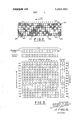
- SHEET 4 SHIFT REFERENCE C SIGNAL ENCODED SIGNAL CODE BIT OF ENCODING PERIOD VOLTAGE 12 4567891011121314 UNITS 0 aee ssh aei
- the present invention relates to optical radiant energy responsive apparatus and more particularly to means for encoding and correlating radiant energy in a manner to produce a correlation signal devoid of residuesfor the purpose of accurately determining the location of a radiating object within the field of the apparatus.
- a simple lens and photodetector configuration is capable of detecting objects but cannot precisely locate them except by means of a small field system which is scanned over a larger area. Scanning has the disadvantage of reducing the signal-to-noise ratio since the object is only momentarily within the field of the lens. It also increases the probability that a brief flash of energy will not be detected as a result of the lens being directed elsewhere at the instant the flash occurs. Consequently, object locating equipment having a large fixed field of view is generally preferred. Equipment having this characteristic typically utilizes a vidicon, photodetector matrix or coded reticle.
- Vidicons are suitable for use in the visible range but have very low sensitivity in the infrared and ultraviolet regions and poor resolution in general.
- Photodetector matrices in which leads must be affixed to each detector, are unwieldy to fabricate particularly if high resolution is required thereby necessitating the use of a very large number of extremely small detectors.
- great care must be exercised to select detectors having uniform responsivity so that the matrix does not distort the field.
- the matrix is only suitable for use in the wavelength band to which the detectors are responsive.
- Coded reticles are generally used with one or a very small number of photodetectors which therefore can be easily interchanged to accommodate the wave band of interest with good sensitivity. More recently, correlation techniques have been used in conjunction with reticles containing random or pseudo-random codes, the latter being particularly suitable for this purpose. Correlation has the advantage, when properly applied, of significantly improving the signalto-noise ratio.
- coded reticle system a plurality of pseudo-random codes are arranged such that radiation emitted from an object in the field is uniquely encoded in accordance with the position at which it is focussed on the reticle. The encoded signal is then correlated with the plurality of codes and phase shifted replicas thereof to produce an image of the radiating object.
- the present invention provides for detecting and locating optical radiant energy emitting objects by means of a relatively simple pseudo-random coding technique thereby substantially decreasing the complexity of the associated equipment. It is, however, not capable of discriminating between several objects or forming an image of even a single object and is therefore restricted to applications where it is known that only one object of interest will appear in the field of view at any instant.
- the field is focussed onto a track on a rotatable drum.
- the track contains a plurality of contiguous coded sections, each having a plurality of parallel bands disposed along the track, and the dimensions of the individual sections are adjusted to correspond to the area of the focussed field.
- the same pseudo-random code is formed in each band and in at least every other section the code in each band is shifted with respect to both the adjacent bands in the same section and the collinearly aligned bands of the contiguous sections thereby forming a code pattern in each section which is skewed with respect to the code pattern in the adjacent sections.
- the transmissivity of the code bits in each section are inverted with respect to that of the corresponding cbde bits in the adjacent sections.
- This arrangement assures that rotation of the drum imparts a unique code to optical energy focussed on the track in accordance with its position thereon.
- the encoded optical signal is converted to an equivalently encoded electrical signal by means of a photodetector positioned in back of the track and is then applied to a correlator unit, comprising coincidence detectors and integrators, wherein it is compared with a code from a reference generator.
- the reference code which is synchronized with the signal code, is the same as the code formed in each band of the coded sections on the drum and is repeated once to produce a code length equal to the length of two code sections so that the correlation period is equal to the time required for two coded sections to pass any given point in the focal plane of the receiver.
- each signal bit is generated, it is compared simultaneously with all the reference code bits and for each succeeding bit the reference code is shifted one bit thereby providing the phase shifts required between the signal and reference codes for performing the correlation.
- additional data processing equipment can be added to achieve background suppression and to provide for locating continuously radiating objects.
- FIG. 1 is a partial perspective drawing of a flash sensor apparatus constructed in accordance with the principles of the present invention
- FIG. 2 is a pictorial representation of adjacent coded sections used in the flash sensor apparatus of FIG. 1;
- FIG. 3 is a table indicating the signal amplitude at the output of the coincidence detectors and associated integrators used in the correlator of the flash sensor for discrete positions of the code pattern of FIG. 2 relative to the field of the sensor when optical radiation is incident on a predetermined position of the coded sections;
- FIG. 4 depicts the code pattern of FIG. 2 shifted with respect to the field of the optical receiver of the flash sensor
- FIG. 5 is a table indicating the signal amplitude at the output of the various detectors and associated integrators for discrete positions of the code pattern of FIG. 4 relative to the field of the sensor when optical radiation is incident thereon at the predetermined position;
- FIG. 6 is a table indicating the signal amplitude at the output of the various detectors and associated integrators when optical radiation is incident at a different position on the coded sections of FIG. 2;
- FIG. 7 depicts an alternative code pattern which is also suitable for use in the flash sensor.
- FIG. 8 is a table indicating the signal amplitude at the output of the various detectors and associated integrators for discrete positions of the code pattern of FIG. 7 relative to the field of the sensor when optical radiation is incident thereon at a predetermined position.
- each coded section includes a pseudorandom code pattern represented by clear and shaded segments 16 and 17 (bits) which are respectively relatively more transparent and opaque to the wavelength of interest, the code patterns of alternate sections being identical while those in adjacent sections are skewed and inverted relative to one another.
- Condenser lens 18 positioned behind the track collects the encoded light and directs it onto photodetector 19 wherein it is converted to an equivalent electrical signal of discrete voltage levels. It will be apparent to those skilled in the art that the condenser lens may be dispensed with in some cases, as for example, where the field of view is sufficiently small so that a photodetector having uniform responsivity over the area of its sensitive surface can be positioned immediately in back of the track.
- Tne encoded signal at the output of the photodetector is applied through amplifier 21 to background suppressor 22 and filter 23.
- Filter 23 has a low frequency bandpass which is responsive to the envelope 24 of the encoded signal.
- the filter can be made to respond to the slope of the envelope of the encoded signal so as to commence a data processing sequence at the half power point 25 or any other suitable level of the beacon pulses.
- a level detector can be used in place of the filter but the slope detector is preferred in order to reduce the likelihood of responding to large amplitude noise pulses.
- a trigger signal is provided at the output of the filter for application to background suppressor 22.
- gate 26 in the background suppressor opens to permit the amplified encoded signal from photodetector 19 to pass into delay line 27.
- counter 28 is set to count synchronizing pulses obtained through differentiator 29 from photodetector 30 which operates in conjunction with light source 31 and synchronizing track 32 containing alternate transparent and opaque segments 33 and 34 having a length equal to that of the pseudorandom code bits.
- gate 26 is closed by a signal from counter 28 which measures the period by counting the synchronizing pulses.
- the encoding period contains fourteen bits whereby fifteen pulses are applied to the counter thereby assuring that the count commences at the instant the filter provides a trigger signal irrespective of whether the synchronizing pulses are at their high or low level at that particular instant. Thereafter, fourteen differentiated pulses are counted to mark the end of each successive encoding period.
- the counter also provides a signal at the end of every period on lead 35 to clear the integrators 336 315, in correlator 37 in readiness for performing a correlation in a subsequent period.
- the encoding period as determined by the length of the coded sections and the rotational rate of the drum, can be adjusted to correspond to the length of the pulse.
- the encoding period is made equal to the separation of two discrete points such as the half power points of a single pulse, In this instance, the encoded signal at the output of photodetector 19 will still contain data relating to the flashing pulse during the next period.
- the information in one encoding period containing only the background exclusive of the signal must be subtracted from the information in another period which contains both the background and the signal.
- the signal in delay line 27 need be delayed for only one encoding period before correlation is commenced.
- gate 38 is opened for one period by a signal from counter 28 to permit the encoded signal from photodetector 19 to be compared in differential amplifier 39 with the encoded signal from delay line 27.
- a serial comparison of the successive bits in the delayed and instant encoded signals provides a signal at the output of the differential amplifier which contains information relating only to the signal of interest. This assumes, of
- the series of pulses at the output of the differential amplifier are applied in parallel to coincidence detectors 41,, to 41,, in correlator 37 wherein they are compared with the reference code pulses obtained on leads 42,, to 42, from reference code generator 43 which is synchronized with the encoded signals by means of the synchronizing pulses applied thereto on lead 44 from photodetector 30.
- the coincidence detectors produce positive pulses when the reference and signal bits are of the same polarity and negative pulses when the reference and signal bits are of opposite polarity.
- the output pulses of the respective coincidence detectors are applied to associated integrators which sum the signals applied thereto and provide a correlation signal on output terminals 46,, to 46,, which connect to readout devices (not shown).
- the delay and subtract functions of the background suppressor can be eliminated and the encoded signal at the output of photodetector 19 can be fed directly to the correlator for comparison with the reference code.
- the encoding and correlating apparatus can also be used for applications in which the energy emitted from a radiating object of interest is fairly uniform for several or more encoding periods. In this case, the background suppressor will not be needed if the background is uniform, and the filter will not be required since a correlation sequence can be initiated at any arbitrary point such as the beginning of a coded section.
- two coded sections and 15 each comprise a plurality of bands 51,, to 51, and 52,, to 52;, respectively, running in the direction of track 11 with the corresponding bands being collinearly aligned.
- the same pseudo-random code is formed in each band of both sections by means of clear and shaded segments which are relatively more transparent and opaque respectively to optical radiant energy lying in the waveband of interest.
- a seven-bit code is illustrated for simplicity of description but it should be understood that the code length will be selected in accordance with the resolution and field of view that is required.
- the illustrated code is of the form but as indicated, the code in band 51, is shifted to the left by one bit so that the code has the designated form beginning at lateral resolution element G and continuing in elements A through F.
- the code in band 51 has been shifted to the left by two bits so that the code has the designated form beginning at lateral resolution element F and continuing first in element G and then elements A through E.
- the code in each band of section 15 is the inverse of the code in section 15, and therefore has the form ln band 52,, corresponding to band 51,, of section 15,, the code is shifted one bit to the right so it has the indicated form beginning at lateral resolution element B and continuing first through element G and ending in element A.
- the code in band 52 is shifted two bits to the right and so on with the code in each band being shifted successively one bit to the right.
- the code patterns in adjacent sections are skewed relative to one another whereby corresponding code segments are located at different lateral resolution elements.
- the corresponding code segments are inverted, code segments X and X in section 15 for instance, being opaque while segments Y and Y in section 15 are transparent.
- each encoding period will begin at that time and continue as code band 52 in section 15 and the first six bits of code band 53,, in section 15 move past resolution element G in the direction of arrow 54.
- the code pattern in section 15 is identical to that in section 15 so each encoding period always includes two phase shifted replicas of the code, one being inverted with respect to the other, irrespective of both the position of the signal radiation on the coded sections and the instant that it appears thereon.
- section 15, since the code patterns in alternate sections are identical, section 15,,
- the reference code is of the form at the instant section 15 is completely within the field of the receiver optics. This code is simplya repetition of the code which is formed with different phase shifts in each band of one set of alternate sections on the drum. As each signal bit is generated, it is compared in the coincidence detectors with the reference code bits which are produced simultaneously at the fourteen output terminals of the reference generator. For each succeeding signal code bit, however, the reference code is shifted one bit before the comparison is made in order to provide the plurality of phase shifts required to correlate signal and reference codes.
- the respective coincidence detectors provide voltage pulses at their output terminals of either positive or negative polarity depending upon whether the polarities of the signal and reference code bits are identical or opposite.
- the second group of integrators (36,, to 36 the corresponding integrators, namely, 36,- and 36, also have respectively +8 and 8 voltage units at their output terminals while the voltage output of the others is zero.
- the second group of integrators is redundant and need be used only for the purpose of verification since the first group uniquely defines the location of the radiating object in the field. Therefore, the radiating object focussed on resolution element A is characterized by the and voltages at the output of integrators 36,, and 36 Now assume that the radiating object is once again located in the field at a position which results in it being focussed on resolution element A in code band 51,, but further assume that the correlation period does not commence until such time as the coded sections are positioned as indicated in FIG.
- the code segments of the skewed code patterns can also be formed by lineal, diagonally oriented bars of alternating transparency and opacity. Moreover, it is not necessary for the code to be skewed in all sections. The essential requirement is that the code pattern in at least every other section must be skewed with respect to the track but in the remaining sections the code in the individual bands may be in phase with one another, as indicated in FIG. 7 wherein the code patterns in sections 56, and 56 are skewed while those in sections 56 and 56, are straight.
- the signal code in one-half of the encoding period must not be equal and opposite to that in the other half. It will be readily appreciated that if this condition existed, the voltage output of all the integrators would be zero and there would be no indication that an object was present in the field. This is the reason why the number of segments in each row oriented normal to the direction of the track must be at least one less than the number of segments extending along the track in each coded section. Moreover, it is not necessary for the shift to be uniform from band to band in a given coded section. It is only required that the code in collinearly aligned bands of adjacent sections be shifted by different amounts within their respective sections in order to avoid ambiguity.
- An optical encoder comprising a member having a continuous loop track including at least two coded sections each having a plurality of bands disposed along the track with each band containing the same pseudo-random code formed by means of segments respectively relatively more transparent and opaque to optical radiant energy, the transmissivity of the code segments in one section being inverted with respect to the corresponding code segments in the other section and the codes in the bands of at least one of the sections being shifted relative to one another whereby the code patterns of the respective sections are skewed relative to one another.
- the apparatus of claim 5 further comprising optical means positioned adjacent said member for focussing energy radiated from an object in its field of view onto the continuous loop track within an area equal to the areal dimensions of a coded section,
- a photodetector positioned relative to said member to receive the encoded energy transmitted through the coded sections and convert it to an equivalent encoded electrical signal.
- the apparatus of claim 6 further comprising a condenser lens positioned intermediate the coded sections and the photodetector to collect the encoded energy and directit onto the photodetector.
- the correlation period is equal to the period of the encoded electrical signal and the reference code generator comprises means for shifting the reference codeone bit in a prescribed direction as each bit of the encoded signal is generated, and further including means for synchronizing the reference code with the encoded signal.
- the correlating means includes a plurality of coincidence detectors and a plurality of integrators, each integrator being connected to the output terminals of a corresponding coincidence detector which operates to determine similarity and dissimilarity of the synchronous reference code and encoded electrical signal bits applied to its input terminals and the totality of coincidence detectors being equal in number to the number of code segments in each band of a coded section.
Abstract
Object locating apparatus including receiver optics for focussing optical radiant energy emitted from an object within its field of view onto a rotatable drum having a plurality of pseudo-random coded sections disposed along a continuous loop track, the code pattern in alternate sections being identical while those in adjacent sections are skewed and inverted relative to one another. Rotation of the drum uniquely encodes the radiant energy in accordance with its position thereon and a photodetector converts the encoded energy to an equivalent electrical signal preparatory to correlation with a reference code for a period equal to the time required for two of the drum sections to pass through the field.
Description
United States Patent Green et al.
[ OPTICAL RADIANT ENERGY ENCODING AND CORRELATING APPARATUS Inventors: Benjamin W. Green, Achuza, Haifa,
Israel; Richard E. Roble, Commack; Irving Roth, Williston Park, both of US. Cl 340/347 P; 250/570; 356/152 May 6, 1975 [57] ABSTRACT Object locating apparatus including receiver optics for focussing optical radiant energy emitted from an object within its field of view onto a rotatable drum having a plurality of pseudo-random coded sections disposed along a continuous loop track, the code pattern in alternate sections being identical while those in adjacent sections are skewed and inverted relative to one another. Rotanon of the drum uniquely encodes the g 1 g g ig radiant energy in accordance with its position thereon 'li' l' 347 6 and a photodetector converts the encoded energy to 356/152 6 an equivalent electrical signal preparatory to correlation with a reference code for a period equal to the time required for two of the drum sections to pass [56] References Cited through the field- UNITED STATES PATENTS 3,216,004 1l/l965 Herriot 340/347 P 12 Clams, 8 Drawmg Flgures l M 1| II 143 22 i 420 i can I f 13 u EtTcKsRouND SET I SUPPRESSOR 2 12 30 I ERE lll l li ToR COUNTER v AMPLIFlER GATE 26-/ |F 5 OPEN 21 12 OPEN GATE TRIGGER FILTER L COINCIDENOE ,osrzcroas I 410 To 41n OORRELATOR ZZM INTEGRATORS i 360 TO sen I PAIENIED w M SHEET ABCDEFGA'B'C'D'E'F'G SHIFT CODE BIT OF ENCODING PERIOD 7 8 REFERENCE SIGNAL ENOODED SIGNAL VOLTAGE 2 3 4 5 6 9 1O 11 12 13 14 UNITS wmmfl 166 mokomhmo mozmo oz .00
I/VVE/VTORS BENJ/IMl/V W. GREEN R/CHARD E. ROBLE ByIRl/l/VG ROTH FIG.3.
A TTOR/VEY PATENTED 6 I975 sum 3 COINCIDENGE DETECTOR b-b l-- H FIG.5.
VOLTAGE UN ITS V l NTEGRATOR ael I/Vl/E/V TORS BE/VJAM/A/ W. GREEN RICHARD E. ROBLE IRV/IVG ROTH AT OR/VE) PATENTED 5W5 3.882.482
I/Vl/E/VTORS BENJAMIN W. GREE/V RICHARD E. ROBLE [RV/N6 ROTH AT ORA/E) INTEGRATOR PAH-1m n m slrs SHEET FIG.'7.
SHIFT REFERENCE SIGNAL ENCODED S1GNAL VOLTAGE CODE BlT OF ENCODlNG PERIOD moh wmvwkz N O b C d e f h l k I m n Mb HF. 6 6 6 6 6 6 6 6 6 6 6 6 6 6 L 3 3 3 3 3 3 3 3 3 3 3 3 3 3 m M 8 N T 8 E W I V N N E D MR H m C n Mm 2 1 1- 1 0 1 Q 9 8 8 o 1 G I 6 F. 5 4 3 2 1. G b C d 6 f g h l l. .K m n 1- 1. 1 1- 1 1 1 1 1 1. 1. 1. 1. 1 4 4 4 4 4 4 4 4 4 4 4 4 4 4 mokomkmo mozmeozao IRVING ROTH OPTICAL RADIANT ENERGY ENCODING AND CORRELATING APPARATUS BACKGROUND OF THE INVENTION The present invention relates to optical radiant energy responsive apparatus and more particularly to means for encoding and correlating radiant energy in a manner to produce a correlation signal devoid of residuesfor the purpose of accurately determining the location of a radiating object within the field of the apparatus.
Various techniques have been developed in the prior art for detecting, locating and imaging objects by responding to the energy radiated from them and for discriminating the objects from their background. A simple lens and photodetector configuration is capable of detecting objects but cannot precisely locate them except by means of a small field system which is scanned over a larger area. Scanning has the disadvantage of reducing the signal-to-noise ratio since the object is only momentarily within the field of the lens. It also increases the probability that a brief flash of energy will not be detected as a result of the lens being directed elsewhere at the instant the flash occurs. Consequently, object locating equipment having a large fixed field of view is generally preferred. Equipment having this characteristic typically utilizes a vidicon, photodetector matrix or coded reticle. Each has its relative advantages and disadvantages. Vidicons are suitable for use in the visible range but have very low sensitivity in the infrared and ultraviolet regions and poor resolution in general. Photodetector matrices, in which leads must be affixed to each detector, are unwieldy to fabricate particularly if high resolution is required thereby necessitating the use of a very large number of extremely small detectors. Moreover, great care must be exercised to select detectors having uniform responsivity so that the matrix does not distort the field. In addition, the matrix is only suitable for use in the wavelength band to which the detectors are responsive.
Coded reticles, on the other hand, are generally used with one or a very small number of photodetectors which therefore can be easily interchanged to accommodate the wave band of interest with good sensitivity. More recently, correlation techniques have been used in conjunction with reticles containing random or pseudo-random codes, the latter being particularly suitable for this purpose. Correlation has the advantage, when properly applied, of significantly improving the signalto-noise ratio. In one prior art coded reticle system a plurality of pseudo-random codes are arranged such that radiation emitted from an object in the field is uniquely encoded in accordance with the position at which it is focussed on the reticle. The encoded signal is then correlated with the plurality of codes and phase shifted replicas thereof to produce an image of the radiating object. As a result of the cross-correlation, that is, the comparison of the encoded signal with other codes, residues are produced in the correlation output in the form of false images which are usually of lower intensity than the object image. The problem, however, is that it cannot be determined whether the additional images are caused by the correlation process or are in fact the images of additional objects located in the field. In another prior art coded reticle correlation system, the foregoing problem is eliminated by using a single code in a plurality of tracks, the code in each track being shifted with respect to the adjacent tracks by an amount equal to the width of the field of view at the focal plane of the system and a sufficient number of tracks being provided 'so that a complete code lies within the field. Since only one code is used, crosscorrelation residues are eliminated and the ambiguities normally associated with auto-correlation, that is, the comparison of one code with itself and phase shifted replicas thereof, are eliminated as a result of using a pseudo-random code in the prescribed manner. Both of these systems require rather complex encoding mechanisms and comparatively elaborate equipment for performing the necessary data processing.
SUMMARY OF THE INVENTION The present invention provides for detecting and locating optical radiant energy emitting objects by means of a relatively simple pseudo-random coding technique thereby substantially decreasing the complexity of the associated equipment. It is, however, not capable of discriminating between several objects or forming an image of even a single object and is therefore restricted to applications where it is known that only one object of interest will appear in the field of view at any instant.
In a preferred embodiment of the present invention, designed for locating a flashing object, the field is focussed onto a track on a rotatable drum. The track contains a plurality of contiguous coded sections, each having a plurality of parallel bands disposed along the track, and the dimensions of the individual sections are adjusted to correspond to the area of the focussed field. The same pseudo-random code is formed in each band and in at least every other section the code in each band is shifted with respect to both the adjacent bands in the same section and the collinearly aligned bands of the contiguous sections thereby forming a code pattern in each section which is skewed with respect to the code pattern in the adjacent sections. In addition, the transmissivity of the code bits in each section are inverted with respect to that of the corresponding cbde bits in the adjacent sections. This arrangement assures that rotation of the drum imparts a unique code to optical energy focussed on the track in accordance with its position thereon. The encoded optical signal is converted to an equivalently encoded electrical signal by means of a photodetector positioned in back of the track and is then applied to a correlator unit, comprising coincidence detectors and integrators, wherein it is compared with a code from a reference generator. The reference code, which is synchronized with the signal code, is the same as the code formed in each band of the coded sections on the drum and is repeated once to produce a code length equal to the length of two code sections so that the correlation period is equal to the time required for two coded sections to pass any given point in the focal plane of the receiver. As each signal bit is generated, it is compared simultaneously with all the reference code bits and for each succeeding bit the reference code is shifted one bit thereby providing the phase shifts required between the signal and reference codes for performing the correlation. As will be explained further hereinafter, additional data processing equipment can be added to achieve background suppression and to provide for locating continuously radiating objects.
BRIEF DESCRIPTION OF THE DRAWINGS FIG. 1 is a partial perspective drawing of a flash sensor apparatus constructed in accordance with the principles of the present invention;
FIG. 2 is a pictorial representation of adjacent coded sections used in the flash sensor apparatus of FIG. 1;
FIG. 3 is a table indicating the signal amplitude at the output of the coincidence detectors and associated integrators used in the correlator of the flash sensor for discrete positions of the code pattern of FIG. 2 relative to the field of the sensor when optical radiation is incident on a predetermined position of the coded sections;
FIG. 4 depicts the code pattern of FIG. 2 shifted with respect to the field of the optical receiver of the flash sensor;
FIG. 5 is a table indicating the signal amplitude at the output of the various detectors and associated integrators for discrete positions of the code pattern of FIG. 4 relative to the field of the sensor when optical radiation is incident thereon at the predetermined position;
FIG. 6 is a table indicating the signal amplitude at the output of the various detectors and associated integrators when optical radiation is incident at a different position on the coded sections of FIG. 2;
FIG. 7 depicts an alternative code pattern which is also suitable for use in the flash sensor; and
FIG. 8 is a table indicating the signal amplitude at the output of the various detectors and associated integrators for discrete positions of the code pattern of FIG. 7 relative to the field of the sensor when optical radiation is incident thereon at a predetermined position.
DESCRIPTION OF THE PREFERRED EMBODIMENT Referring to FIG. 1, optical radiation propagating through the entrance aperture of receiver optics 10 is focussed onto track 11 on the curved surface of drum 12 which is rotatable about axis 13 by means of motor 14. The areal dimensions of individual coded sections 15 disposed in contiguous relationship around the track are equal to the dimensions of the focussed field of the receiver optics. As will be explained subsequently in greater detail, each coded section includes a pseudorandom code pattern represented by clear and shaded segments 16 and 17 (bits) which are respectively relatively more transparent and opaque to the wavelength of interest, the code patterns of alternate sections being identical while those in adjacent sections are skewed and inverted relative to one another. As the drum rotates, optical radiation focussed on the track is intermittently transmitted therethrough whereupon it is uniquely encoded in accordance with the position at which it intercepts the track which in turn depends upon the location of the radiation emitting object in the field of the receiver. Condenser lens 18 positioned behind the track collects the encoded light and directs it onto photodetector 19 wherein it is converted to an equivalent electrical signal of discrete voltage levels. It will be apparent to those skilled in the art that the condenser lens may be dispensed with in some cases, as for example, where the field of view is sufficiently small so that a photodetector having uniform responsivity over the area of its sensitive surface can be positioned immediately in back of the track.
Tne encoded signal at the output of the photodetector is applied through amplifier 21 to background suppressor 22 and filter 23. Filter 23 has a low frequency bandpass which is responsive to the envelope 24 of the encoded signal. Thus, if the radiating object in the field is, for instance, an airport beacon flashing on and off with a known rise time and duration, the filter can be made to respond to the slope of the envelope of the encoded signal so as to commence a data processing sequence at the half power point 25 or any other suitable level of the beacon pulses. A level detector can be used in place of the filter but the slope detector is preferred in order to reduce the likelihood of responding to large amplitude noise pulses. In any event, when an optical signal having the appropriate characteristics is received, a trigger signal is provided at the output of the filter for application to background suppressor 22. Upon receiving the trigger signal, gate 26 in the background suppressor opens to permit the amplified encoded signal from photodetector 19 to pass into delay line 27. Simultaneously, counter 28 is set to count synchronizing pulses obtained through differentiator 29 from photodetector 30 which operates in conjunction with light source 31 and synchronizing track 32 containing alternate transparent and opaque segments 33 and 34 having a length equal to that of the pseudorandom code bits. At the end of an encoding period, which corresponds to the time required for a length of track equal to the length of two code sections to traverse the signal radiation focussed thereon, gate 26 is closed by a signal from counter 28 which measures the period by counting the synchronizing pulses. In the case of a seven-bit pseudo-random code, for example, the encoding period contains fourteen bits whereby fifteen pulses are applied to the counter thereby assuring that the count commences at the instant the filter provides a trigger signal irrespective of whether the synchronizing pulses are at their high or low level at that particular instant. Thereafter, fourteen differentiated pulses are counted to mark the end of each successive encoding period. The counter also provides a signal at the end of every period on lead 35 to clear the integrators 336 315, in correlator 37 in readiness for performing a correlation in a subsequent period.
If the time duration of a flashing pulse is known, the encoding period, as determined by the length of the coded sections and the rotational rate of the drum, can be adjusted to correspond to the length of the pulse. On the other hand, if the length of the flashing pulses is not known, the encoding period is made equal to the separation of two discrete points such as the half power points of a single pulse, In this instance, the encoded signal at the output of photodetector 19 will still contain data relating to the flashing pulse during the next period. In order to discriminate the signal of interest, namely, the flashing pulse, from the background observed by the optical receiver, the information in one encoding period containing only the background exclusive of the signal must be subtracted from the information in another period which contains both the background and the signal. Thus, if it is known that the flashing pulse will continue beyond its second half power point for only a fraction of a period, the signal in delay line 27 need be delayed for only one encoding period before correlation is commenced. Thereafter, gate 38 is opened for one period by a signal from counter 28 to permit the encoded signal from photodetector 19 to be compared in differential amplifier 39 with the encoded signal from delay line 27. A serial comparison of the successive bits in the delayed and instant encoded signals provides a signal at the output of the differential amplifier which contains information relating only to the signal of interest. This assumes, of
course, that the background data remains substantially constant for at least several encoding periods and further that balanced gain is maintained for the signals applied to both input terminals of the differential amplifier.
The series of pulses at the output of the differential amplifier are applied in parallel to coincidence detectors 41,, to 41,, in correlator 37 wherein they are compared with the reference code pulses obtained on leads 42,, to 42, from reference code generator 43 which is synchronized with the encoded signals by means of the synchronizing pulses applied thereto on lead 44 from photodetector 30. The coincidence detectors produce positive pulses when the reference and signal bits are of the same polarity and negative pulses when the reference and signal bits are of opposite polarity. The output pulses of the respective coincidence detectors are applied to associated integrators which sum the signals applied thereto and provide a correlation signal on output terminals 46,, to 46,, which connect to readout devices (not shown).
For applications where it is known that the radiating object will appear against a uniform background, the delay and subtract functions of the background suppressor can be eliminated and the encoded signal at the output of photodetector 19 can be fed directly to the correlator for comparison with the reference code. The encoding and correlating apparatus can also be used for applications in which the energy emitted from a radiating object of interest is fairly uniform for several or more encoding periods. In this case, the background suppressor will not be needed if the background is uniform, and the filter will not be required since a correlation sequence can be initiated at any arbitrary point such as the beginning of a coded section. This can be accomplished for instance, by means of a light source 47, a transparent segment 48 aligned with a coded section on the drum and a photodetector 49 where the signal at the output of the photodetector is utilized to control commencement of the correlation period. On the other hand, if the background is non-uniform, it will be possible to discriminate a signal which lasts for several or more code periods only if it changes somewhat in intensity during the time it exists. Then,if the background remains constant, subtraction of the information in a subsequent period from the information in an earlier one will completely cancel the background but only partially cancel the signal. It should also be noted that in the case of continuously radiating objects only two coded sections are required in the encoding track.
For a more thorough description of the correlation process, reference should now be made to FlG. 2 wherein two coded sections and 15 each comprise a plurality of bands 51,, to 51, and 52,, to 52;, respectively, running in the direction of track 11 with the corresponding bands being collinearly aligned. The same pseudo-random code is formed in each band of both sections by means of clear and shaded segments which are relatively more transparent and opaque respectively to optical radiant energy lying in the waveband of interest. A seven-bit code is illustrated for simplicity of description but it should be understood that the code length will be selected in accordance with the resolution and field of view that is required. The illustrated code is of the form but as indicated, the code in band 51,, is shifted to the left by one bit so that the code has the designated form beginning at lateral resolution element G and continuing in elements A through F. Likewise, the code in band 51 has been shifted to the left by two bits so that the code has the designated form beginning at lateral resolution element F and continuing first in element G and then elements A through E. The code in each band of section 15 is the inverse of the code in section 15, and therefore has the form ln band 52,, corresponding to band 51,, of section 15,, the code is shifted one bit to the right so it has the indicated form beginning at lateral resolution element B and continuing first through element G and ending in element A. Likewise, the code in band 52,, is shifted two bits to the right and so on with the code in each band being shifted successively one bit to the right. Thus, the code patterns in adjacent sections are skewed relative to one another whereby corresponding code segments are located at different lateral resolution elements. In addition, the corresponding code segments are inverted, code segments X and X in section 15 for instance, being opaque while segments Y and Y in section 15 are transparent. These features are also incorporated in the other code embodiments that will be described hereinafter.
lf the field of view of the receiver optics is focussed on section 15 at the instant that the trigger signal is derived from filter 23 and the radiation from an object of interest is focussed on resolution element G of code band 51 the encoding period will begin at that time and continue as code band 52 in section 15 and the first six bits of code band 53,, in section 15 move past resolution element G in the direction of arrow 54. The code pattern in section 15 is identical to that in section 15 so each encoding period always includes two phase shifted replicas of the code, one being inverted with respect to the other, irrespective of both the position of the signal radiation on the coded sections and the instant that it appears thereon. Likewise, since the code patterns in alternate sections are identical, section 15,,
representing the n" or last coded section, is the same as section 15 Now consider the details of a correlation sequence for the case where the signal energy is incident on resolution element A in code band 51,, and the field is focussed on section 15 at the instant the encoding period of interest begins. Then, if the background is uniform, the signal code provided at the output of photodetector 19 will be of the form as sections 15, and 15 traverse the field. As mentioned previously, correlation of the signal code with the reference code would generally be delayed until a few periods after the encoding period but for simplicity of understanding assume that the correlation is performed immediately as the signal code is generated as could be done for a uniform background inasmuchas a background suppressor would not be required. The reference code is of the form at the instant section 15 is completely within the field of the receiver optics. This code is simplya repetition of the code which is formed with different phase shifts in each band of one set of alternate sections on the drum. As each signal bit is generated, it is compared in the coincidence detectors with the reference code bits which are produced simultaneously at the fourteen output terminals of the reference generator. For each succeeding signal code bit, however, the reference code is shifted one bit before the comparison is made in order to provide the plurality of phase shifts required to correlate signal and reference codes. The respective coincidence detectors provide voltage pulses at their output terminals of either positive or negative polarity depending upon whether the polarities of the signal and reference code bits are identical or opposite. If an equal number of positive and negative pulses are produced at a detector output, the corresponding integrator output is zero. On the other hand, if the number of positive and negative pulses at the output of a given detector are unequal, the integrator output assumes a finite value proportional to the difference therebetween. When the first signal code bit is generated and compared with the reference code bits, the voltage pulses at the output of the fourteen coincidence detectors are respectively as indicated in column 1 of FIG. 3. After the drum has rotated to position code bit Z, of band 51,, in the path of the signal radiation, another negative signal bit is generated for comparison with the reference code which is now shifted forward one bit so that the code at the fourteen output terminals of the reference generator becomes The pulses at the output terminals of the respective coincidence detectors are now as shown in column 2 of FIG. 3. This procedure is continued for each successive signal code bit to produce voltage pulses at the output of the coincidence detectors as indicated in the respective columns of the figure. Thus, at the end of one encoding period, integrators 36,, and 36,, in the first group of seven integrators have respectively +8 and 8 voltage units at their output terminals while the voltage output of the other integrators is zero. Likewise, in the second group of inte grators (36,, to 36 the corresponding integrators, namely, 36,- and 36, also have respectively +8 and 8 voltage units at their output terminals while the voltage output of the others is zero. Hence, the second group of integrators is redundant and need be used only for the purpose of verification since the first group uniquely defines the location of the radiating object in the field. Therefore, the radiating object focussed on resolution element A is characterized by the and voltages at the output of integrators 36,, and 36 Now assume that the radiating object is once again located in the field at a position which results in it being focussed on resolution element A in code band 51,, but further assume that the correlation period does not commence until such time as the coded sections are positioned as indicated in FIG. 4 where the code sections are shifted four segments to the left compared to the positions shown in FIG. 2. The signal code in this instance is and, since the reference code shifts one bit as the signal code moves across each lateral resolution element, the reference code is The coincidence detector and integrator output signals for this situation are depicted in FIG. 5 where once again integrators 36,, and 36 have output signals of +8 and 8 voltage units, respectively, indicating that the object is focussed as assumed.
The same conditions obtain for any position in the field, that is, corresponding integrators in the first and second groups provide respective and output voltages and a pair of integrators in each group uniquely represent the location of an object in the field. Thus, for an object focussed in resolution element A of band Sl where the encoding period commences at the instant code bit Z (see FIG. 2) is at the left side of the field, the signal code generated during the correlation period is The reference code generated during this period is The coincidence detector and integrator output signals produced for this condition are depicted in FIG. 6 which indicates that an object located in resolution element A of band 51,, is identified by +8 and 8 voltage units at the output of integrators 36 and 36, or alternatively 36,- and 36 in the redundant group.
It should be understood that the code segments of the skewed code patterns can also be formed by lineal, diagonally oriented bars of alternating transparency and opacity. Moreover, it is not necessary for the code to be skewed in all sections. The essential requirement is that the code pattern in at least every other section must be skewed with respect to the track but in the remaining sections the code in the individual bands may be in phase with one another, as indicated in FIG. 7 wherein the code patterns in sections 56, and 56 are skewed while those in sections 56 and 56, are straight. In this case, if a radiating object appearing against a uniform background is focussed on lateral resolution element A in band 57,, and the correlation period begins when the field is focussed on section 56,, the signal code that is generated is and once again if the reference code is then the coincidence detector and integrator signals are as indicated in FIG. 8. For this arrangement of the code patterns, an object focussed on resolution element A in band 57,, is identified by +8 and -8 voltage unit signals at the output of integrators 36,, and 36,, or 36, and 36,. It is therefore seen that as the code patterns are varied, different integrators are representative of objects focussed in the respective resolution elements. Hence, it is necessary to determine beforehand which integrator pairs represent the various resolution elements for given code patterns.
In any case, the signal code in one-half of the encoding period must not be equal and opposite to that in the other half. It will be readily appreciated that if this condition existed, the voltage output of all the integrators would be zero and there would be no indication that an object was present in the field. This is the reason why the number of segments in each row oriented normal to the direction of the track must be at least one less than the number of segments extending along the track in each coded section. Moreover, it is not necessary for the shift to be uniform from band to band in a given coded section. It is only required that the code in collinearly aligned bands of adjacent sections be shifted by different amounts within their respective sections in order to avoid ambiguity.
While the invention has been described in its preferred embodiment, it is to be understood that the words which have been used are words of description rather than limitation and that changes within the purview of the appended claims may be made without departing from the true scope and spirit of the invention in its broader aspects.
I claim:
1. An optical encoder comprising a member having a continuous loop track including at least two coded sections each having a plurality of bands disposed along the track with each band containing the same pseudo-random code formed by means of segments respectively relatively more transparent and opaque to optical radiant energy, the transmissivity of the code segments in one section being inverted with respect to the corresponding code segments in the other section and the codes in the bands of at least one of the sections being shifted relative to one another whereby the code patterns of the respective sections are skewed relative to one another.
2. The apparatus of claim 1 wherein corresponding code segments in each band of the respective sections are located at different relative positions within the sections.
3. The apparatus of claim 1 wherein the code in each band of one section is shifted with respect to the code in respective collinearly aligned bands of the other section and the number of bands in each section is at least one less than the number of segments in the code.
4. The apparatus of claim 2 wherein the code in each band of one coded section is shifted by a different discrete amount in one direction along the track with respect to the code in one of the bands in said one code section and the codes in the corresponding bands of the other section are shifted by similar amounts in the opposite direction along the track.
5. The apparatus of claim 2 wherein the continuous loop track includes additional coded sections disposed in contiguous relationship around the track and the code patterns are identical in alternate sections.
6. The apparatus of claim 5 further comprising optical means positioned adjacent said member for focussing energy radiated from an object in its field of view onto the continuous loop track within an area equal to the areal dimensions of a coded section,
means for moving said member such that the coded sections successively pass through the focal plane of the optical means to encode the energy incident thereon with a period equal to the length of time required for two coded sections to pass therethrough, and
a photodetector positioned relative to said member to receive the encoded energy transmitted through the coded sections and convert it to an equivalent encoded electrical signal.
7. The apparatus of claim 6 further comprising a condenser lens positioned intermediate the coded sections and the photodetector to collect the encoded energy and directit onto the photodetector.
8. The apparatus of claim 6 in combination with a reference code generator for prepetitively generating a reference code which is an electrical phase shifted replica of the pseudo-random code formed in each band of one set of the alternate coded sections, and
means for correlating the reference code and the encoded electrical signal.
9. The apparatus of claim 8 wherein the correlation period is equal to the period of the encoded electrical signal and the reference code generator comprises means for shifting the reference codeone bit in a prescribed direction as each bit of the encoded signal is generated, and further including means for synchronizing the reference code with the encoded signal.
10. The apparatus of claim 9 wherein the correlating means includes a plurality of coincidence detectors and a plurality of integrators, each integrator being connected to the output terminals of a corresponding coincidence detector which operates to determine similarity and dissimilarity of the synchronous reference code and encoded electrical signal bits applied to its input terminals and the totality of coincidence detectors being equal in number to the number of code segments in each band of a coded section.
11. The apparatus of claim 9 and further including means for delaying for at least one encoding period the encoded electrical signal generated during one period, and means for subtractively combining the delayed encoded electrical signal and the encoded electrical signal generated during a subsequent period. 12. The apparatus of claim 11 and further including a filter responsive to the slope of the leading edge of the envelope of the encoded electrical signal for providing a trigger signal to actuate the delay means.
Claims (12)
1. An optical encoder comprising a member having a continuous loop track including at least two coded sections each having a plurality of bands disposed along the track with each band containing the same pseudo-random code formed by means of segments respectively relatively more transparent and opaque to optical radiant energy, the transmissivity of the code segments in one section being inverted with respect to the corresponding code segments in the other section and the codes in the bands of at least one of the sections being shifted relative to one another whereby the code patterns of the respective sections are skewed relative to one another.
2. The apparatus of claim 1 wherein corresponding code segments in each band of the respective sections are located at different relative positions within the sections.
3. The apparatus of claim 1 wherein the code in each band of one section is shifted with respect to the code in respective collinearly aligned bands of the other section and the number of bands in each section is at least one less than the number of segments in the codE.
4. The apparatus of claim 2 wherein the code in each band of one coded section is shifted by a different discrete amount in one direction along the track with respect to the code in one of the bands in said one code section and the codes in the corresponding bands of the other section are shifted by similar amounts in the opposite direction along the track.
5. The apparatus of claim 2 wherein the continuous loop track includes additional coded sections disposed in contiguous relationship around the track and the code patterns are identical in alternate sections.
6. The apparatus of claim 5 further comprising optical means positioned adjacent said member for focussing energy radiated from an object in its field of view onto the continuous loop track within an area equal to the areal dimensions of a coded section, means for moving said member such that the coded sections successively pass through the focal plane of the optical means to encode the energy incident thereon with a period equal to the length of time required for two coded sections to pass therethrough, and a photodetector positioned relative to said member to receive the encoded energy transmitted through the coded sections and convert it to an equivalent encoded electrical signal.
7. The apparatus of claim 6 further comprising a condenser lens positioned intermediate the coded sections and the photodetector to collect the encoded energy and direct it onto the photodetector.
8. The apparatus of claim 6 in combination with a reference code generator for prepetitively generating a reference code which is an electrical phase shifted replica of the pseudo-random code formed in each band of one set of the alternate coded sections, and means for correlating the reference code and the encoded electrical signal.
9. The apparatus of claim 8 wherein the correlation period is equal to the period of the encoded electrical signal and the reference code generator comprises means for shifting the reference code one bit in a prescribed direction as each bit of the encoded signal is generated, and further including means for synchronizing the reference code with the encoded signal.
10. The apparatus of claim 9 wherein the correlating means includes a plurality of coincidence detectors and a plurality of integrators, each integrator being connected to the output terminals of a corresponding coincidence detector which operates to determine similarity and dissimilarity of the synchronous reference code and encoded electrical signal bits applied to its input terminals and the totality of coincidence detectors being equal in number to the number of code segments in each band of a coded section.
11. The apparatus of claim 9 and further including means for delaying for at least one encoding period the encoded electrical signal generated during one period, and means for subtractively combining the delayed encoded electrical signal and the encoded electrical signal generated during a subsequent period.
12. The apparatus of claim 11 and further including a filter responsive to the slope of the leading edge of the envelope of the encoded electrical signal for providing a trigger signal to actuate the delay means.
Priority Applications (1)
| Application Number | Priority Date | Filing Date | Title |
|---|---|---|---|
| US862625A US3882482A (en) | 1969-09-12 | 1969-09-12 | Optical radiant energy encoding and correlating apparatus |
Applications Claiming Priority (1)
| Application Number | Priority Date | Filing Date | Title |
|---|---|---|---|
| US862625A US3882482A (en) | 1969-09-12 | 1969-09-12 | Optical radiant energy encoding and correlating apparatus |
Publications (1)
| Publication Number | Publication Date |
|---|---|
| US3882482A true US3882482A (en) | 1975-05-06 |
Family
ID=25338887
Family Applications (1)
| Application Number | Title | Priority Date | Filing Date |
|---|---|---|---|
| US862625A Expired - Lifetime US3882482A (en) | 1969-09-12 | 1969-09-12 | Optical radiant energy encoding and correlating apparatus |
Country Status (1)
| Country | Link |
|---|---|
| US (1) | US3882482A (en) |
Cited By (47)
| Publication number | Priority date | Publication date | Assignee | Title |
|---|---|---|---|---|
| US4007991A (en) * | 1973-07-02 | 1977-02-15 | Saab-Scania Aktiebolag | System for transmitting position information |
| US4023036A (en) * | 1975-06-16 | 1977-05-10 | University Patents, Inc. | Apparatus and method for transverse tomography |
| WO1987006372A1 (en) * | 1986-04-18 | 1987-10-22 | Leonard Storch | Information transfer and use, particularly with respect to objects such as gambling chips |
| WO1992007281A1 (en) * | 1990-10-20 | 1992-04-30 | British Technology Group Plc | Position fixing |
| US5173693A (en) * | 1988-11-08 | 1992-12-22 | Haseltine Lake & Co. | Position encoder using a pseudo-random coding sequence |
| US5283422A (en) * | 1986-04-18 | 1994-02-01 | Cias, Inc. | Information transfer and use, particularly with respect to counterfeit detection |
| US5300780A (en) * | 1992-12-17 | 1994-04-05 | Trw Inc. | Missile surveillance method and apparatus |
| US5410399A (en) * | 1981-06-29 | 1995-04-25 | Lockheed Sanders, Inc. | Interpolative direction determining system |
| US5479255A (en) * | 1992-12-17 | 1995-12-26 | Trw Inc. | Multispectral signature extraction technique |
| US20030223085A1 (en) * | 2002-05-29 | 2003-12-04 | Sony Corporation | Position recognizing device and position recognizing method |
| US6664535B1 (en) | 2002-07-16 | 2003-12-16 | Mitutoyo Corporation | Scale structures and methods usable in an absolute position transducer |
| US6731382B2 (en) * | 2000-08-14 | 2004-05-04 | Snap-On Technologies, Inc. | Self-calibrating 3D machine measuring system useful in motor vehicle wheel alignment |
| US20040087375A1 (en) * | 2001-12-03 | 2004-05-06 | Emmanuel Gelinotte | Electronic device for gaming chips |
| US20040089796A1 (en) * | 2002-11-12 | 2004-05-13 | Mitutoyo Corporation | Scale structures and methods usable in an absolute position transducer |
| US20040229682A1 (en) * | 2003-05-12 | 2004-11-18 | Etablissements Bourgogne Et Grasset | Station for reading and/or writing in electronic gaming chips |
| US20060138235A1 (en) * | 2004-12-27 | 2006-06-29 | Chih-Hsien Wei | Optical encoder |
| US20070026949A1 (en) * | 2005-07-28 | 2007-02-01 | Gaming Partners International | Equipment for transporting chips and chip carrier structure therefor |
| US20070105616A1 (en) * | 2005-11-09 | 2007-05-10 | Gamiong Partners International | Chip with insert including an electronic microchip |
| US20070167134A1 (en) * | 2005-04-07 | 2007-07-19 | Gaming Partners International. Of Savigny-Les- Be Aune | Method of managing a plurality of electronic microcircuit chip readers and equipments for implementing said method |
| US7608813B1 (en) | 2008-11-18 | 2009-10-27 | Mitutoyo Corporation | Scale track configuration for absolute optical encoder including a detector electronics with plurality of track detector portions |
| EP2267414A2 (en) | 2009-06-26 | 2010-12-29 | Mitutoyo Corporation | Displacement encoder including phosphor illumination source |
| US7866563B2 (en) | 2007-05-25 | 2011-01-11 | Gaming Partners International | Token with electronic device, method of making thereof, and apparatus for making thereof |
| US7931204B2 (en) | 2005-07-08 | 2011-04-26 | Gaming Partners International | Electronic microchip token and its fabrication process |
| EP2395328A2 (en) | 2010-06-10 | 2011-12-14 | Mitutoyo Corporation | Absolute optical encoder with long range intensity modulation on scale |
| EP2607858A2 (en) | 2011-12-23 | 2013-06-26 | Mitutoyo Corporation | Adaptable resolution optical encoder |
| US8742956B2 (en) | 2009-04-08 | 2014-06-03 | Renishaw Plc | Position encoder apparatus |
| EP2743650A2 (en) | 2012-12-17 | 2014-06-18 | Mitutoyo Corporation | Illumination portion for an adaptable resolution optical encoder |
| EP2743651A2 (en) | 2012-12-17 | 2014-06-18 | Mitutoyo Corporation | Illumination portion for an adaptable resolution optical encoder |
| US8941052B2 (en) | 2011-12-23 | 2015-01-27 | Mitutoyo Corporation | Illumination portion for an adaptable resolution optical encoder |
| US9029757B2 (en) | 2011-12-23 | 2015-05-12 | Mitutoyo Corporation | Illumination portion for an adaptable resolution optical encoder |
| US9080899B2 (en) | 2011-12-23 | 2015-07-14 | Mitutoyo Corporation | Optical displacement encoder having plural scale grating portions with spatial phase offset of scale pitch |
| DE102015209716A1 (en) | 2014-05-29 | 2015-12-03 | Mitutoyo Corporation | Optical encoder with customizable resolution |
| DE102015209288A1 (en) | 2014-06-12 | 2015-12-17 | Mitutoyo Corporation | Absolute position encoder scale with plates alternating with varying wells |
| DE102015215438A1 (en) | 2014-08-22 | 2016-02-25 | Mitutoyo Corporation | Absolute position encoder scale with layers in stack configuration |
| DE102016218890A1 (en) | 2015-09-30 | 2017-03-30 | Mitutoyo Corporation | Absolute position encoder with redundant space phase signal |
| US9772202B1 (en) | 2016-07-01 | 2017-09-26 | Mitutoyo Corporation | Absolute position encoder combining signals of two widely separated wavelengths |
| DE102017209204A1 (en) | 2016-06-30 | 2018-01-04 | Mitutoyo Corporation | ABSOLUTE ENTREPRENEUR COMPRISING A SCALA USING VARIANT SPATIAL CHARACTERISTICS AND A FOURIER TRANSFORMATION OR OTHER SIGNAL PROCESSING |
| US10077991B2 (en) | 2016-09-27 | 2018-09-18 | Mitutoyo Corporation | Optical encoder configured to mitigate undesired interfering light components |
| US10132657B2 (en) | 2009-04-08 | 2018-11-20 | Renishaw Plc | Position encoder apparatus |
| US10168189B1 (en) | 2017-06-29 | 2019-01-01 | Mitutoyo Corporation | Contamination and defect resistant optical encoder configuration for providing displacement signal having a plurality of spatial phase detectors arranged in a spatial phase sequence along a direction transverse to the measuring axis |
| DE102018210742A1 (en) | 2017-06-29 | 2019-01-03 | Mitutoyo Corporation | Contaminant and defect resistant optical encoder configuration for providing displacement signals |
| DE102018210707A1 (en) | 2017-06-29 | 2019-01-03 | Mitutoyo Corporation | Contaminant and defect resistant optical encoder configuration for providing displacement signals |
| DE102018210745A1 (en) | 2017-06-29 | 2019-01-03 | Mitutoyo Corporation | Contaminant and defect resistant optical encoder configuration for providing displacement signals |
| DE102018218124A1 (en) | 2017-10-23 | 2019-04-25 | Mitutoyo Corporation | Compact pseudo-random scale and read head for an absolute position transmitter of inductive nature |
| DE102018251727A1 (en) | 2017-12-29 | 2019-07-04 | Mitutoyo Corporation | Contaminant and defect resistant optical rotary position encoder configuration for providing displacement signals |
| US10422666B2 (en) | 2016-12-23 | 2019-09-24 | Mitutoyo Corporation | Electronic position encoder and method for reducing short range errors |
| US10648838B2 (en) | 2017-06-29 | 2020-05-12 | Mitutoyo Corporation | Contamination and defect resistant rotary optical encoder configuration including a rotary scale with yawed scale grating bars and structured illumination generating arrangement with a beam deflector configuration |
Citations (1)
| Publication number | Priority date | Publication date | Assignee | Title |
|---|---|---|---|---|
| US3216004A (en) * | 1961-11-07 | 1965-11-02 | Bell Telephone Labor Inc | Optical encoder with complement code storage |
-
1969
- 1969-09-12 US US862625A patent/US3882482A/en not_active Expired - Lifetime
Patent Citations (1)
| Publication number | Priority date | Publication date | Assignee | Title |
|---|---|---|---|---|
| US3216004A (en) * | 1961-11-07 | 1965-11-02 | Bell Telephone Labor Inc | Optical encoder with complement code storage |
Cited By (79)
| Publication number | Priority date | Publication date | Assignee | Title |
|---|---|---|---|---|
| US4007991A (en) * | 1973-07-02 | 1977-02-15 | Saab-Scania Aktiebolag | System for transmitting position information |
| US4023036A (en) * | 1975-06-16 | 1977-05-10 | University Patents, Inc. | Apparatus and method for transverse tomography |
| US5410399A (en) * | 1981-06-29 | 1995-04-25 | Lockheed Sanders, Inc. | Interpolative direction determining system |
| US5283422A (en) * | 1986-04-18 | 1994-02-01 | Cias, Inc. | Information transfer and use, particularly with respect to counterfeit detection |
| WO1987006372A1 (en) * | 1986-04-18 | 1987-10-22 | Leonard Storch | Information transfer and use, particularly with respect to objects such as gambling chips |
| US4814589A (en) * | 1986-04-18 | 1989-03-21 | Leonard Storch | Information transfer and use, particularly with respect to objects such as gambling chips |
| US5173693A (en) * | 1988-11-08 | 1992-12-22 | Haseltine Lake & Co. | Position encoder using a pseudo-random coding sequence |
| GB2249678A (en) * | 1990-10-20 | 1992-05-13 | Nat Res Dev | Position measurement |
| US5408323A (en) * | 1990-10-20 | 1995-04-18 | British Technology Group, Ltd. | Position fixing apparatus with radiation sensor |
| GB2249678B (en) * | 1990-10-20 | 1995-05-17 | Nat Res Dev | Position fixing |
| WO1992007281A1 (en) * | 1990-10-20 | 1992-04-30 | British Technology Group Plc | Position fixing |
| US5300780A (en) * | 1992-12-17 | 1994-04-05 | Trw Inc. | Missile surveillance method and apparatus |
| US5479255A (en) * | 1992-12-17 | 1995-12-26 | Trw Inc. | Multispectral signature extraction technique |
| US6731382B2 (en) * | 2000-08-14 | 2004-05-04 | Snap-On Technologies, Inc. | Self-calibrating 3D machine measuring system useful in motor vehicle wheel alignment |
| US20040087375A1 (en) * | 2001-12-03 | 2004-05-06 | Emmanuel Gelinotte | Electronic device for gaming chips |
| US7148972B2 (en) * | 2002-05-29 | 2006-12-12 | Sony Corporation | Position recognizing device and position recognizing method |
| US20030223085A1 (en) * | 2002-05-29 | 2003-12-04 | Sony Corporation | Position recognizing device and position recognizing method |
| US6664535B1 (en) | 2002-07-16 | 2003-12-16 | Mitutoyo Corporation | Scale structures and methods usable in an absolute position transducer |
| US20040089796A1 (en) * | 2002-11-12 | 2004-05-13 | Mitutoyo Corporation | Scale structures and methods usable in an absolute position transducer |
| US6867412B2 (en) | 2002-11-12 | 2005-03-15 | Mitutoyo Corporation | Scale structures and methods usable in an absolute position transducer |
| US20040229682A1 (en) * | 2003-05-12 | 2004-11-18 | Etablissements Bourgogne Et Grasset | Station for reading and/or writing in electronic gaming chips |
| US7883408B2 (en) | 2003-05-12 | 2011-02-08 | Gaming Partners International | Station for reading and/or writing in electronic gaming chips |
| US7377435B2 (en) * | 2004-12-27 | 2008-05-27 | Lite-On Technology Corporation | Optical encoder |
| US20060138235A1 (en) * | 2004-12-27 | 2006-06-29 | Chih-Hsien Wei | Optical encoder |
| US20070167134A1 (en) * | 2005-04-07 | 2007-07-19 | Gaming Partners International. Of Savigny-Les- Be Aune | Method of managing a plurality of electronic microcircuit chip readers and equipments for implementing said method |
| US7382229B2 (en) | 2005-04-07 | 2008-06-03 | Gaming Partners International | Method of managing a plurality of electronic microcircuit chip readers and equipments for implementing said method |
| US7931204B2 (en) | 2005-07-08 | 2011-04-26 | Gaming Partners International | Electronic microchip token and its fabrication process |
| US20070026949A1 (en) * | 2005-07-28 | 2007-02-01 | Gaming Partners International | Equipment for transporting chips and chip carrier structure therefor |
| US7918455B2 (en) | 2005-11-09 | 2011-04-05 | Gaming Partners International | Chip with insert including an electronic microchip |
| US20070105616A1 (en) * | 2005-11-09 | 2007-05-10 | Gamiong Partners International | Chip with insert including an electronic microchip |
| US7866563B2 (en) | 2007-05-25 | 2011-01-11 | Gaming Partners International | Token with electronic device, method of making thereof, and apparatus for making thereof |
| EP2187179A1 (en) | 2008-11-18 | 2010-05-19 | Mitutoyo Corporation | Scale track configuration for absolute optical encoder |
| US7608813B1 (en) | 2008-11-18 | 2009-10-27 | Mitutoyo Corporation | Scale track configuration for absolute optical encoder including a detector electronics with plurality of track detector portions |
| US10132657B2 (en) | 2009-04-08 | 2018-11-20 | Renishaw Plc | Position encoder apparatus |
| US8742956B2 (en) | 2009-04-08 | 2014-06-03 | Renishaw Plc | Position encoder apparatus |
| EP2267414A2 (en) | 2009-06-26 | 2010-12-29 | Mitutoyo Corporation | Displacement encoder including phosphor illumination source |
| US20100328681A1 (en) * | 2009-06-26 | 2010-12-30 | Mitutoyo Corporation | Displacement encoder including phosphor illumination source |
| US8094323B2 (en) | 2009-06-26 | 2012-01-10 | Mitutoyo Corporation | Displacement encoder including phosphor illumination source |
| US8309906B2 (en) | 2010-06-10 | 2012-11-13 | Mitutoyo Corporation | Absolute optical encoder with long range intensity modulation on scale |
| EP2395328A2 (en) | 2010-06-10 | 2011-12-14 | Mitutoyo Corporation | Absolute optical encoder with long range intensity modulation on scale |
| US9080899B2 (en) | 2011-12-23 | 2015-07-14 | Mitutoyo Corporation | Optical displacement encoder having plural scale grating portions with spatial phase offset of scale pitch |
| US8941052B2 (en) | 2011-12-23 | 2015-01-27 | Mitutoyo Corporation | Illumination portion for an adaptable resolution optical encoder |
| US9018578B2 (en) | 2011-12-23 | 2015-04-28 | Mitutoyo Corporation | Adaptable resolution optical encoder having structured illumination and spatial filtering |
| US9029757B2 (en) | 2011-12-23 | 2015-05-12 | Mitutoyo Corporation | Illumination portion for an adaptable resolution optical encoder |
| EP2607858A2 (en) | 2011-12-23 | 2013-06-26 | Mitutoyo Corporation | Adaptable resolution optical encoder |
| EP2743651A2 (en) | 2012-12-17 | 2014-06-18 | Mitutoyo Corporation | Illumination portion for an adaptable resolution optical encoder |
| EP2743650A2 (en) | 2012-12-17 | 2014-06-18 | Mitutoyo Corporation | Illumination portion for an adaptable resolution optical encoder |
| DE102015209716A1 (en) | 2014-05-29 | 2015-12-03 | Mitutoyo Corporation | Optical encoder with customizable resolution |
| DE102015209716B4 (en) | 2014-05-29 | 2023-04-20 | Mitutoyo Corporation | Optical encoder with adjustable resolution |
| DE102015209288A1 (en) | 2014-06-12 | 2015-12-17 | Mitutoyo Corporation | Absolute position encoder scale with plates alternating with varying wells |
| US9267819B2 (en) | 2014-06-12 | 2016-02-23 | Mitutoyo Corporation | Absolute position encoder scale having plates alternating with varying recesses |
| DE102015209288B4 (en) | 2014-06-12 | 2022-10-27 | Mitutoyo Corporation | Absolute locator scale with plates alternating with varying indentations |
| DE102015215438A1 (en) | 2014-08-22 | 2016-02-25 | Mitutoyo Corporation | Absolute position encoder scale with layers in stack configuration |
| US9435663B2 (en) | 2014-08-22 | 2016-09-06 | Mitutoyo Corporation | Absolute position encoder scale having layers in a stacked configuration |
| US9612136B1 (en) | 2015-09-30 | 2017-04-04 | Mitutoyo Corporation | Absolute position encoder including a redundant spatial phase signal |
| DE102016218890A1 (en) | 2015-09-30 | 2017-03-30 | Mitutoyo Corporation | Absolute position encoder with redundant space phase signal |
| DE102016218890B4 (en) | 2015-09-30 | 2022-09-01 | Mitutoyo Corporation | Absolute position encoder with redundant spatial phase signal |
| DE102017209204A1 (en) | 2016-06-30 | 2018-01-04 | Mitutoyo Corporation | ABSOLUTE ENTREPRENEUR COMPRISING A SCALA USING VARIANT SPATIAL CHARACTERISTICS AND A FOURIER TRANSFORMATION OR OTHER SIGNAL PROCESSING |
| US9958294B2 (en) | 2016-06-30 | 2018-05-01 | Mitutoyo Corporation | Absolute position encoder including scale with varying spatial characteristic and utilizing Fourier transform or other signal processing |
| US9772202B1 (en) | 2016-07-01 | 2017-09-26 | Mitutoyo Corporation | Absolute position encoder combining signals of two widely separated wavelengths |
| CN107560642A (en) * | 2016-07-01 | 2018-01-09 | 株式会社三丰 | Combine the absolute position encoder of the signal of two wavelength broadly separated very much |
| DE102017006186A1 (en) | 2016-07-01 | 2018-02-22 | Mitutoyo Corporation | Signals from two far apart wavelengths combining absolute position encoders |
| CN107560642B (en) * | 2016-07-01 | 2020-01-14 | 株式会社三丰 | Absolute position encoder combining signals of two widely separated wavelengths |
| US10077991B2 (en) | 2016-09-27 | 2018-09-18 | Mitutoyo Corporation | Optical encoder configured to mitigate undesired interfering light components |
| US10422666B2 (en) | 2016-12-23 | 2019-09-24 | Mitutoyo Corporation | Electronic position encoder and method for reducing short range errors |
| DE102018210745A1 (en) | 2017-06-29 | 2019-01-03 | Mitutoyo Corporation | Contaminant and defect resistant optical encoder configuration for providing displacement signals |
| CN109211284A (en) * | 2017-06-29 | 2019-01-15 | 株式会社三丰 | For providing antipollution and the configuration of defect optical encoder of displacement signal |
| US10295648B2 (en) | 2017-06-29 | 2019-05-21 | Mitutoyo Corporation | Contamination and defect resistant optical encoder configuration including a normal of readhead plane at a non-zero pitch angle relative to measuring axis for providing displacement signals |
| US10295378B2 (en) | 2017-06-29 | 2019-05-21 | Mitutoyo Corporation | Contamination and defect resistant optical encoder configuration outputting structured illumination to a scale plane for providing displacement signals |
| US10302466B2 (en) | 2017-06-29 | 2019-05-28 | Mitutoyo Corporation | Contamination and defect resistant optical encoder configuration including first and second illumination source diffraction gratings arranged in first and second parallel planes for providing displacement signals |
| US10168189B1 (en) | 2017-06-29 | 2019-01-01 | Mitutoyo Corporation | Contamination and defect resistant optical encoder configuration for providing displacement signal having a plurality of spatial phase detectors arranged in a spatial phase sequence along a direction transverse to the measuring axis |
| DE102018210749A1 (en) | 2017-06-29 | 2019-01-03 | Mitutoyo Corporation | Contaminant and defect resistant optical encoder configuration for providing displacement signals |
| DE102018210707A1 (en) | 2017-06-29 | 2019-01-03 | Mitutoyo Corporation | Contaminant and defect resistant optical encoder configuration for providing displacement signals |
| CN109211284B (en) * | 2017-06-29 | 2021-03-12 | 株式会社三丰 | Anti-contamination and defect optical encoder configuration for providing displacement signals |
| DE102018210742A1 (en) | 2017-06-29 | 2019-01-03 | Mitutoyo Corporation | Contaminant and defect resistant optical encoder configuration for providing displacement signals |
| US10648838B2 (en) | 2017-06-29 | 2020-05-12 | Mitutoyo Corporation | Contamination and defect resistant rotary optical encoder configuration including a rotary scale with yawed scale grating bars and structured illumination generating arrangement with a beam deflector configuration |
| US10724877B2 (en) | 2017-10-23 | 2020-07-28 | Mitutoyo Corporation | Compact pseudorandom scale and read head for an inductive type absolute position encoder |
| DE102018218124A1 (en) | 2017-10-23 | 2019-04-25 | Mitutoyo Corporation | Compact pseudo-random scale and read head for an absolute position transmitter of inductive nature |
| DE102018251727A1 (en) | 2017-12-29 | 2019-07-04 | Mitutoyo Corporation | Contaminant and defect resistant optical rotary position encoder configuration for providing displacement signals |
Similar Documents
| Publication | Publication Date | Title |
|---|---|---|
| US3882482A (en) | Optical radiant energy encoding and correlating apparatus | |
| US3968476A (en) | Spurious signal removal in optical processor fingerprint identification apparatus | |
| US4180309A (en) | Focal point detecting device for SLR camera | |
| US3779492A (en) | Automatic target recognition system | |
| GB1488841A (en) | Optical detection apparatus | |
| US3799675A (en) | Direction determining system | |
| CA1200873A (en) | Radiation scanning and detection system | |
| US5771092A (en) | Wavelength agile receiver with noise neutralization and angular localization capabilities (WARNALOC) | |
| US4028544A (en) | Radiant energy detection system | |
| US3638025A (en) | Method and apparatus for location of radiant energy source | |
| GB1371526A (en) | Angle coding naviagation beacon | |
| US3508051A (en) | Employing a plurality of dichroic mirrors to produce a three-color image | |
| JPS57161839A (en) | Distance measuring device of camera | |
| US3290933A (en) | Navigation systems | |
| US3612691A (en) | Monchromaticity detector | |
| US3061730A (en) | High resolution tracker | |
| US3444380A (en) | Electronic background suppression method and apparatus for a field scanning sensor | |
| US3562536A (en) | Radiation sensitive semiconductor wafer identification system | |
| US3199400A (en) | Interferometric device and method for determining range | |
| US3732565A (en) | Spectrum analysis systems using optical correlation techniques particularly useful in pulse modulated doppler radar systems | |
| US4250376A (en) | Apparatus for range finding equipment | |
| US3937951A (en) | All-sky photoelectric lightning detector apparatus | |
| US3207996A (en) | Signal comparison circuit | |
| US3508068A (en) | Optical strip mapping system | |
| US3566080A (en) | Time domain prenormalizer |