US3906348A - Digital radio control - Google Patents
Digital radio control Download PDFInfo
- Publication number
- US3906348A US3906348A US389806A US38980673A US3906348A US 3906348 A US3906348 A US 3906348A US 389806 A US389806 A US 389806A US 38980673 A US38980673 A US 38980673A US 3906348 A US3906348 A US 3906348A
- Authority
- US
- United States
- Prior art keywords
- code
- receiver
- transmitter
- shift register
- binary code
- Prior art date
- Legal status (The legal status is an assumption and is not a legal conclusion. Google has not performed a legal analysis and makes no representation as to the accuracy of the status listed.)
- Expired - Lifetime
Links
- 230000005540 biological transmission Effects 0.000 claims description 2
- 239000003990 capacitor Substances 0.000 description 5
- 238000010586 diagram Methods 0.000 description 5
- 230000005669 field effect Effects 0.000 description 2
- 230000006870 function Effects 0.000 description 2
- 238000012986 modification Methods 0.000 description 2
- 230000004048 modification Effects 0.000 description 2
- 230000001419 dependent effect Effects 0.000 description 1
- 238000004519 manufacturing process Methods 0.000 description 1
- QHGVXILFMXYDRS-UHFFFAOYSA-N pyraclofos Chemical compound C1=C(OP(=O)(OCC)SCCC)C=NN1C1=CC=C(Cl)C=C1 QHGVXILFMXYDRS-UHFFFAOYSA-N 0.000 description 1
- 230000005855 radiation Effects 0.000 description 1
Images


Classifications
-
- G—PHYSICS
- G08—SIGNALLING
- G08C—TRANSMISSION SYSTEMS FOR MEASURED VALUES, CONTROL OR SIMILAR SIGNALS
- G08C19/00—Electric signal transmission systems
- G08C19/16—Electric signal transmission systems in which transmission is by pulses
- G08C19/28—Electric signal transmission systems in which transmission is by pulses using pulse code
-
- G—PHYSICS
- G05—CONTROLLING; REGULATING
- G05D—SYSTEMS FOR CONTROLLING OR REGULATING NON-ELECTRIC VARIABLES
- G05D3/00—Control of position or direction
- G05D3/12—Control of position or direction using feedback
- G05D3/14—Control of position or direction using feedback using an analogue comparing device
Definitions
- a digital radio control system comprising a transmitter and receiver wherein a plurality of two position switches may be set in a transmitter to pick a particular code which will be serially transmitted by the transmitter and in which a plurality of switches in a receiver may be set to a particular code such that if the same code is selected in the receiver as is set in the transmitter the receiver will be energized upon recognition of the code.
- Such transmitters and receivers are adaptable to many applications, as for example, garage door actuators; and due to the large number of possible code combinations, interference between other control units within radio frequency range will not occur.
- the present invention relates to a transmitter and receiver coding and encoding system wherein a plurality of switches establish a binary serially transmitted code at the transmitter which will energize only the particular receiver which is set to the same binary code by equivalent number of switches at the receiver.
- a plurality of switches establish a binary serially transmitted code at the transmitter which will energize only the particular receiver which is set to the same binary code by equivalent number of switches at the receiver.
- carrier frequencies There are a number of carrier frequencies that can be used in transmitters and receivers of this type. The total number of available combinations is increased many times over that available wherein only different carrier frequencies are used to isolate the different transmitter and receiver combinations.
- the invention also provides that in the unlikely event that a similar transmitter and receiver are located within radio frequency range in which the same radio frequency channel and the particular binary coding has been selected, that the binary coding can be changed in the transmitter-receiver to a different coding by merely moving two position switches and thus eliminating any possible interference.
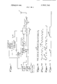
- FIG, I is a block diagram of the transmitter of this invention.
- FIG. 2 is a block diagram of the transmitter encoder.
- FIGS. 3A 3D illustrate wave shapes for explanatory purposes of the invention.
- FIG. 4 is a block diagram of the receiver of the invention.
- FIG. 5 is a block diagram of the receiver decoder.
- the present invention relates to a transmitter and receiver in which a serially transmitted digital code can be established in the transmitter by setting a number of two position switches so as to transmit on a radio frequency carrier a plurality of binary pulses representative of ones or zeroes as determined by the pulse length.
- a receiver within radio frequency range is provided with an equal number of two position switches which may be set to a particular binary code such that a receiver set to the particular code of the transmitter will recognize the code and energize the receiver thus actuating a garage door or other device.
- FIGS. 1 and 2 illustrate the transmitter of the invention.
- FIG. 1 illustrates an antenna 11 which receives a input from a radio frequency oscillator 10 from a lead 54 which is connected to the output of a one or zero decoder 12.
- a shift register 13 supplies an input to the decoder 12.
- a plurality of two position switches 14 are connected to the shift register to establish a binary code.
- a NOR gate 16 supplies an input to the shift register 13.
- An oscillator 17 which might oscillate at one kilohertz, for example, supplies an output to a divider 18 which divides the oscillator output by two.
- the divider 18 supplies an input to the decoder 12.
- a divider 19 receives the output from the divider 18 and divides it by two and supplies an output to the NOR gate 16.
- a divider 21 divides inputs by ten received from the dividers 18 and 19.
- a divider 22 receives the output of the divider 21 and divides it by two.
- Divider 22 supplies an input to the decoder 12 and supplies an input to the NOR gate 16 and to the shift register 13.
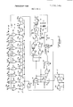
- FIG. 2 illustrates the transmitter encoder system in greater detail.
- the loading switches 14 are exemplified by nine, switches -1, which have two positions wherein either a positive voltage or ground potential may be selected by the switches 14.
- a plurality of NOR gates 38-46 are respectively connected to the switches 140-1 and also receive inputs from a Q-bar output of divider 22.
- An eleven-bit shift register is made up of integrated circuits 27-37 with the stages 27-35 respectively connected to the outputs of the NOR gates 38-46.
- a NOR gate 16 supplies inputs to the stages 27-37 and receives inputs from the divider l9 and the divider 22.
- the free-running oscillator 17 comprises the NOR gates 23 and 24 and are connected to the resistors R and R and the capacitor C.
- the output of NOR gate 24 is supplied to the divider 18.
- the output of the divider I8 is connected to the divider I9 and to NOR gates 26 and 49.
- the NOR gate 26 also receives an output from the divider 19.
- the divider 21 supplies an input to the divider 22.
- a NAND gate 47 receives inputs from the divider l8 and the divider 19 as well as from stage 37 of the shift register.
- a NAND gate 48 receives the output of the NAND gate 47 and supplies an output to a NOR gate 52.
- a NOR gate 51 receives an input from the NOR gate 49 and an input from the stage 37 and supplies an input to the NOR gate 52.
- a NOR gate 53 receives an output from a NOR gate 52 and the Q output from the divider 22.
- a capacitor C3 is connected between the 0 output of the divider 22 ground.
- a transistor T has its base connected to the output of the NOR gate 53 and its emitter is connected to lead 54 which is connected to key the RF oscillator 10. Its collector is connected to an on-off switch 55 which has its other side connected to the positive terminal of a battery E which has its other side grounded.
- a resistor R3 is connected to a Zener diode D1 and a capacitor C1 which have their opposite sides connected to ground.
- the switches l4a-l4z' are set to the particular code to which the receiver will be set.
- the freerunning oscillator 17 oscillates at one kilohertz which is divided by the dividers 18 and 19 to 500 and 250 hertz, respectively.
- the outputs of the dividers l8 and 19 are fed to the NOR gate 26 and into the divide by 10 divider 21 which supplies an input to the divide by two divider 22.
- the Q output of the divider 22 which is formed of an integrated circuit.
- the dead time will continue for 40ms during which time the dividers 21 and 22 will have counted another 20 pulses at which time the clock 17 output will be gated into the register and the NOR loading gates 38-46 will again be disabled.
- the ones and zeros in the register will then be clocked out every 4ms into the decoder section comprising the NAND gates 47 and 48 and the NOR gates 49, 51, 52, and 53.
- the NAND gates 47 and 48 will give a lms output for a one output from the register and the NOR gates 49 and 51 will give a 3ms output for a zero register output. These outputs are then ored together into the emitter follower TI which then keys the RF oscillator by lead 54.
- wave shape 57 is the output of the divider l8 and wave shape 58 is the out put of the divider 19.
- the output on lead 54 is illustrated in FIG. 3C comprising lms pulses representing ones and designated 61 in FIG. 3C and 3ms pulses designated by numeral 62 which represent zeroes.
- FIG. 3D illustrates the 40ms period 63 during which the pulses are supplied through the lead 54 to key the RF oscillator l0 and during which time they are radiated and the pulse 64 represents the dead time during which time the shift register is loaded.
- An antenna 6I receives the signal from the transmitter and supplies it to a radio frequency receiver 62 which supplies an output through a threshold circuit 63 to a -bit shift register 64.
- Incoming pulses from the output of the threshold circuit 63 triggers a one shot 66 which provides a Zms output to the data input of the shift register 64.
- the register 64 is clocked on the trailing edge of the input pulse and a one or item will be clocked into it depending on whether the 2ms data pulse is still present or not.
- the register fills up with the incoming data and parallel outputs from the shift register 64 are supplied to a code detector 67 which compares the received information in the shift register with the positions of the code selection switches 68 associated with a particular receiver. If the code in the shift register 64 is the same as the setting of the switches 68 an output is provided by the code detector 67 through a correct code counter 69 which supplies an output memory 71 if four correct codes are counted during four sequential inputs; and if so, an output is supplied on lead 133 to energize the load 72.
- An OR gate 74 receives an output from the code detector 67 and supplies an input to the shift register 64.
- a frame sync one shot 73 receives an output of the threshold circuit 63 and supplies an input to the OR gate 74.
- An AND gate 76 receives an input from the threshold circuit 63 and an input from a 0.5 second Retrig one shot 78.
- the AND gate 76 supplies an output to an OR gate 77 which also receives an input from a three pulse gobbler 79.
- the OR gate 77 supplies an input to the Retrig one shot 78.
- the Retrig one shot also supplies a reset input to the three pulse gobbler and also supplies reset inputs to the correct code counter 69 and the output memory 71.
- the three pulse gobbler also receives an input from the code detector.
- FIG. 5 is a detail block diagram of the logic constructure of the receiver decoder.
- the receiver decoder as illustrated in FIG. 5 consists of an input amplifier T2 which receives an input signal on terminal 81 through the condenser C7 from thresh old circuit 63 illustrated in FIG. 4 which in turn receives an input from the RF receiver 62 and the antenna 61.
- the output of the amplifier T2 is supplied through an exclusive OR gate 82 to the one shot 66 comprising the NOR gates 92, 93, 94, and 96.
- the output of the NOR gate 96 is supplied to integrated circuit 97 which with integrated circuits I18 and H9 form the shift register of the device.
- the output of the exclusive OR gate 82 is also supplied to the exclusive OR gate 83 which supplies incoming data to the shift registers 97, I I8, and 119.
- a plurality of comparator gates comprising exclusive OR gates 98, 99, I01, 103, I04, 107, 108, I09. and Ill and I13 and NAND gates I02, 106, and 112 receive inputs from the receiver code selector switches 680-681.
- a correct code counter comprises integrated circuits I21 and 122.
- An incoming pulse at terminal 81 triggers 2ms one shot 92, 93, 94, and 96 which drives the registers data input.
- the register is clocked on the trailing edge of the input pulse and a one or zero will be clocked into it depending upon whether the 2ms data pulse is still present or not.
- the register fills up and a one in the last position enables the compare function of integrated circuits 93, 94, 96, 98, 99, I01, 102, 103, I04, 106, 107, I08, 109, III, I I2, and H3.
- the present of this last bit causes the register to be reset to zero through the integrated circuit comprising the NOR gates 123, 124, 126, I27. and 128.
- An incoming pulse will set a 0.5 second one shot composed of NOR gates 84, 86, 87, 88, 89, and 91. This allows a one-half second interval for correct codes to be received or the counter and the register will be reset. However, a correct code occurring within this interval will retrigger the one shot holding the window open for more code reception.
- the last resetting function is provided by integrated circuit comprising the NOR gates 123, I24, I26, and 127.
- Incoming pulses supplied from the exclusive OR gate 82 fire its associated field effect transistor T5 holding capacitor C discharged. An absence of pulses for about ms will allow capacitor C10 to charge to a gate threshold resetting the register. This action reinitiates the register and provides needed sync between code frames.
- the integrated circuits 18 and 22 may be type MC 14501.
- the integrated circuit 21 may be type MC 14510.
- the D flops 27-37 may be MC 14013 and the NOR gates may be MC 14001.
- the exclusive OR devices 82, 83, 98, 99, 101, 103, 104, I07, 108, 109, 111, 113 may be integrated circuits MC 14507.
- the NOR gates 102, 106, and 112 may be integrated circuits MC 14025.
- the integrated circuits 97, 118, 119, 121, and 122 may be type MC 14015.
- the NAND gates 114 and 116 may be type MC 14012.
- the NOR gates 123, 124, 126, 127, 84, 86, 87, 88, 89, and 91, 129, 131, 132, and 117 may be type MC 14001.
- Transistor T2 may be type MPS 6571.
- Field effect transistors T3, T4, and T5 may be type 3N 170.
- the code selector switches 14 and 68 in the transmitter and receiver are set to the same binary combination, as for example, in the particular example the movable contacts 14c and Me and 14f are connected to ground and the corresponding code selector switches 68c, 68e and 68f in the receiver are connected to ground.
- the transmitter and receiver are, of course, at the same RF frequency.
- the transmitter is keyed on to transmit in sequence the binary code with the ones and zeroes having different time length pulses as illustrated in FIG. 3C.
- the receiver receives the transmitted pulses and supplies them through the transistor T1 through the one shot and to the 10 bit shift register wherein the incoming code is then compared with the setting of the switches 68a-i.
- the correct code counter 121 and 122 will receive an input from the NAND gate 116; and upon the reception of four sequences of code, output will be supplied to terminal 133 thus keying the load.
- the load may, for example, be a garage door actuator which can be opened or closed with the transmitter and receiver.
- Digital coding of radio controls in the invention is ac complished by transmitting a series of pulses called a pulse train in which each pulse can have one of two lengths dependent on the position of a single pole switch.
- the number of available codes depends on the number of switches. Since there are two distinct pulse widths the formula for the number of codes is 2" where n is the number of switches, for seven switches 2" is 128, eight switches 256, nine switches 512 etc.
- the system is capable of 128,256 or 512 digital codes multiplied by the number of RF channels, which for 11 channels and 512 digital codes would be 512 times 11 RF channels to obtain 5832 useable codes.
- the means of changing codes by the user requires no test equipment and needs to only set the switches in both receiver and transmitter. in the event a transmitter or receiver had to be replaced they would only need returning to the RF channel if different and the digital code could be quickly set and only one model receiver and transmitter would have to be stocked.
- the gates 98-114 comprise a comparison means for comparing the incoming data in the shift register integrated circuits 97, 118 and 119 with the setting of the switches 680-681.
- the exclusive OR gate 98 compares the input from switch 680 with the input in shift register 97 and supplies an input to NOR gate 102.
- NOR gate 102 also receives inputs from exclusive OR gates 99 and 104.
- These OR gates compare the positions of switches 68!: and 682 with the data in the shift registers 97 and 118.
- the data in the shift register is compared with the data set by the switches and if they are the same an output is supplied through gates 114 and 117 to the code counter comprising circuits 121 and 122.
- a coding system for a transmitter and receiver so that a selected receiver will respond to a particular transmitter comprising a transmitter capable of transmitting a RF signal in a binary code having pulses having time lengths T1 and T2 of different times, means at said transmitter for setting said binary code to a selected combination, a receiver tuned to said RF signal, and including code comparing means receiving the incoming binary code, means at said receiver for setting a binary code to a selected combination supplying an input to said code comparing means, output means are tuated by said comparing means if said means for setting a binary code at the transmtiter and receiver are set to the same code combination, wherein said means at said transmitter for setting said binary code includes a plurality of two position switches, a shift register connected to said plurality of two position switches, an oscillator to drive said shift register, divider means connected to said oscillator and to said shift register to reset it, a two pulse length generator connected to said shift register and to said dividers to produce said binary code and a RF oscill
- a coding system including means to cause said transmitter to transmit said binary code signal a number of times with a time interval between succeeding transmissions including a switch connected for keying said RF oscillator.
- a coding system according to claim 1 wherein said means at said receiver for setting a binary code comprises a plurality of two position switches.
- a code system including a threshold circuit connected to the input of said code comparing means and passing only signals which exceed a preset amplitude.
- said code comparing means comprises a shift register into which received incoming code signals are supplied and a plurality of gates receiving inputs from said shift register and said two position switches to produce an out put when said incoming code signals are the same as the code set by said two position switches.
- a coding system comprising means for resetting said shift register so as to receive incoming signals.
- a coding system including timing means connected to said correct code counter and memory circuit to reset it to zero at discrete time intervals.
Abstract
Description
Claims (8)
Priority Applications (4)
| Application Number | Priority Date | Filing Date | Title |
|---|---|---|---|
| US389806A US3906348A (en) | 1973-08-20 | 1973-08-20 | Digital radio control |
| CA196,247A CA1037125A (en) | 1973-08-20 | 1974-03-28 | Digital radio control |
| US05/718,311 USRE29525E (en) | 1973-08-20 | 1976-08-27 | Digital radio control |
| CA291,917A CA1037126A (en) | 1973-08-20 | 1977-11-29 | Digital radio control |
Applications Claiming Priority (1)
| Application Number | Priority Date | Filing Date | Title |
|---|---|---|---|
| US389806A US3906348A (en) | 1973-08-20 | 1973-08-20 | Digital radio control |
Related Child Applications (1)
| Application Number | Title | Priority Date | Filing Date |
|---|---|---|---|
| US05/718,311 Reissue USRE29525E (en) | 1973-08-20 | 1976-08-27 | Digital radio control |
Publications (1)
| Publication Number | Publication Date |
|---|---|
| US3906348A true US3906348A (en) | 1975-09-16 |
Family
ID=23539801
Family Applications (2)
| Application Number | Title | Priority Date | Filing Date |
|---|---|---|---|
| US389806A Expired - Lifetime US3906348A (en) | 1973-08-20 | 1973-08-20 | Digital radio control |
| US05/718,311 Expired - Lifetime USRE29525E (en) | 1973-08-20 | 1976-08-27 | Digital radio control |
Family Applications After (1)
| Application Number | Title | Priority Date | Filing Date |
|---|---|---|---|
| US05/718,311 Expired - Lifetime USRE29525E (en) | 1973-08-20 | 1976-08-27 | Digital radio control |
Country Status (2)
| Country | Link |
|---|---|
| US (2) | US3906348A (en) |
| CA (1) | CA1037125A (en) |
Cited By (70)
| Publication number | Priority date | Publication date | Assignee | Title |
|---|---|---|---|---|
| US4005428A (en) * | 1975-05-15 | 1977-01-25 | Sound Technology, Inc. | Secure remote control communication systems |
| US4016532A (en) * | 1975-11-05 | 1977-04-05 | Rose Levi L | Emergency traffic control system with security transmission coding |
| US4037201A (en) * | 1975-11-24 | 1977-07-19 | Chamberlain Manufacturing Corporation | Digital radio control |
| US4047107A (en) * | 1974-05-18 | 1977-09-06 | Ferranti Limited | Pulse width responsive security system |
| US4103238A (en) * | 1976-11-26 | 1978-07-25 | The Alliance Manufacturing Company | Transmitter modulated with three modulation patterns |
| US4134108A (en) * | 1977-01-21 | 1979-01-09 | Res'Q, Inc. | Emergency alarm device |
| US4141010A (en) * | 1976-04-07 | 1979-02-20 | Multi-Elmac Company | Digital encoder for door operator |
| EP0000986A1 (en) * | 1977-08-19 | 1979-03-07 | BIOTRONIK Mess- und Therapiegeräte GmbH & Co Ingenieurbüro Berlin | Programmer for implanted pacer |
| EP0001156A1 (en) * | 1977-08-19 | 1979-03-21 | BIOTRONIK Mess- und Therapiegeräte GmbH & Co Ingenieurbüro Berlin | Programmable, implantable body function control apparatus and method for reprogramming said apparatus |
| FR2412127A1 (en) * | 1977-12-15 | 1979-07-13 | Berutto & C Alarm Snc | Remote control using pulse signals - has alternate signal and sync. pulses, and error control to enable use of max. number of channels |
| US4178549A (en) * | 1978-03-27 | 1979-12-11 | National Semiconductor Corporation | Recognition of a received signal as being from a particular transmitter |
| US4203447A (en) * | 1977-08-19 | 1980-05-20 | Biotronik Mess- Und Therapiegerate Gmbh & Co. | Security maintenance for programmable pacer reprogramming |
| US4207524A (en) * | 1977-12-23 | 1980-06-10 | Purchase Francis J | Radio coupled device for detecting and analyzing weak transmissions |
| EP0011947A2 (en) * | 1978-11-06 | 1980-06-11 | Medtronic, Inc. | Programmable medical device |
| US4231031A (en) * | 1977-02-09 | 1980-10-28 | U.S. Philips Corporation | Remote control system capable of transmitting the information with the aid of an infra red beam using PPM or an ultrasonic beam using PDM |
| DE3015072A1 (en) * | 1979-04-19 | 1980-10-30 | Hitachi Ltd | GARAGE DOOR OPERATING CONTROL DEVICE |
| DE3016337A1 (en) * | 1979-04-30 | 1980-11-13 | Gould Inc | LOW TIRE WARNING SYSTEM |
| DE3016338A1 (en) * | 1979-04-30 | 1980-11-13 | Gould Inc | DIGITAL CODED DISPLAY SYSTEM FOR ABNORMAL TIRE CONDITIONS |
| US4247850A (en) * | 1977-08-05 | 1981-01-27 | Prince Corporation | Visor and garage door operator assembly |
| US4258352A (en) * | 1978-03-17 | 1981-03-24 | Neiman, S.A. | Control device for vehicle locks |
| DE3012465A1 (en) * | 1980-03-31 | 1981-10-08 | Hitachi, Ltd., Tokyo | Automatic garage door operating mechanism - has door holding end switches incorporated in drive unit and released upon disconnection of drive |
| US4314371A (en) * | 1979-08-17 | 1982-02-02 | Covington Edward L | Digital radio communications system with high noise immunity |
| US4328540A (en) * | 1979-02-23 | 1982-05-04 | Hitachi, Ltd. | Door operation control apparatus |
| US4385296A (en) * | 1978-06-14 | 1983-05-24 | Hitachi, Ltd. | Remote-controlled automatic control apparatus |
| US4396910A (en) * | 1980-05-02 | 1983-08-02 | American District Telegraph Company | Coded security switch |
| JPS6037380A (en) * | 1983-08-08 | 1985-02-26 | トヨタ自動車株式会社 | Keyless entry apparatus |
| US4590471A (en) * | 1983-12-28 | 1986-05-20 | The United States Of America As Represented By The Secretary Of The Air Force | Electroluminescent (EL) remotely-controlled landing zone marker light system |
| US4686707A (en) * | 1984-05-29 | 1987-08-11 | Pioneer Electronic Corporation | Program identifier signal receiver |
| US4712104A (en) * | 1985-04-19 | 1987-12-08 | Kuron Kabushiki Kaisha | Remote control blind system |
| WO1988006385A1 (en) * | 1987-02-23 | 1988-08-25 | Zeeng, Pauline | Transmission and reception of data |
| US4779265A (en) * | 1986-10-27 | 1988-10-18 | Bell Communications Research, Inc. | Multiple access communication system |
| US4779266A (en) * | 1986-03-10 | 1988-10-18 | Bell Communications Research, Inc. | Encoding and decoding for code division multiple access communication systems |
| US4780621A (en) * | 1987-06-30 | 1988-10-25 | Frank J. Bartleucci | Ornamental lighting system |
| US4808995A (en) * | 1986-05-02 | 1989-02-28 | Stanley Automatic Openers | Accessory-expandable, radio-controlled, door operator with multiple security levels |
| US4835533A (en) * | 1985-10-28 | 1989-05-30 | Kokusan Kinzoku Kogyo Kabushiki Kaisha | Vehicle-use locking and unlocking system |
| US4857921A (en) * | 1986-05-30 | 1989-08-15 | Flagman, Inc. | Digital traffic control system |
| DE4016207A1 (en) * | 1990-05-19 | 1991-11-21 | Werner Seider | Vehicle tyre air pressure measurement arrangement - contains measurement piston in non-magnetic measurement tube with e.g. inductive sensor |
| DE4123640A1 (en) * | 1991-07-17 | 1993-01-21 | Huegle Pfullendorf Kipptor | Remote control for automatic garage door - uses car radio antenna to transmit remote control signals to door operating drive |
| US5386713A (en) * | 1991-03-07 | 1995-02-07 | Wilson; Bert | Remote control car deadbolt lock |
| WO1996037063A1 (en) * | 1995-05-17 | 1996-11-21 | The Chamberlain Group, Inc. | Rolling code security system |
| US5685507A (en) * | 1994-04-01 | 1997-11-11 | Canac International Incorporated | Remote control system for a locomotive |
| US5751224A (en) * | 1995-05-17 | 1998-05-12 | The Chamberlain Group, Inc. | Code learning system for a movable barrier operator |
| US5872513A (en) * | 1996-04-24 | 1999-02-16 | The Chamberlain Group, Inc. | Garage door opener and wireless keypad transmitter with temporary password feature |
| US5949349A (en) * | 1997-02-19 | 1999-09-07 | The Chamberlain Group, Inc. | Code responsive radio receiver capable of operation with plural types of code transmitters |
| US6025785A (en) * | 1996-04-24 | 2000-02-15 | The Chamberlain Group, Inc. | Multiple code formats in a single garage door opener including at least one fixed code format and at least one rolling code format |
| US6035002A (en) * | 1995-06-05 | 2000-03-07 | The Chamberlain Group, Inc. | Digital super-regenerative detector RF receiver |
| US6049289A (en) * | 1996-09-06 | 2000-04-11 | Overhead Door Corporation | Remote controlled garage door opening system |
| USRE36703E (en) * | 1984-05-30 | 2000-05-16 | The Chamberlain Group, Inc. | Coding system for multiple transmitters and a single receiver for a garage door opener |
| US6118828A (en) * | 1995-06-05 | 2000-09-12 | The Chamberlain Group, Inc. | Digital super-regenerative detector RF receiver |
| US6137405A (en) * | 1999-08-12 | 2000-10-24 | Carney; William P. | Remotely controlled intrusion alarm and detection system |
| US6175312B1 (en) | 1990-05-29 | 2001-01-16 | Microchip Technology Incorporated | Encoder and decoder microchips and remote control devices for secure unidirectional communication |
| US6369708B2 (en) * | 1999-08-12 | 2002-04-09 | William P. Carney | Intrusion alarm and detection system |
| US6414587B1 (en) | 1998-03-13 | 2002-07-02 | The Chamberlain Group, Inc. | Code learning system for a movable barrier operator |
| US6486795B1 (en) * | 1998-07-31 | 2002-11-26 | The Chamberlain Group, Inc. | Universal transmitter |
| US6661350B1 (en) | 1999-09-24 | 2003-12-09 | Creative Commands Corporation | Miniature remote control system |
| US6690796B1 (en) | 1995-05-17 | 2004-02-10 | The Chamberlain Group, Inc. | Rolling code security system |
| US6810123B2 (en) | 1995-05-17 | 2004-10-26 | The Chamberlain Group, Inc. | Rolling code security system |
| US6995682B1 (en) * | 2000-10-30 | 2006-02-07 | Ramsey Winch Company | Wireless remote control for a winch |
| US7071850B1 (en) * | 2005-01-27 | 2006-07-04 | The Chamberlain Group, Inc. | Method and apparatus to facilitate transmission of ternary movable barrier operator information |
| US20060186844A1 (en) * | 1998-09-28 | 2006-08-24 | The Chamberlain Group, Inc. | Movable barrier operator |
| US20070005806A1 (en) * | 2005-06-30 | 2007-01-04 | The Chamberlain Group, Inc. | Method and apparatus to facilitate message transmission and reception using defferent transmission characteristics |
| US7492905B2 (en) | 1995-05-17 | 2009-02-17 | The Chamberlain Group, Inc. | Rolling code security system |
| US8325008B2 (en) | 2001-04-25 | 2012-12-04 | The Chamberlain Group, Inc. | Simplified method and apparatus for programming a universal transmitter |
| US8422667B2 (en) | 2005-01-27 | 2013-04-16 | The Chamberlain Group, Inc. | Method and apparatus to facilitate transmission of an encrypted rolling code |
| US9357376B2 (en) | 2013-07-31 | 2016-05-31 | Ip.Access Limited | Network elements, wireless communication system and methods therefor |
| WO2019126453A1 (en) | 2017-12-21 | 2019-06-27 | The Chamberlain Group, Inc. | Security system for a moveable barrier operator |
| USRE48433E1 (en) | 2005-01-27 | 2021-02-09 | The Chamberlain Group, Inc. | Method and apparatus to facilitate transmission of an encrypted rolling code |
| US10997810B2 (en) | 2019-05-16 | 2021-05-04 | The Chamberlain Group, Inc. | In-vehicle transmitter training |
| US11074773B1 (en) | 2018-06-27 | 2021-07-27 | The Chamberlain Group, Inc. | Network-based control of movable barrier operators for autonomous vehicles |
| US11423717B2 (en) | 2018-08-01 | 2022-08-23 | The Chamberlain Group Llc | Movable barrier operator and transmitter pairing over a network |
Families Citing this family (33)
| Publication number | Priority date | Publication date | Assignee | Title |
|---|---|---|---|---|
| US4169286A (en) * | 1978-06-09 | 1979-09-25 | Communications Satellite Corporation | Surface acoustic wave unique word detector and coherent demodulator |
| US4750118A (en) | 1985-10-29 | 1988-06-07 | Chamberlain Manufacturing Corporation | Coding system for multiple transmitters and a single receiver for a garage door opener |
| US4638433A (en) | 1984-05-30 | 1987-01-20 | Chamberlain Manufacturing Corporation | Microprocessor controlled garage door operator |
| US4881148A (en) | 1987-05-21 | 1989-11-14 | Wickes Manufacturing Company | Remote control system for door locks |
| US5252966A (en) * | 1987-05-21 | 1993-10-12 | Trw Inc. | Transmitter for remote control system for door locks |
| US5109221A (en) * | 1987-05-21 | 1992-04-28 | Trw Inc. | Remote control system for door locks |
| US5479155A (en) * | 1988-12-05 | 1995-12-26 | Prince Corporation | Vehicle accessory trainable transmitter |
| US5614885A (en) | 1988-12-05 | 1997-03-25 | Prince Corporation | Electrical control system for vehicle options |
| US5442340A (en) * | 1988-12-05 | 1995-08-15 | Prince Corporation | Trainable RF transmitter including attenuation control |
| US5475366A (en) * | 1988-12-05 | 1995-12-12 | Prince Corporation | Electrical control system for vehicle options |
| US4988992A (en) * | 1989-07-27 | 1991-01-29 | The Chamberlain Group, Inc. | System for establishing a code and controlling operation of equipment |
| US5627529A (en) * | 1994-03-11 | 1997-05-06 | Prince Corporation | Vehicle control system with trainable transceiver |
| US5686904A (en) * | 1991-05-29 | 1997-11-11 | Microchip Technology Incorporated | Secure self learning system |
| US5223818A (en) * | 1992-02-10 | 1993-06-29 | Polo Benito L | Concealed remote alarm activator |
| US5903226A (en) * | 1993-03-15 | 1999-05-11 | Prince Corporation | Trainable RF system for remotely controlling household appliances |
| DE69533637T2 (en) | 1994-06-21 | 2006-02-16 | Microchip Technology Inc., Chandler | Protected self-learning |
| US5841866A (en) * | 1994-09-30 | 1998-11-24 | Microchip Technology Incorporated | Secure token integrated circuit and method of performing a secure authentication function or transaction |
| US5699054A (en) * | 1995-05-19 | 1997-12-16 | Prince Corporation | Trainable transceiver including a dynamically tunable antenna |
| US5686903A (en) * | 1995-05-19 | 1997-11-11 | Prince Corporation | Trainable RF transceiver |
| US5699055A (en) * | 1995-05-19 | 1997-12-16 | Prince Corporation | Trainable transceiver and method for learning an activation signal that remotely actuates a device |
| US5661804A (en) * | 1995-06-27 | 1997-08-26 | Prince Corporation | Trainable transceiver capable of learning variable codes |
| US6191701B1 (en) | 1995-08-25 | 2001-02-20 | Microchip Technology Incorporated | Secure self learning system |
| US5699065A (en) * | 1996-01-16 | 1997-12-16 | Stanley Home Automation | Remote control transmitter and method of operation |
| US6108326A (en) * | 1997-05-08 | 2000-08-22 | Microchip Technology Incorporated | Microchips and remote control devices comprising same |
| US7642895B2 (en) * | 1999-12-20 | 2010-01-05 | The Chamberlain Group, Inc. | Garage door operator having thumbprint identification system |
| US6338664B1 (en) | 2000-06-12 | 2002-01-15 | New Bright Industrial Co., Ltd. | Toy vehicle having center steering circuit and remote controller with toggle function |
| WO2002050782A2 (en) * | 2000-12-19 | 2002-06-27 | Azoteq (Pty) Ltd | Method of and apparatus for transferring data |
| US6726192B2 (en) * | 2001-12-13 | 2004-04-27 | Lawrence N. Devers | Wood panel clamping tool |
| US7107040B2 (en) | 2002-02-11 | 2006-09-12 | The Chamberlain Group, Inc. | Method and apparatus for displaying blocked transmitter information |
| US6756895B2 (en) | 2002-02-11 | 2004-06-29 | The Chamberlain Group, Inc. | Device learning mode method |
| US6832076B2 (en) | 2002-02-11 | 2004-12-14 | The Chamberlain Group, Inc. | Audible diagnostic information apparatus and method |
| US6990317B2 (en) * | 2002-05-28 | 2006-01-24 | Wireless Innovation | Interference resistant wireless sensor and control system |
| US7439747B2 (en) * | 2006-12-27 | 2008-10-21 | Beeman Terrence M | Location of high resistance ground faults on buried power-cables |
Citations (7)
| Publication number | Priority date | Publication date | Assignee | Title |
|---|---|---|---|---|
| US2812509A (en) * | 1953-08-31 | 1957-11-05 | Sperry Rand Corp | Private line system |
| US2996704A (en) * | 1956-01-19 | 1961-08-15 | Bell Telephone Labor Inc | Method of and apparatus for generating coded signals |
| US3261920A (en) * | 1961-12-01 | 1966-07-19 | Bell Telephone Labor Inc | Asynchronous pulse multiplexing |
| US3510780A (en) * | 1966-09-12 | 1970-05-05 | Motorola Inc | Two-state communication devices having combined clock and information signals |
| US3510777A (en) * | 1967-05-10 | 1970-05-05 | Corn Products Co | Digital stream selective calling system |
| US3596181A (en) * | 1966-03-04 | 1971-07-27 | Amp Inc | Selective signalling system |
| US3716836A (en) * | 1970-05-22 | 1973-02-13 | Thomson Csf | Data code conversion for remote signalling and control systems |
Family Cites Families (4)
| Publication number | Priority date | Publication date | Assignee | Title |
|---|---|---|---|---|
| US3175191A (en) * | 1960-01-14 | 1965-03-23 | Motorola Inc | Binary code signalling system having a binary counter at the receiver responsive to a selected code |
| US3378817A (en) * | 1964-12-09 | 1968-04-16 | Gen Electric | Signalling systems |
| US3384873A (en) * | 1965-01-22 | 1968-05-21 | Collins Radio Co | Selective calling system |
| US3649756A (en) * | 1970-12-16 | 1972-03-14 | Computer Transceiver Systems | Generator of binary-coded representations of symbols |
-
1973
- 1973-08-20 US US389806A patent/US3906348A/en not_active Expired - Lifetime
-
1974
- 1974-03-28 CA CA196,247A patent/CA1037125A/en not_active Expired
-
1976
- 1976-08-27 US US05/718,311 patent/USRE29525E/en not_active Expired - Lifetime
Patent Citations (7)
| Publication number | Priority date | Publication date | Assignee | Title |
|---|---|---|---|---|
| US2812509A (en) * | 1953-08-31 | 1957-11-05 | Sperry Rand Corp | Private line system |
| US2996704A (en) * | 1956-01-19 | 1961-08-15 | Bell Telephone Labor Inc | Method of and apparatus for generating coded signals |
| US3261920A (en) * | 1961-12-01 | 1966-07-19 | Bell Telephone Labor Inc | Asynchronous pulse multiplexing |
| US3596181A (en) * | 1966-03-04 | 1971-07-27 | Amp Inc | Selective signalling system |
| US3510780A (en) * | 1966-09-12 | 1970-05-05 | Motorola Inc | Two-state communication devices having combined clock and information signals |
| US3510777A (en) * | 1967-05-10 | 1970-05-05 | Corn Products Co | Digital stream selective calling system |
| US3716836A (en) * | 1970-05-22 | 1973-02-13 | Thomson Csf | Data code conversion for remote signalling and control systems |
Cited By (105)
| Publication number | Priority date | Publication date | Assignee | Title |
|---|---|---|---|---|
| US4047107A (en) * | 1974-05-18 | 1977-09-06 | Ferranti Limited | Pulse width responsive security system |
| US4005428A (en) * | 1975-05-15 | 1977-01-25 | Sound Technology, Inc. | Secure remote control communication systems |
| US4016532A (en) * | 1975-11-05 | 1977-04-05 | Rose Levi L | Emergency traffic control system with security transmission coding |
| US4037201A (en) * | 1975-11-24 | 1977-07-19 | Chamberlain Manufacturing Corporation | Digital radio control |
| US4141010A (en) * | 1976-04-07 | 1979-02-20 | Multi-Elmac Company | Digital encoder for door operator |
| US4103238A (en) * | 1976-11-26 | 1978-07-25 | The Alliance Manufacturing Company | Transmitter modulated with three modulation patterns |
| US4134108A (en) * | 1977-01-21 | 1979-01-09 | Res'Q, Inc. | Emergency alarm device |
| US4231031A (en) * | 1977-02-09 | 1980-10-28 | U.S. Philips Corporation | Remote control system capable of transmitting the information with the aid of an infra red beam using PPM or an ultrasonic beam using PDM |
| US4247850A (en) * | 1977-08-05 | 1981-01-27 | Prince Corporation | Visor and garage door operator assembly |
| EP0001156A1 (en) * | 1977-08-19 | 1979-03-21 | BIOTRONIK Mess- und Therapiegeräte GmbH & Co Ingenieurbüro Berlin | Programmable, implantable body function control apparatus and method for reprogramming said apparatus |
| US4203447A (en) * | 1977-08-19 | 1980-05-20 | Biotronik Mess- Und Therapiegerate Gmbh & Co. | Security maintenance for programmable pacer reprogramming |
| EP0000986A1 (en) * | 1977-08-19 | 1979-03-07 | BIOTRONIK Mess- und Therapiegeräte GmbH & Co Ingenieurbüro Berlin | Programmer for implanted pacer |
| FR2412127A1 (en) * | 1977-12-15 | 1979-07-13 | Berutto & C Alarm Snc | Remote control using pulse signals - has alternate signal and sync. pulses, and error control to enable use of max. number of channels |
| US4207524A (en) * | 1977-12-23 | 1980-06-10 | Purchase Francis J | Radio coupled device for detecting and analyzing weak transmissions |
| US4258352A (en) * | 1978-03-17 | 1981-03-24 | Neiman, S.A. | Control device for vehicle locks |
| US4178549A (en) * | 1978-03-27 | 1979-12-11 | National Semiconductor Corporation | Recognition of a received signal as being from a particular transmitter |
| US4385296A (en) * | 1978-06-14 | 1983-05-24 | Hitachi, Ltd. | Remote-controlled automatic control apparatus |
| EP0011947A3 (en) * | 1978-11-06 | 1981-01-07 | Medtronic, Inc. | Programmable medical device |
| EP0011947A2 (en) * | 1978-11-06 | 1980-06-11 | Medtronic, Inc. | Programmable medical device |
| US4328540A (en) * | 1979-02-23 | 1982-05-04 | Hitachi, Ltd. | Door operation control apparatus |
| DE3015072A1 (en) * | 1979-04-19 | 1980-10-30 | Hitachi Ltd | GARAGE DOOR OPERATING CONTROL DEVICE |
| DE3016338A1 (en) * | 1979-04-30 | 1980-11-13 | Gould Inc | DIGITAL CODED DISPLAY SYSTEM FOR ABNORMAL TIRE CONDITIONS |
| DE3016337A1 (en) * | 1979-04-30 | 1980-11-13 | Gould Inc | LOW TIRE WARNING SYSTEM |
| US4314371A (en) * | 1979-08-17 | 1982-02-02 | Covington Edward L | Digital radio communications system with high noise immunity |
| DE3012465A1 (en) * | 1980-03-31 | 1981-10-08 | Hitachi, Ltd., Tokyo | Automatic garage door operating mechanism - has door holding end switches incorporated in drive unit and released upon disconnection of drive |
| US4396910A (en) * | 1980-05-02 | 1983-08-02 | American District Telegraph Company | Coded security switch |
| JPS6037380A (en) * | 1983-08-08 | 1985-02-26 | トヨタ自動車株式会社 | Keyless entry apparatus |
| JPH0584351B2 (en) * | 1983-08-08 | 1993-12-01 | Toyota Motor Co Ltd | |
| US4590471A (en) * | 1983-12-28 | 1986-05-20 | The United States Of America As Represented By The Secretary Of The Air Force | Electroluminescent (EL) remotely-controlled landing zone marker light system |
| US4686707A (en) * | 1984-05-29 | 1987-08-11 | Pioneer Electronic Corporation | Program identifier signal receiver |
| USRE37986E1 (en) | 1984-05-30 | 2003-02-11 | The Chamberlain Group, Inc. | Coding system for multiple transmitters and a single receiver |
| USRE36703E (en) * | 1984-05-30 | 2000-05-16 | The Chamberlain Group, Inc. | Coding system for multiple transmitters and a single receiver for a garage door opener |
| US4712104A (en) * | 1985-04-19 | 1987-12-08 | Kuron Kabushiki Kaisha | Remote control blind system |
| US4835533A (en) * | 1985-10-28 | 1989-05-30 | Kokusan Kinzoku Kogyo Kabushiki Kaisha | Vehicle-use locking and unlocking system |
| US4779266A (en) * | 1986-03-10 | 1988-10-18 | Bell Communications Research, Inc. | Encoding and decoding for code division multiple access communication systems |
| US4808995A (en) * | 1986-05-02 | 1989-02-28 | Stanley Automatic Openers | Accessory-expandable, radio-controlled, door operator with multiple security levels |
| US4857921A (en) * | 1986-05-30 | 1989-08-15 | Flagman, Inc. | Digital traffic control system |
| US4779265A (en) * | 1986-10-27 | 1988-10-18 | Bell Communications Research, Inc. | Multiple access communication system |
| WO1988006385A1 (en) * | 1987-02-23 | 1988-08-25 | Zeeng, Pauline | Transmission and reception of data |
| US4780621A (en) * | 1987-06-30 | 1988-10-25 | Frank J. Bartleucci | Ornamental lighting system |
| DE4016207A1 (en) * | 1990-05-19 | 1991-11-21 | Werner Seider | Vehicle tyre air pressure measurement arrangement - contains measurement piston in non-magnetic measurement tube with e.g. inductive sensor |
| US6175312B1 (en) | 1990-05-29 | 2001-01-16 | Microchip Technology Incorporated | Encoder and decoder microchips and remote control devices for secure unidirectional communication |
| US5386713A (en) * | 1991-03-07 | 1995-02-07 | Wilson; Bert | Remote control car deadbolt lock |
| DE4123640A1 (en) * | 1991-07-17 | 1993-01-21 | Huegle Pfullendorf Kipptor | Remote control for automatic garage door - uses car radio antenna to transmit remote control signals to door operating drive |
| USRE39758E1 (en) | 1994-03-31 | 2007-08-07 | Cattron Intellectual Property Corporation | Remote control system for a locomotive |
| USRE39210E1 (en) * | 1994-03-31 | 2006-08-01 | Cattron Intellectual Property Corporation | Remote control system for a locomotive |
| USRE39011E1 (en) | 1994-03-31 | 2006-03-14 | Cattron Intellectual Property Corporation | Remote control system for a locomotive |
| US5685507A (en) * | 1994-04-01 | 1997-11-11 | Canac International Incorporated | Remote control system for a locomotive |
| US7492898B2 (en) | 1995-05-17 | 2009-02-17 | The Chamberlain Group, Inc. | Rolling code security system |
| US8194856B2 (en) | 1995-05-17 | 2012-06-05 | The Chamberlain Group, Inc. | Rolling code security system |
| US6081203A (en) * | 1995-05-17 | 2000-06-27 | Chamberlain Group, Inc. | Code learning system for a movable barrier operator |
| US5751224A (en) * | 1995-05-17 | 1998-05-12 | The Chamberlain Group, Inc. | Code learning system for a movable barrier operator |
| US8633797B2 (en) | 1995-05-17 | 2014-01-21 | The Chamberlain Group, Inc. | Rolling code security system |
| US6154544A (en) * | 1995-05-17 | 2000-11-28 | The Chamberlain Group, Inc. | Rolling code security system |
| US7412056B2 (en) | 1995-05-17 | 2008-08-12 | The Chamberlain Group, Inc. | Rolling code security system |
| US8284021B2 (en) | 1995-05-17 | 2012-10-09 | The Chamberlain Group, Inc. | Rolling code security system |
| US8233625B2 (en) | 1995-05-17 | 2012-07-31 | The Chamberlain Group, Inc. | Rolling code security system |
| US20080297370A1 (en) * | 1995-05-17 | 2008-12-04 | The Chamberlain Group, Inc. | Rolling code security system |
| US20090021348A1 (en) * | 1995-05-17 | 2009-01-22 | The Chamberlain Group, Inc. | Rolling code security system |
| US7623663B2 (en) | 1995-05-17 | 2009-11-24 | The Chamberlain Group, Inc. | Rolling code security system |
| US7492905B2 (en) | 1995-05-17 | 2009-02-17 | The Chamberlain Group, Inc. | Rolling code security system |
| US6690796B1 (en) | 1995-05-17 | 2004-02-10 | The Chamberlain Group, Inc. | Rolling code security system |
| WO1996037063A1 (en) * | 1995-05-17 | 1996-11-21 | The Chamberlain Group, Inc. | Rolling code security system |
| US6810123B2 (en) | 1995-05-17 | 2004-10-26 | The Chamberlain Group, Inc. | Rolling code security system |
| US6035002A (en) * | 1995-06-05 | 2000-03-07 | The Chamberlain Group, Inc. | Digital super-regenerative detector RF receiver |
| US6118828A (en) * | 1995-06-05 | 2000-09-12 | The Chamberlain Group, Inc. | Digital super-regenerative detector RF receiver |
| US6025785A (en) * | 1996-04-24 | 2000-02-15 | The Chamberlain Group, Inc. | Multiple code formats in a single garage door opener including at least one fixed code format and at least one rolling code format |
| US5872513A (en) * | 1996-04-24 | 1999-02-16 | The Chamberlain Group, Inc. | Garage door opener and wireless keypad transmitter with temporary password feature |
| US20040085185A1 (en) * | 1996-09-06 | 2004-05-06 | Overhead Door Corporation | Remote controlled garage door opening system |
| US6049289A (en) * | 1996-09-06 | 2000-04-11 | Overhead Door Corporation | Remote controlled garage door opening system |
| US6667684B1 (en) | 1996-09-06 | 2003-12-23 | Overhead Door Corporation | Remote controlled garage door opening system |
| US5949349A (en) * | 1997-02-19 | 1999-09-07 | The Chamberlain Group, Inc. | Code responsive radio receiver capable of operation with plural types of code transmitters |
| US6414587B1 (en) | 1998-03-13 | 2002-07-02 | The Chamberlain Group, Inc. | Code learning system for a movable barrier operator |
| US6486795B1 (en) * | 1998-07-31 | 2002-11-26 | The Chamberlain Group, Inc. | Universal transmitter |
| US20060186844A1 (en) * | 1998-09-28 | 2006-08-24 | The Chamberlain Group, Inc. | Movable barrier operator |
| US7164246B2 (en) * | 1998-09-28 | 2007-01-16 | The Chamberlain Group, Inc. | Movable barrier operator |
| US6137405A (en) * | 1999-08-12 | 2000-10-24 | Carney; William P. | Remotely controlled intrusion alarm and detection system |
| US6369708B2 (en) * | 1999-08-12 | 2002-04-09 | William P. Carney | Intrusion alarm and detection system |
| US6661350B1 (en) | 1999-09-24 | 2003-12-09 | Creative Commands Corporation | Miniature remote control system |
| US6980655B2 (en) | 2000-01-21 | 2005-12-27 | The Chamberlain Group, Inc. | Rolling code security system |
| US6995682B1 (en) * | 2000-10-30 | 2006-02-07 | Ramsey Winch Company | Wireless remote control for a winch |
| US8610547B2 (en) | 2001-04-25 | 2013-12-17 | The Chamberlain Group, Inc. | Simplified method and apparatus for programming a universal transmitter |
| US8325008B2 (en) | 2001-04-25 | 2012-12-04 | The Chamberlain Group, Inc. | Simplified method and apparatus for programming a universal transmitter |
| US11799648B2 (en) | 2005-01-27 | 2023-10-24 | The Chamberlain Group Llc | Method and apparatus to facilitate transmission of an encrypted rolling code |
| US20070018861A1 (en) * | 2005-01-27 | 2007-01-25 | The Chamberlain Group, Inc. | Method and apparatus to facilitate transmission of ternary movable barrier operator information |
| US7071850B1 (en) * | 2005-01-27 | 2006-07-04 | The Chamberlain Group, Inc. | Method and apparatus to facilitate transmission of ternary movable barrier operator information |
| US8422667B2 (en) | 2005-01-27 | 2013-04-16 | The Chamberlain Group, Inc. | Method and apparatus to facilitate transmission of an encrypted rolling code |
| US20060164267A1 (en) * | 2005-01-27 | 2006-07-27 | Fitzgibbon James J | Method and apparatus to facilitate transmission of ternary movable barrier operator information |
| US10944559B2 (en) | 2005-01-27 | 2021-03-09 | The Chamberlain Group, Inc. | Transmission of data including conversion of ternary data to binary data |
| US7561075B2 (en) | 2005-01-27 | 2009-07-14 | The Chamberlain Group, Inc. | Method and apparatus to facilitate transmission of ternary movable barrier operator information |
| USRE48433E1 (en) | 2005-01-27 | 2021-02-09 | The Chamberlain Group, Inc. | Method and apparatus to facilitate transmission of an encrypted rolling code |
| US20070005806A1 (en) * | 2005-06-30 | 2007-01-04 | The Chamberlain Group, Inc. | Method and apparatus to facilitate message transmission and reception using defferent transmission characteristics |
| US9148409B2 (en) | 2005-06-30 | 2015-09-29 | The Chamberlain Group, Inc. | Method and apparatus to facilitate message transmission and reception using different transmission characteristics |
| US10862924B2 (en) | 2005-06-30 | 2020-12-08 | The Chamberlain Group, Inc. | Method and apparatus to facilitate message transmission and reception using different transmission characteristics |
| US9357376B2 (en) | 2013-07-31 | 2016-05-31 | Ip.Access Limited | Network elements, wireless communication system and methods therefor |
| US10652743B2 (en) | 2017-12-21 | 2020-05-12 | The Chamberlain Group, Inc. | Security system for a moveable barrier operator |
| US11122430B2 (en) | 2017-12-21 | 2021-09-14 | The Chamberlain Group, Inc. | Security system for a moveable barrier operator |
| US11778464B2 (en) | 2017-12-21 | 2023-10-03 | The Chamberlain Group Llc | Security system for a moveable barrier operator |
| WO2019126453A1 (en) | 2017-12-21 | 2019-06-27 | The Chamberlain Group, Inc. | Security system for a moveable barrier operator |
| US11074773B1 (en) | 2018-06-27 | 2021-07-27 | The Chamberlain Group, Inc. | Network-based control of movable barrier operators for autonomous vehicles |
| US11763616B1 (en) | 2018-06-27 | 2023-09-19 | The Chamberlain Group Llc | Network-based control of movable barrier operators for autonomous vehicles |
| US11423717B2 (en) | 2018-08-01 | 2022-08-23 | The Chamberlain Group Llc | Movable barrier operator and transmitter pairing over a network |
| US11869289B2 (en) | 2018-08-01 | 2024-01-09 | The Chamberlain Group Llc | Movable barrier operator and transmitter pairing over a network |
| US10997810B2 (en) | 2019-05-16 | 2021-05-04 | The Chamberlain Group, Inc. | In-vehicle transmitter training |
| US11462067B2 (en) | 2019-05-16 | 2022-10-04 | The Chamberlain Group Llc | In-vehicle transmitter training |
Also Published As
| Publication number | Publication date |
|---|---|
| CA1037125A (en) | 1978-08-22 |
| USRE29525E (en) | 1978-01-24 |
Similar Documents
| Publication | Publication Date | Title |
|---|---|---|
| US3906348A (en) | Digital radio control | |
| US4141010A (en) | Digital encoder for door operator | |
| US3445815A (en) | Central to remote station signalling system | |
| US4412218A (en) | Remote control signal transmitter capable of setting custom codes individually alloted to a plurality of controlled instruments | |
| US4079414A (en) | Interrogated transponder system | |
| US4037201A (en) | Digital radio control | |
| US3803491A (en) | Communications system | |
| US5841364A (en) | Method and apparatus for transfering information from a transponder | |
| US3044065A (en) | Electronic programming means for synchronizing a plurality of remotely located similar means | |
| US3855575A (en) | Ultrasonic remote control receiver | |
| US3944742A (en) | Burst frequency shift keying data communication system | |
| US5450086A (en) | Self-tuning receiver/decoder for frequency shift keying RF data transmission | |
| US3949297A (en) | Information signal transmitting system | |
| GB1147028A (en) | Data communication system employing an asynchronous start stop clock generator | |
| US5155469A (en) | Wireless alarm system | |
| US3878322A (en) | Interrogated system | |
| US4091272A (en) | Infra-red remote controlled command system for a communications receiver | |
| US3692964A (en) | Remote-testing arrangement for two-way transmission channel of pcm telecommunication system | |
| US3541257A (en) | Communication response unit | |
| CA1120576A (en) | Digital remote control system with improved noise immunity | |
| US4251801A (en) | Mobile data communication system | |
| US3747108A (en) | Remote control system | |
| CA1092242A (en) | Method and apparatus for digital data transmission in television receiver remote control systems | |
| US3973241A (en) | Information transmission system | |
| US4006462A (en) | Digital remote control system with signal verification |
Legal Events
| Date | Code | Title | Description |
|---|---|---|---|
| STCF | Information on status: patent grant |
Free format text: PATENTED FILE - (OLD CASE ADDED FOR FILE TRACKING PURPOSES) |
|
| AS | Assignment |
Owner name: CHAMBERLAIN GROUP, THE, INC., 845 LARCH AVENUE, EL Free format text: ASSIGNMENT OF ASSIGNORS INTEREST.;ASSIGNOR:CHAMBERLAIN MANUFACTURING CORPORATION;REEL/FRAME:004856/0800 Effective date: 19880223 Owner name: CHAMBERLAIN GROUP, THE, INC., A CT CORP.,ILLINOIS Free format text: ASSIGNMENT OF ASSIGNORS INTEREST;ASSIGNOR:CHAMBERLAIN MANUFACTURING CORPORATION;REEL/FRAME:004856/0800 Effective date: 19880223 |