US4007880A - Electromagnetic fuel injection valve - Google Patents
Electromagnetic fuel injection valve Download PDFInfo
- Publication number
- US4007880A US4007880A US05/637,147 US63714775A US4007880A US 4007880 A US4007880 A US 4007880A US 63714775 A US63714775 A US 63714775A US 4007880 A US4007880 A US 4007880A
- Authority
- US
- United States
- Prior art keywords
- valve
- housing extension
- bushing
- fuel injection
- nozzle body
- Prior art date
- Legal status (The legal status is an assumption and is not a legal conclusion. Google has not performed a legal analysis and makes no representation as to the accuracy of the status listed.)
- Expired - Lifetime
Links
- 239000000446 fuel Substances 0.000 title claims abstract description 25
- 238000002347 injection Methods 0.000 title claims abstract description 18
- 239000007924 injection Substances 0.000 title claims abstract description 18
- 238000004804 winding Methods 0.000 claims description 2
- 239000002184 metal Substances 0.000 abstract description 4
- 229910052751 metal Inorganic materials 0.000 abstract description 4
- XEEYBQQBJWHFJM-UHFFFAOYSA-N Iron Chemical group [Fe] XEEYBQQBJWHFJM-UHFFFAOYSA-N 0.000 description 3
- 238000007789 sealing Methods 0.000 description 3
- 238000002485 combustion reaction Methods 0.000 description 2
- 238000005260 corrosion Methods 0.000 description 2
- 230000007797 corrosion Effects 0.000 description 2
- 238000002788 crimping Methods 0.000 description 2
- 230000006698 induction Effects 0.000 description 2
- 239000004033 plastic Substances 0.000 description 2
- 241000985973 Castilla ulei Species 0.000 description 1
- RYGMFSIKBFXOCR-UHFFFAOYSA-N Copper Chemical group [Cu] RYGMFSIKBFXOCR-UHFFFAOYSA-N 0.000 description 1
- 239000004902 Softening Agent Substances 0.000 description 1
- 230000032683 aging Effects 0.000 description 1
- 125000003118 aryl group Chemical group 0.000 description 1
- 230000015572 biosynthetic process Effects 0.000 description 1
- 230000006835 compression Effects 0.000 description 1
- 238000007906 compression Methods 0.000 description 1
- 238000010276 construction Methods 0.000 description 1
- 230000002950 deficient Effects 0.000 description 1
- 238000003780 insertion Methods 0.000 description 1
- 230000037431 insertion Effects 0.000 description 1
- 229910052742 iron Inorganic materials 0.000 description 1
- 238000002386 leaching Methods 0.000 description 1
- 239000000463 material Substances 0.000 description 1
- 238000000034 method Methods 0.000 description 1
- 230000001681 protective effect Effects 0.000 description 1
- 238000005476 soldering Methods 0.000 description 1
- 238000003466 welding Methods 0.000 description 1
Images
Classifications
-
- F—MECHANICAL ENGINEERING; LIGHTING; HEATING; WEAPONS; BLASTING
- F02—COMBUSTION ENGINES; HOT-GAS OR COMBUSTION-PRODUCT ENGINE PLANTS
- F02M—SUPPLYING COMBUSTION ENGINES IN GENERAL WITH COMBUSTIBLE MIXTURES OR CONSTITUENTS THEREOF
- F02M51/00—Fuel-injection apparatus characterised by being operated electrically
- F02M51/06—Injectors peculiar thereto with means directly operating the valve needle
- F02M51/061—Injectors peculiar thereto with means directly operating the valve needle using electromagnetic operating means
- F02M51/0625—Injectors peculiar thereto with means directly operating the valve needle using electromagnetic operating means characterised by arrangement of mobile armatures
- F02M51/0664—Injectors peculiar thereto with means directly operating the valve needle using electromagnetic operating means characterised by arrangement of mobile armatures having a cylindrically or partly cylindrically shaped armature, e.g. entering the winding; having a plate-shaped or undulated armature entering the winding
- F02M51/0671—Injectors peculiar thereto with means directly operating the valve needle using electromagnetic operating means characterised by arrangement of mobile armatures having a cylindrically or partly cylindrically shaped armature, e.g. entering the winding; having a plate-shaped or undulated armature entering the winding the armature having an elongated valve body attached thereto
- F02M51/0675—Injectors peculiar thereto with means directly operating the valve needle using electromagnetic operating means characterised by arrangement of mobile armatures having a cylindrically or partly cylindrically shaped armature, e.g. entering the winding; having a plate-shaped or undulated armature entering the winding the armature having an elongated valve body attached thereto the valve body having cylindrical guiding or metering portions, e.g. with fuel passages
- F02M51/0678—Injectors peculiar thereto with means directly operating the valve needle using electromagnetic operating means characterised by arrangement of mobile armatures having a cylindrically or partly cylindrically shaped armature, e.g. entering the winding; having a plate-shaped or undulated armature entering the winding the armature having an elongated valve body attached thereto the valve body having cylindrical guiding or metering portions, e.g. with fuel passages all portions having fuel passages, e.g. flats, grooves, diameter reductions
-
- F—MECHANICAL ENGINEERING; LIGHTING; HEATING; WEAPONS; BLASTING
- F02—COMBUSTION ENGINES; HOT-GAS OR COMBUSTION-PRODUCT ENGINE PLANTS
- F02M—SUPPLYING COMBUSTION ENGINES IN GENERAL WITH COMBUSTIBLE MIXTURES OR CONSTITUENTS THEREOF
- F02M51/00—Fuel-injection apparatus characterised by being operated electrically
- F02M51/06—Injectors peculiar thereto with means directly operating the valve needle
- F02M51/08—Injectors peculiar thereto with means directly operating the valve needle specially for low-pressure fuel-injection
-
- Y—GENERAL TAGGING OF NEW TECHNOLOGICAL DEVELOPMENTS; GENERAL TAGGING OF CROSS-SECTIONAL TECHNOLOGIES SPANNING OVER SEVERAL SECTIONS OF THE IPC; TECHNICAL SUBJECTS COVERED BY FORMER USPC CROSS-REFERENCE ART COLLECTIONS [XRACs] AND DIGESTS
- Y10—TECHNICAL SUBJECTS COVERED BY FORMER USPC
- Y10T—TECHNICAL SUBJECTS COVERED BY FORMER US CLASSIFICATION
- Y10T29/00—Metal working
- Y10T29/49—Method of mechanical manufacture
- Y10T29/49826—Assembling or joining
- Y10T29/49908—Joining by deforming
- Y10T29/49915—Overedge assembling of seated part
- Y10T29/49917—Overedge assembling of seated part by necking in cup or tube wall
- Y10T29/49918—At cup or tube end
Definitions
- the invention relates to an electromagnetic periodically actuated injection valve for low pressure fuel injection systems of internal combustion engines.
- the fuel injection valve is used with induction tube injection and includes a housing, a locally fixed magnetic winding carried by an iron core and a coaxial movable armature.
- the armature in turn, carries a valve needle which is guided within the nozzle body and is suitably fastened within the armature.
- Valves of the type described above commonly use rubber seals, usually O-rings, to seal off those portions of the valve housing which carry fuel from the exterior.
- these valves are normally installed in the induction manifold of internal combustion engines and thus are subjected to very high temperature loads; the local temperatures may vary between -30° C and +130° C. Rubber or other elastic sealing elements cannot sustain such temperature loading for a very long time. Aging, shrinking and hardening, as well as the leaching of the softening agents by the aromatic components of gasoline soon lead to defective sealing properties of such rubber seals.
- the fuel lines are usually under a pressure of 2 to 3 bar so that fuel can leak from improperly sealed points of the valve into the engine compartment and may lead to a fire.
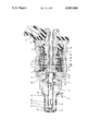
- FIGURE of the drawing is a cross section through a fuel injection valve according to the invention.
- a fuel injection valve has a valve housing 1 in which are located a coil carrier 2 and a magnetic coil 3. Electric current is carried to the magnetic coil 3 through a plug connection 4 embedded in a plastic ring 5.
- a non-magnetic bushing 6 one of whose ends is welded or soldered to a connection tube 7 through which gasoline is admitted to the valve and its other end is connected in the same manner with a housing extension 8 forming part of the valve housing 1.
- the housing extension 8 has a cylindrical collar 10 whose inside and outside diameters are the same as those of the non-magnetic bushing 6 so that the seal between the two members is smooth on both the inside and the outside.
- An arresting plate 12 of a particular thickness chosen for the exact adjustment of the valve rests on an interior shoulder 13 of the housing extension 8. Disposed between this arresting plate 12 and an axial end face of the connection tube 7 is located an armature 14 of the magnetic valve.
- the armature 14 consists of a corrosion resistant material.
- a compression spring 16 is located within the bore of the connection tube 7 and between an end face of the tube insert 15 and an end face of the armature 14 and tends to move the armature away from the connection tube 7.
- a valve needle 17 equipped with annular lands and grooves 18 is press-fit in a bore 19 on the opposite end of the armature 14.
- the valve needle 17 penetrates with clearance a bore 20 within the arresting plate 12 and a further bore 21 within the nozzle body 9 and its tip 22 extends out of the nozzle body 9.
- An interior shoulder 23 of the nozzle body has a conical valve seat surface 24 which cooperates with an exterior conical surface 25 on the valve needle 17, thereby forming the fuel injection valve 24/25.
- a protective sleeve 26 Surrounding the nozzle body 9 and the needle tip 22 is a protective sleeve 26, made of plastic and press-fit onto the nozzle body 9.
- the length of the valve needle 17 and of the armature 14 is so chosen that, when the valve is not actuated, a clearance A obtains between its upper face and the face 11 of the connection tube 7.
- a seal 27 is formed near an exterior shoulder 28 of the nozzle body by providing the nozzle body 9 with three annular edges 29 which are engaged by the outer edge 30 of the housing extension 8 which is pressed over them by a suitable tool, for example a crimping or roller tool. In this process, the sealing edges 29 embed themselves into the interior wall of the housing extension 8, thereby forming a reliable metal-to-metal seal.
- Two further seals 31 and 32 of the injection valve are provided at the respective ends of the non-magnetic sleeve 6. These seals are also metal-to-metal seals and thus are reliable and age-resistant. These seals 31 and 32 are formed either by welding or by soldering or, again, by the insertion of soft iron or copper ring seals. Due to this construction, even very high temperature loads cannot affect the seals detrimentally. The fuel injection valve remains tight at all times and no fuel can leak into the engine compartment so that fires due to leaking fuel cannot occur.
- valve In order to prevent the formation of corrosion in the valve which might affect the seals, the valve is so constructed that all interior portions of it are bathed by fuel. According to the invention, this is done by providing a valve needle 17 without an axial bore as has been the custom, but rather with two sets of quadruple flats 33 and 34 which provide guidance for the needle within the bore 21 and also provide an axial passage for the fuel. In this manner, the fuel flows from the direction of the armature 14 through the radial clearance between the bore 20 and the needle 17 and over the exterior surface of the valve needle 17. In this manner, the entire exterior surface of the valve needle is bathed by flowing fuel.
Abstract
An electromagnetically actuated fuel injection valve includes a coaxial assembly of a connection tube, a bushing, a housing extension and a nozzle body. All seals between adjacent faces and edges of these elements are age-resistant metal-to-metal seals. The seal between the housing extension and the nozzle body is formed by pressing the overlapping end of the housing extension over annular edges on the nozzle body. The remaining seals are welds or solder-joints.
Description
The invention relates to an electromagnetic periodically actuated injection valve for low pressure fuel injection systems of internal combustion engines. The fuel injection valve is used with induction tube injection and includes a housing, a locally fixed magnetic winding carried by an iron core and a coaxial movable armature. The armature, in turn, carries a valve needle which is guided within the nozzle body and is suitably fastened within the armature.
Valves of the type described above commonly use rubber seals, usually O-rings, to seal off those portions of the valve housing which carry fuel from the exterior. However, these valves are normally installed in the induction manifold of internal combustion engines and thus are subjected to very high temperature loads; the local temperatures may vary between -30° C and +130° C. Rubber or other elastic sealing elements cannot sustain such temperature loading for a very long time. Aging, shrinking and hardening, as well as the leaching of the softening agents by the aromatic components of gasoline soon lead to defective sealing properties of such rubber seals. The fuel lines are usually under a pressure of 2 to 3 bar so that fuel can leak from improperly sealed points of the valve into the engine compartment and may lead to a fire.
It is a principal object of the invention to provide an injection valve in which the disadvantage of improper and effective seals is avoided.
This object is attained, according to the invention, by providing an injection valve in which all seals are metal-to-metal seals.
The invention will be better understood as well as further objects and advantages thereof become more apparent from the following detailed description of a preferred embodiment taken in conjunction with the drawing.
The single FIGURE of the drawing is a cross section through a fuel injection valve according to the invention.
A fuel injection valve has a valve housing 1 in which are located a coil carrier 2 and a magnetic coil 3. Electric current is carried to the magnetic coil 3 through a plug connection 4 embedded in a plastic ring 5.
Within the magnetic coil 3 there is disposed a non-magnetic bushing 6 one of whose ends is welded or soldered to a connection tube 7 through which gasoline is admitted to the valve and its other end is connected in the same manner with a housing extension 8 forming part of the valve housing 1. The housing extension 8 has a cylindrical collar 10 whose inside and outside diameters are the same as those of the non-magnetic bushing 6 so that the seal between the two members is smooth on both the inside and the outside.
An arresting plate 12 of a particular thickness chosen for the exact adjustment of the valve, rests on an interior shoulder 13 of the housing extension 8. Disposed between this arresting plate 12 and an axial end face of the connection tube 7 is located an armature 14 of the magnetic valve. The armature 14 consists of a corrosion resistant material. Coaxially with and inside of an interior bore of the connection tube 7 lies a tube insert 15 which is fastened therein by crimping. A compression spring 16 is located within the bore of the connection tube 7 and between an end face of the tube insert 15 and an end face of the armature 14 and tends to move the armature away from the connection tube 7. A valve needle 17 equipped with annular lands and grooves 18 is press-fit in a bore 19 on the opposite end of the armature 14.
The valve needle 17 penetrates with clearance a bore 20 within the arresting plate 12 and a further bore 21 within the nozzle body 9 and its tip 22 extends out of the nozzle body 9. An interior shoulder 23 of the nozzle body has a conical valve seat surface 24 which cooperates with an exterior conical surface 25 on the valve needle 17, thereby forming the fuel injection valve 24/25. Surrounding the nozzle body 9 and the needle tip 22 is a protective sleeve 26, made of plastic and press-fit onto the nozzle body 9. The length of the valve needle 17 and of the armature 14 is so chosen that, when the valve is not actuated, a clearance A obtains between its upper face and the face 11 of the connection tube 7.
A seal 27 is formed near an exterior shoulder 28 of the nozzle body by providing the nozzle body 9 with three annular edges 29 which are engaged by the outer edge 30 of the housing extension 8 which is pressed over them by a suitable tool, for example a crimping or roller tool. In this process, the sealing edges 29 embed themselves into the interior wall of the housing extension 8, thereby forming a reliable metal-to-metal seal.
Two further seals 31 and 32 of the injection valve are provided at the respective ends of the non-magnetic sleeve 6. These seals are also metal-to-metal seals and thus are reliable and age-resistant. These seals 31 and 32 are formed either by welding or by soldering or, again, by the insertion of soft iron or copper ring seals. Due to this construction, even very high temperature loads cannot affect the seals detrimentally. The fuel injection valve remains tight at all times and no fuel can leak into the engine compartment so that fires due to leaking fuel cannot occur.
In order to prevent the formation of corrosion in the valve which might affect the seals, the valve is so constructed that all interior portions of it are bathed by fuel. According to the invention, this is done by providing a valve needle 17 without an axial bore as has been the custom, but rather with two sets of quadruple flats 33 and 34 which provide guidance for the needle within the bore 21 and also provide an axial passage for the fuel. In this manner, the fuel flows from the direction of the armature 14 through the radial clearance between the bore 20 and the needle 17 and over the exterior surface of the valve needle 17. In this manner, the entire exterior surface of the valve needle is bathed by flowing fuel.
Claims (4)
1. In an electromagnetic fuel injection valve for timed low-pressure fuel injection systems, which valve includes a coaxial assembly of a connection tube, a bushing, a housing extension and a fuel nozzle body, said assembly forming a substantially cylindrical passage for fuel to be delivered by said valve to an engine, the improvement comprising metallic seals between adjacent portions of said connection tube and said bushing, and between said bushing and said housing extension, said metallic seals having their surfaces in engagement with their corresponding adjacent elements under pressure, and a further metallic seal between said housing extension and said nozzle body, said further metallic seal being formed by parallel edges on said nozzle body which mate with an interior portion of said housing extension, and under external pressure embed themselves into the wall defining the interior portion of said housing extension.
2. A fuel injection valve as claimed in claim 1, wherein said bushing is a non-magnetic bushing disposed coaxially within the magnetic windings of said electromagnetic valve.
3. A fuel injection valve as claimed in claim 1, further including an armature, slidably disposed within a bore of said housing extension and a valve needle, fixedly and coaxially attached to said armature, the improvement further comprising said valve needle having a square transverse cross section in at least two separate locations; whereby fuel may flow over the flat exterior surfaces of said locations and over the remaining exterior surface of said valve needle.
4. A fuel injection valve as claimed in claim 1, wherein the metallic seals between adjacent portions of said connection tube and said bushing and between said bushing and said housing extension also serve to bond their respective adjacent elements to each other.
Applications Claiming Priority (2)
| Application Number | Priority Date | Filing Date | Title |
|---|---|---|---|
| DE19742458728 DE2458728A1 (en) | 1974-12-12 | 1974-12-12 | ELECTROMAGNETICALLY ACTIVATED INJECTION VALVE |
| DT2458728 | 1974-12-12 |
Publications (1)
| Publication Number | Publication Date |
|---|---|
| US4007880A true US4007880A (en) | 1977-02-15 |
Family
ID=5933197
Family Applications (1)
| Application Number | Title | Priority Date | Filing Date |
|---|---|---|---|
| US05/637,147 Expired - Lifetime US4007880A (en) | 1974-12-12 | 1975-12-03 | Electromagnetic fuel injection valve |
Country Status (4)
| Country | Link |
|---|---|
| US (1) | US4007880A (en) |
| JP (1) | JPS5854263B2 (en) |
| DE (1) | DE2458728A1 (en) |
| GB (1) | GB1503578A (en) |
Cited By (44)
| Publication number | Priority date | Publication date | Assignee | Title |
|---|---|---|---|---|
| US4101074A (en) * | 1976-06-17 | 1978-07-18 | The Bendix Corporation | Fuel inlet assembly for a fuel injection valve |
| US4232830A (en) * | 1978-11-01 | 1980-11-11 | The Bendix Corporation | Electromagnetic fuel injector |
| US4266729A (en) * | 1979-01-04 | 1981-05-12 | Robert Bosch Gmbh | Injection valve for fuel injection systems |
| US4274598A (en) * | 1978-02-18 | 1981-06-23 | Robert Bosch Gmbh | Electromagnetic fuel injection valve for internal combustion engines |
| US4313571A (en) * | 1979-10-05 | 1982-02-02 | Weber S.P.A. | Electromagnetically actuated injector for internal combustion engine |
| US4339082A (en) * | 1979-08-03 | 1982-07-13 | Alfa Romeo S.P.A. | Rapid transient electroinjector |
| US4342443A (en) * | 1979-10-26 | 1982-08-03 | Colt Industries Operating Corp | Multi-stage fuel metering valve assembly |
| US4360164A (en) * | 1979-10-19 | 1982-11-23 | Weber Carburatori Azienda Della Weber S.P.A. | Electromagnetically actuated fuel injection valve for internal combustion engines |
| US4384681A (en) * | 1978-11-01 | 1983-05-24 | The Bendix Corporation | Electromagnetic fuel injector |
| US4417694A (en) * | 1980-10-22 | 1983-11-29 | The Bendix Corporation | Injector valve with contoured valve seat and needle valve interface |
| US4508091A (en) * | 1979-10-26 | 1985-04-02 | Colt Industries Operating Corp | Fuel metering apparatus with multi-stage fuel metering valve assembly |
| US4589596A (en) * | 1980-01-03 | 1986-05-20 | Robert Bosch Gmbh | Nozzle for internal combustion engines |
| US4805837A (en) * | 1986-10-30 | 1989-02-21 | Allied Corporation | Injector with swirl chamber return |
| US4869429A (en) * | 1986-10-30 | 1989-09-26 | Allied Corporation | High pressure vortex injector |
| US4925111A (en) * | 1988-02-25 | 1990-05-15 | Robert Bosch Gmbh | Fuel injection valve |
| US4971291A (en) * | 1988-06-23 | 1990-11-20 | Weber S.R.L. | Electromagnetic fuel metering and atomizing valve |
| US5190223A (en) * | 1988-10-10 | 1993-03-02 | Siemens Automotive L.P. | Electromagnetic fuel injector with cartridge embodiment |
| US5241938A (en) * | 1990-03-14 | 1993-09-07 | Aisan Kogyo Kabushiki Kaisha | Injector with assist air passage for atomizing fuel |
| USRE34527E (en) * | 1989-11-09 | 1994-02-01 | Yamaha Hatsudoki Kabushiki Kaisha | Feeder wire structure for high pressure fuel injection unit |
| USRE34591E (en) * | 1989-11-09 | 1994-04-26 | Yamaha Hatsudoki Kabushiki Kaisha | High pressure fuel injection unit |
| US5307991A (en) * | 1990-10-09 | 1994-05-03 | Ford Motor Company | Fuel injector and method of manufacturing |
| US5375738A (en) * | 1993-10-27 | 1994-12-27 | Nordson Corporation | Apparatus for dispensing heated fluid materials |
| US5518185A (en) * | 1993-03-12 | 1996-05-21 | Nipponfrndo Co., Ltd. | Electromagnetic valve for fluid injection |
| US5535919A (en) * | 1993-10-27 | 1996-07-16 | Nordson Corporation | Apparatus for dispensing heated fluid materials |
| US5820031A (en) * | 1994-06-09 | 1998-10-13 | Robert Bosch Gmbh | Valve needle for an electromagnetically actuated valve |
| US5862996A (en) * | 1997-01-10 | 1999-01-26 | The Procter & Gamble Company | Laminar flow nozzle |
| US5875922A (en) * | 1997-10-10 | 1999-03-02 | Nordson Corporation | Apparatus for dispensing an adhesive |
| US6000638A (en) * | 1997-11-03 | 1999-12-14 | Caterpillar Inc. | Apparatus for strengthening a fuel injector tip member |
| US6267307B1 (en) * | 1997-12-12 | 2001-07-31 | Magneti Marelli France | Fuel injector with anti-scale ceramic coating for direct injection |
| US6386467B1 (en) | 1999-06-29 | 2002-05-14 | Aisan Kogyo Kabushiki Kaisha | Injectors |
| US6575142B2 (en) * | 2001-03-28 | 2003-06-10 | Robert Bosch Gmbh | High-pressure fuel system for internal combustion engines |
| US20030146308A1 (en) * | 2002-01-18 | 2003-08-07 | Yoshinori Yamashita | Fuel injection device having magnetic circuit to drive movable core |
| US20030164411A1 (en) * | 2001-01-30 | 2003-09-04 | Ferdinand Reiter | Fuel injection valve |
| US20040144423A1 (en) * | 2003-01-28 | 2004-07-29 | Everett William F. | Method and apparatus for flow control |
| US20040195278A1 (en) * | 2003-04-03 | 2004-10-07 | Nordson Corporation | Electrically-operated dispensing module |
| US20050001189A1 (en) * | 2003-06-03 | 2005-01-06 | Yoshiyuki Takamatsu | Normally open solenoid valve |
| US20050098665A1 (en) * | 2003-11-07 | 2005-05-12 | Mitsubishi Denki Kabushiki Kaisha | Fuel injection valve |
| EP1559903A1 (en) * | 2004-01-28 | 2005-08-03 | Siemens VDO Automotive S.p.A. | Fuel injector with deformable needle |
| US20050230438A1 (en) * | 2004-04-15 | 2005-10-20 | Nordson Corporation | Electrically-operated dispenser |
| US20060238354A1 (en) * | 2005-04-20 | 2006-10-26 | Nordson Corporation | Method of attaching rfid tags to substrates |
| US20090108102A1 (en) * | 2007-10-30 | 2009-04-30 | Denso Corporation | Injector |
| US20090159728A1 (en) * | 2007-12-25 | 2009-06-25 | Denso Corporation | Fuel injection valve for internal combustion engine |
| US20110259299A1 (en) * | 2007-02-23 | 2011-10-27 | Marc-Jean Derenthal | Fuel Injector |
| US9261049B2 (en) * | 2012-09-25 | 2016-02-16 | Enginetics, Llc | Two step metering solenoid for multi-physics fuel atomizer |
Families Citing this family (8)
| Publication number | Priority date | Publication date | Assignee | Title |
|---|---|---|---|---|
| DE2905099A1 (en) * | 1979-02-10 | 1980-08-14 | Bosch Gmbh Robert | Electromagnetic fuel injection valve - ensures that quantity of fuel injected into engine is linearly dependent on time for which it is open |
| DE3225180A1 (en) * | 1982-07-06 | 1984-01-12 | Robert Bosch Gmbh, 7000 Stuttgart | INJECTION VALVE |
| JPS60119363A (en) * | 1983-11-30 | 1985-06-26 | Keihin Seiki Mfg Co Ltd | Fuel injection valve |
| IT1226476B (en) * | 1987-03-12 | 1991-01-16 | Weber Srl | PROCEDURE AND EQUIPMENT TO CREATE INJECTOR VALVES FOR INTERNAL COMBUSTION ENGINES WITH IGNITION |
| DE3834446A1 (en) * | 1988-10-10 | 1990-04-12 | Mesenich Gerhard | ELECTROMAGNETIC INJECTION VALVE IN CARTRIDGE DESIGN |
| DE4237405C3 (en) * | 1991-12-17 | 2003-10-30 | Mitsubishi Electric Corp | Fuel injection device for an internal combustion engine and method for producing a solid core for this injection device |
| JPH0668669U (en) * | 1993-03-16 | 1994-09-27 | 有限会社藤井装飾 | Spare blade type cutter knife |
| US5975437A (en) * | 1997-11-03 | 1999-11-02 | Caterpillar, Inc. | Fuel injector solenoid utilizing an apertured armature |
Citations (4)
| Publication number | Priority date | Publication date | Assignee | Title |
|---|---|---|---|---|
| US3139785A (en) * | 1961-08-30 | 1964-07-07 | Wedgelock Corp Of California | Axial load bearing anchoring means for fastener pins |
| US3439876A (en) * | 1966-06-06 | 1969-04-22 | Murphy Diesel Co | Check valve assembly for engine fuel injectors |
| US3442491A (en) * | 1966-01-25 | 1969-05-06 | Friedrich Messerschmidt | Needle type fuel injection assembly |
| US3828247A (en) * | 1972-06-28 | 1974-08-06 | Volkswagenwerk Ag | Testing a fuel injection valve |
-
1974
- 1974-12-12 DE DE19742458728 patent/DE2458728A1/en not_active Withdrawn
-
1975
- 1975-05-02 GB GB18334/75A patent/GB1503578A/en not_active Expired
- 1975-12-03 US US05/637,147 patent/US4007880A/en not_active Expired - Lifetime
- 1975-12-11 JP JP50147886A patent/JPS5854263B2/en not_active Expired
Patent Citations (4)
| Publication number | Priority date | Publication date | Assignee | Title |
|---|---|---|---|---|
| US3139785A (en) * | 1961-08-30 | 1964-07-07 | Wedgelock Corp Of California | Axial load bearing anchoring means for fastener pins |
| US3442491A (en) * | 1966-01-25 | 1969-05-06 | Friedrich Messerschmidt | Needle type fuel injection assembly |
| US3439876A (en) * | 1966-06-06 | 1969-04-22 | Murphy Diesel Co | Check valve assembly for engine fuel injectors |
| US3828247A (en) * | 1972-06-28 | 1974-08-06 | Volkswagenwerk Ag | Testing a fuel injection valve |
Cited By (60)
| Publication number | Priority date | Publication date | Assignee | Title |
|---|---|---|---|---|
| US4101074A (en) * | 1976-06-17 | 1978-07-18 | The Bendix Corporation | Fuel inlet assembly for a fuel injection valve |
| US4274598A (en) * | 1978-02-18 | 1981-06-23 | Robert Bosch Gmbh | Electromagnetic fuel injection valve for internal combustion engines |
| US4384681A (en) * | 1978-11-01 | 1983-05-24 | The Bendix Corporation | Electromagnetic fuel injector |
| US4232830A (en) * | 1978-11-01 | 1980-11-11 | The Bendix Corporation | Electromagnetic fuel injector |
| US4266729A (en) * | 1979-01-04 | 1981-05-12 | Robert Bosch Gmbh | Injection valve for fuel injection systems |
| US4339082A (en) * | 1979-08-03 | 1982-07-13 | Alfa Romeo S.P.A. | Rapid transient electroinjector |
| US4313571A (en) * | 1979-10-05 | 1982-02-02 | Weber S.P.A. | Electromagnetically actuated injector for internal combustion engine |
| US4360164A (en) * | 1979-10-19 | 1982-11-23 | Weber Carburatori Azienda Della Weber S.P.A. | Electromagnetically actuated fuel injection valve for internal combustion engines |
| US4342443A (en) * | 1979-10-26 | 1982-08-03 | Colt Industries Operating Corp | Multi-stage fuel metering valve assembly |
| US4508091A (en) * | 1979-10-26 | 1985-04-02 | Colt Industries Operating Corp | Fuel metering apparatus with multi-stage fuel metering valve assembly |
| US4589596A (en) * | 1980-01-03 | 1986-05-20 | Robert Bosch Gmbh | Nozzle for internal combustion engines |
| US4417694A (en) * | 1980-10-22 | 1983-11-29 | The Bendix Corporation | Injector valve with contoured valve seat and needle valve interface |
| US4805837A (en) * | 1986-10-30 | 1989-02-21 | Allied Corporation | Injector with swirl chamber return |
| US4869429A (en) * | 1986-10-30 | 1989-09-26 | Allied Corporation | High pressure vortex injector |
| US4925111A (en) * | 1988-02-25 | 1990-05-15 | Robert Bosch Gmbh | Fuel injection valve |
| US4971291A (en) * | 1988-06-23 | 1990-11-20 | Weber S.R.L. | Electromagnetic fuel metering and atomizing valve |
| US5190223A (en) * | 1988-10-10 | 1993-03-02 | Siemens Automotive L.P. | Electromagnetic fuel injector with cartridge embodiment |
| USRE34527E (en) * | 1989-11-09 | 1994-02-01 | Yamaha Hatsudoki Kabushiki Kaisha | Feeder wire structure for high pressure fuel injection unit |
| USRE34591E (en) * | 1989-11-09 | 1994-04-26 | Yamaha Hatsudoki Kabushiki Kaisha | High pressure fuel injection unit |
| US5241938A (en) * | 1990-03-14 | 1993-09-07 | Aisan Kogyo Kabushiki Kaisha | Injector with assist air passage for atomizing fuel |
| US5307991A (en) * | 1990-10-09 | 1994-05-03 | Ford Motor Company | Fuel injector and method of manufacturing |
| US5518185A (en) * | 1993-03-12 | 1996-05-21 | Nipponfrndo Co., Ltd. | Electromagnetic valve for fluid injection |
| US5535919A (en) * | 1993-10-27 | 1996-07-16 | Nordson Corporation | Apparatus for dispensing heated fluid materials |
| US5375738A (en) * | 1993-10-27 | 1994-12-27 | Nordson Corporation | Apparatus for dispensing heated fluid materials |
| US5820031A (en) * | 1994-06-09 | 1998-10-13 | Robert Bosch Gmbh | Valve needle for an electromagnetically actuated valve |
| US5862996A (en) * | 1997-01-10 | 1999-01-26 | The Procter & Gamble Company | Laminar flow nozzle |
| US5875922A (en) * | 1997-10-10 | 1999-03-02 | Nordson Corporation | Apparatus for dispensing an adhesive |
| US6000638A (en) * | 1997-11-03 | 1999-12-14 | Caterpillar Inc. | Apparatus for strengthening a fuel injector tip member |
| US6267307B1 (en) * | 1997-12-12 | 2001-07-31 | Magneti Marelli France | Fuel injector with anti-scale ceramic coating for direct injection |
| US6386467B1 (en) | 1999-06-29 | 2002-05-14 | Aisan Kogyo Kabushiki Kaisha | Injectors |
| US20030164411A1 (en) * | 2001-01-30 | 2003-09-04 | Ferdinand Reiter | Fuel injection valve |
| US6988681B2 (en) * | 2001-01-30 | 2006-01-24 | Robert Bosch Gmbh | Fuel injection valve |
| US6575142B2 (en) * | 2001-03-28 | 2003-06-10 | Robert Bosch Gmbh | High-pressure fuel system for internal combustion engines |
| US20030146308A1 (en) * | 2002-01-18 | 2003-08-07 | Yoshinori Yamashita | Fuel injection device having magnetic circuit to drive movable core |
| US6805310B2 (en) * | 2002-01-18 | 2004-10-19 | Denso Corporation | Fuel injection device having magnetic circuit to drive movable core |
| US7156115B2 (en) | 2003-01-28 | 2007-01-02 | Lancer Partnership, Ltd | Method and apparatus for flow control |
| US20040144423A1 (en) * | 2003-01-28 | 2004-07-29 | Everett William F. | Method and apparatus for flow control |
| US20040195278A1 (en) * | 2003-04-03 | 2004-10-07 | Nordson Corporation | Electrically-operated dispensing module |
| US6994234B2 (en) * | 2003-04-03 | 2006-02-07 | Nordson Corporation | Electrically-operated dispensing module |
| US20050001189A1 (en) * | 2003-06-03 | 2005-01-06 | Yoshiyuki Takamatsu | Normally open solenoid valve |
| US20050098665A1 (en) * | 2003-11-07 | 2005-05-12 | Mitsubishi Denki Kabushiki Kaisha | Fuel injection valve |
| US6981663B2 (en) * | 2003-11-07 | 2006-01-03 | Mitsubishi Denki Kabushiki Kaisha | Fuel injection valve |
| WO2005075812A1 (en) * | 2004-01-28 | 2005-08-18 | Siemens Vdo Automotive Spa | Fluid injector with deformable needle |
| US8662420B2 (en) | 2004-01-28 | 2014-03-04 | Continental Automotive Italy S.P.A. | Valve body and fluid injector with a valve body |
| EP1559903A1 (en) * | 2004-01-28 | 2005-08-03 | Siemens VDO Automotive S.p.A. | Fuel injector with deformable needle |
| US20070278329A1 (en) * | 2004-01-28 | 2007-12-06 | Alessandro Facchin | Valve Body And Fluid Injector With A Valve Body |
| US7178704B2 (en) | 2004-04-15 | 2007-02-20 | Nordson Corporation | Electrically-operated dispenser |
| US20050230438A1 (en) * | 2004-04-15 | 2005-10-20 | Nordson Corporation | Electrically-operated dispenser |
| US20060238354A1 (en) * | 2005-04-20 | 2006-10-26 | Nordson Corporation | Method of attaching rfid tags to substrates |
| US7414532B2 (en) | 2005-04-20 | 2008-08-19 | Nordson Corporation | Method of attaching RFID tags to substrates |
| US9200604B2 (en) * | 2007-02-23 | 2015-12-01 | Robert Bosch Gmbh | Fuel injector having press-fitting structures |
| US20110259299A1 (en) * | 2007-02-23 | 2011-10-27 | Marc-Jean Derenthal | Fuel Injector |
| US8100350B2 (en) * | 2007-10-30 | 2012-01-24 | Denso Corporation | Injector |
| US20090108102A1 (en) * | 2007-10-30 | 2009-04-30 | Denso Corporation | Injector |
| US7896262B2 (en) * | 2007-12-25 | 2011-03-01 | Denso Corporation | Fuel injection valve for internal combustion engine |
| US20090159728A1 (en) * | 2007-12-25 | 2009-06-25 | Denso Corporation | Fuel injection valve for internal combustion engine |
| US9261049B2 (en) * | 2012-09-25 | 2016-02-16 | Enginetics, Llc | Two step metering solenoid for multi-physics fuel atomizer |
| US9982643B2 (en) | 2012-09-25 | 2018-05-29 | Enginetics, Llc | Two step metering solenoid for multi-physics fuel atomizer |
| US10697415B2 (en) | 2012-09-25 | 2020-06-30 | Enginetics, Llc | Two step metering solenoid for fluid dispenser |
| US11073121B2 (en) | 2012-09-25 | 2021-07-27 | Enginetics, Llc | Two step metering solenoid for fluid dispenser |
Also Published As
| Publication number | Publication date |
|---|---|
| JPS5183930A (en) | 1976-07-22 |
| GB1503578A (en) | 1978-03-15 |
| DE2458728A1 (en) | 1976-06-24 |
| JPS5854263B2 (en) | 1983-12-03 |
Similar Documents
| Publication | Publication Date | Title |
|---|---|---|
| US4007880A (en) | Electromagnetic fuel injection valve | |
| US4266729A (en) | Injection valve for fuel injection systems | |
| RU2076940C1 (en) | Electromagnetic valve | |
| EP0561859B1 (en) | Fuel injector | |
| US4313571A (en) | Electromagnetically actuated injector for internal combustion engine | |
| US6341412B1 (en) | Methods of forming a sheath and plastic ring on a electromagnetically operated valve | |
| US5178362A (en) | Electromagnetically actuatable valve | |
| US5190221A (en) | Electromagnetically actuatable fuel injection valve | |
| US5069834A (en) | Method of manufacturing an electromagnetically actuatable valve | |
| KR100375041B1 (en) | Shell component to protect injector from corrosion | |
| US5330153A (en) | Electromagnetically operable valve | |
| US4519547A (en) | Injection valve | |
| KR20000069385A (en) | Fuel injection valve | |
| US5820099A (en) | Fluid migration inhibitor for fuel injectors | |
| GB2254108A (en) | Spring bias setting bush for an i.c.engine fuel injector. | |
| GB2125939A (en) | Electromagnetically actuable valve | |
| US4033507A (en) | Fuel injection valve | |
| US5862995A (en) | High pressure fluid passage sealing for internal combustion engine fuel injectors and method of making same | |
| RU98111759A (en) | VALVE INJECTOR FOR FUEL INJECTION | |
| US20030164411A1 (en) | Fuel injection valve | |
| GB2116256A (en) | Electromagnetically actuable fuel injection valve | |
| JPH10504628A (en) | Overmolded cover and method for fuel injector power train | |
| EP1193391A1 (en) | Coil system including a structure for preventing fluid from leaking therein | |
| GB2116255A (en) | Electromagnetically actuable fuel injection valve | |
| US9127633B2 (en) | Actuator arrangement |