US4019022A - Storage system for hot food trays - Google Patents
Storage system for hot food trays Download PDFInfo
- Publication number
- US4019022A US4019022A US05/573,078 US57307875A US4019022A US 4019022 A US4019022 A US 4019022A US 57307875 A US57307875 A US 57307875A US 4019022 A US4019022 A US 4019022A
- Authority
- US
- United States
- Prior art keywords
- trays
- tray
- module
- contacts
- food
- Prior art date
- Legal status (The legal status is an assumption and is not a legal conclusion. Google has not performed a legal analysis and makes no representation as to the accuracy of the status listed.)
- Expired - Lifetime
Links
Images


Classifications
-
- A—HUMAN NECESSITIES
- A47—FURNITURE; DOMESTIC ARTICLES OR APPLIANCES; COFFEE MILLS; SPICE MILLS; SUCTION CLEANERS IN GENERAL
- A47J—KITCHEN EQUIPMENT; COFFEE MILLS; SPICE MILLS; APPARATUS FOR MAKING BEVERAGES
- A47J39/00—Heat-insulated warming chambers; Cupboards with heating arrangements for warming kitchen utensils
- A47J39/006—Heat-insulated warming chambers; Cupboards with heating arrangements for warming kitchen utensils for either storing and preparing or for preparing food on serving trays, e.g. heating, thawing, preserving
-
- A—HUMAN NECESSITIES
- A47—FURNITURE; DOMESTIC ARTICLES OR APPLIANCES; COFFEE MILLS; SPICE MILLS; SUCTION CLEANERS IN GENERAL
- A47B—TABLES; DESKS; OFFICE FURNITURE; CABINETS; DRAWERS; GENERAL DETAILS OF FURNITURE
- A47B31/00—Service or tea tables, trolleys, or wagons
- A47B31/02—Service or tea tables, trolleys, or wagons with heating, cooling or ventilating means
- A47B2031/026—Service or tea tables, trolleys, or wagons with heating, cooling or ventilating means having warm and cold compartments
-
- Y—GENERAL TAGGING OF NEW TECHNOLOGICAL DEVELOPMENTS; GENERAL TAGGING OF CROSS-SECTIONAL TECHNOLOGIES SPANNING OVER SEVERAL SECTIONS OF THE IPC; TECHNICAL SUBJECTS COVERED BY FORMER USPC CROSS-REFERENCE ART COLLECTIONS [XRACs] AND DIGESTS
- Y10—TECHNICAL SUBJECTS COVERED BY FORMER USPC
- Y10S—TECHNICAL SUBJECTS COVERED BY FORMER USPC CROSS-REFERENCE ART COLLECTIONS [XRACs] AND DIGESTS
- Y10S165/00—Heat exchange
- Y10S165/918—Heated and cooled food cabinets and/or trays
- Y10S165/919—Wheeled
Definitions
- the present invention relates generally to tray storage systems and, more particularly, to a storage system for hot food trays which are individually removable from their storage container.
- a further object of the invention is to provide such an improved tray storage system which holds the trays firmly in place in the storage container.
- a related object of the invention is to provide such a tray storage system which maintains a reliable electrical connection between the trays and the storage container, even when the storage container is portable and subject to vibration and jolts.
- Still another object of the invention is to provide such an improved tray storage system which can be economically manufactured by vacuum forming, even when made large enough to hold ten or more trays carrying full meals.
- a still further object of the invention is to provide such an improved tray storage system which is suitable for use in a food service vehicle.
- FIG. 1 is a perspective view of a food service vehicle embodying the invention, with segments of the doors broken away to show the internal structure;
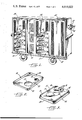
- FIG. 2 is a top perspective view of a food tray for use in the vehicle of FIG. 1;
- FIG. 3 is a bottom perspective of the food tray shown in FIG. 2;
- FIG. 4 is an exploded perspective of one of the tray storage modules in the vehicle of FIG. 1, with phantom lines illustrating the center section of the module as initially formed;
- FIG. 5 is an enlarged front elevation of one of the tray storage modules in the vehicle of FIG. 1;
- FIG. 6 is a vertical section taken along lines 6--6 in FIG. 5;
- FIG. 7 is a horizontal section taken along lines 7--7 in FIG. 5 and also showing the air blower that is used to ventilate the module and a fragment of the door which also forms a part of the ventilation system, and with arrows indicating the air flow pattern.
- FIG. 1 there is shown a food service vehicle containing three tray storage modules 10, 11 and 12 embodying the system of this invention.
- the particular vehicle illustrated is self propelled, with the manual drive controls located on a panel 13 carrying a pair of handles 14 which are used to steer the vehicle.
- a second control panel 15 on the side of the vehicle is used to control electrical heating elements which are embedded in each food tray 16 to heat preselected areas 17 and 18 (FIGS. 2 and 3) adapted to receive a hot plate and a soup bowl, respectively.
- the tray heating elements are connected to the metallic contacts 19 at the rear end of the bottom of the tray.
- Each tray 16 has a raised lip 20 extending around the entire periphery of the top surface of the tray, and a pair of runners 21 and 22 depending from the bottom of the tray.
- Each of the modules 10, 11 and 12 has the capacity of holding a number of different trays 16 which are inserted into the modules when they are opened by sliding one or more of the doors 23, 24 and 25 clear of their respective modules.
- a multiplicity of horizontal rails 26 and 27 are formed on the opposed side walls 28 and 29 thereof.
- At least one of the rails in each pair has an upwardly projecting lug near the front of the module for engaging a complementary notch in the bottom of the tray when the tray is fully inserted in the module, a plurality of guide surfaces are disposed above the rails for limiting vertical movement of the trays above the rails, and a plurality of electrical spring contacts engage the heater contacts at the rear end of the bottom of the tray to urge the rear of the tray upwardly against the guide surfaces and thereby urge the front of the tray downwardly toward the lugs to firmly latch the tray in position.
- each of the rails 26 on the right hand side walls 28 of each module forms a raised lug 30 which fits into a notch 31 or 32 (FIG. 3) formed in the runners of each tray 16.
- a tray is carrying hot food in the spaces 17 and 18, the tray is inserted with the heater contacts 19 at the rear of the storage module to connect the heaters to a power source housed behind the control panel 15. In this position, it is the notch 31 in the tray runner 21 that registers with the lug 30 to retain the tray within the module.
- the tray When the tray is carrying soiled dishes, or only cool food, it may be inserted into the module with the heater contacts 19 at the front of the module, in which the notch 32 in the tray runner 22 registers with the lug 30 to retain the tray within the module.
- the vertical shoulder formed by the rear side of the lug 30 cooperates with the complementary shoulder formed by the rear edge of one of the notches 31 and 32 to latch the tray in the module when the tray is fully inserted therein.
- the contacts engage a corresponding row of spring contacts 40 (FIGS. 4-7) mounted on a land 41 formed by the rear wall of the module. There is one land 41 for each tray station, and the spring contacts thereon are all connected to the on-board power source.
- the spring contacts 40 not only provide the desired electrical connections to the tray heater elements, but also urge the rear end of the tray upwardly against guiding surfaces 42 and 43 located above the respective rails 26 and 27. This elevates the rear end of the tray slightly above the rails 26 and 27, as can be seen in FIG. 6, thereby urging the forward end of the tray downwardly against the rails 26 and 27 to ensure a positive latch with the lug 30.
- the guiding surfaces 42 and 43 terminate forwardly of the spring contacts 40, so the surfaces 42 and 43 form a fulcrum located between the spring contacts 40 and the lug 30, on the opposite side of the tray from the lug 30, so that the forward end of the tray is pivoted downwardly against the lug 30.
- the space between each rail 26 or 27 and the adjacent guiding surface 42 or 43 must be slightly greater than the vertical demension of the tray to permit the runners 21 and 22 to slide over the lug 30 before one of the notches 31 or 32 comes into register with the lug 30.
- the spring contacts 40 are secured at one end to the front wall of the land 41 and at the other end to the top of the land 41, with the spring metal being bowed upwardly above the top of the land 41 to meet the tray contacts 19 as they are advanced over the spring contacts 40.
- the lower fasteners for the spring contacts 40 are connected to power lines 44 leading to the power source for energizing the tray heaters.
- the food trays are adapted to carry the hot food along one side wall of the storage module and the cool food along the other side wall
- a forced air inlet is provided in the rear wall of the module adjacent the side wall on the hot food side of the tray so that incoming forced air flows forwardly through the module with air outlet means adjacent the module side wall on the hot food side of the trays so that the forwardly flowing air exits through the door.
- the door also preferably forms fresh air intake means adjacent the module side wall on the cool food side of the trays so that the forwardly flowing forced air draws fresh air into the module and toward the rear wall of the module over the cool food on the trays.
- both heated areas 17 and 18 of the trays 16 are located on the same side of the tray so that when the tray is inserted into one of the storage modules with the electrical contacts at the rear of the module, the hot food is positioned along the right hand side wall 28.
- a blower 50 (FIG. 7) forces fresh air through a filter into a vertical plenum 51 mounted on the rear of each tray module. From the plenum 51, the forced air passes through an air inlet port 52 in the rear wall of the module adjacent the side wall on the hot food side of the tray. Consequently, the incoming forced air flows forwardly through the module over the hot food on the trays, with a diffuser 53 mounted in the inlet port 52 spreading the forced air over the two heated areas 17 and 18.
- the forced air exits through a grill 54 formed in the right hand side of the door 23.
- a grill 54 formed in the right hand side of the door 23.
- the grill 54 in the module door extends throughout the full height of the module, and a separate forced air inlet port 52 is provided at each tray station so that a separate forced air stream is formed between each pair of adjacent trays.
- the trays themselves serve as barriers to block the flow of heat in the vertical direction, but even if a tray is absent from a given station or stations, any heat that escapes upwardly from the forwardly flowing stream of forced air will encounter the forwardly flowing stream at the next air inlet before it can move laterally to the unheated side of the tray.
- the air inlet ports 52 are located above the normal level of the hot food dishes carried by the trays 16, so the forwardly flowing stream of forced air does not have any significant cooling effect on the hot dishes. Rather, the forced air stream picks up the heat that escapes above the hot dishes and carries that heat forwardly through the exit grill 54 so that the heat cannot move laterally to the unheated side of the tray.
- each of the three tray modules 10, 11 and 12 comprises vacuum formed top and bottom sections each forming a top or bottom wall of the module and portions of a rear wall and opposed side walls of the module, and a vacuum formed center section forming the balance of the rear and side walls of the module with the center section being folded at the corners of the rear and side walls.
- the bottom edge of the top section is bonded to the top edge of the center section, and the top edge of the bottom section is bonded to the bottom edge of the center section so as to form a unitary module from the three vaccum formed sections.
- the top section 60 of the tray module 10 is vacuum formed to form the top wall 61 of the module and top portions of the two side walls 28 and 29 and the rear wall. Cavities 62 and 63 are formed in opposite sides of the top section 60 to provide the two uppermost guiding surfaces 42 and 43.
- a bottom section 70 forms the bottom wall 71 of the module and lower ends of the side walls 28 and 29 and rear wall.
- Cavities 72 and 73 formed in the opposed side walls provide the lowermost pair of rails 26 and 27, and a cavity 74 in the rear wall forms the lowermost land 41 on which are mounted the lowermost set of spring contacts 40.
- the center section 80 of the module is initially formed with the rear wall and the two side walls 28 and 29 lying in a common plane, as illustrated in phantom lines in FIG. 4.
- the end portions thereof are folded perpendicular to the central portion so that the end portions form the opposed side walls 28 and 29 with the central portion forming the rear wall of the module.
- the initial vacuum formed article is folded along lines which become the rear corners of the module.
- a plurality of cavities 81 and 82 are formed in the side walls 28 and 29 so that the upper and lower surfaces of the resulting inner projections form the desired rails and guiding surfaces. More particularly, the upper surfaces of the projections formed by the cavities 81 form the guiderails 26 and the lugs 30, the lower surfaces of these same projections form the guiding surfaces 42, the upper surfaces of the projections formed by the cavities 82 form the rails 27, and the lower surfaces of these latter projections form the guiding surfaces 43. As shown most clearly in FIGS.
- the elongated vertical surfaces 83 and 84 of the respective cavities 81 and 82 are preferably formed with an ogee configuration so that the lower region of each tray compartment has a wider dimension than the upper region. This is desirable because most of the food containers carried by the trays extend upwardly into only the lower region of the tray compartment. Also, the runners 21 and 22 on the bottoms of the trays are spaced inwardly from the top peripheries of the trays so the guide rails 26 and 27 formed by the top surfaces of the projections must be wider than the guiding surfaces 42 and 43 formed by the lower surfaces thereof.
- a third series of cavities 85 are formed in the rear wall.
- the lands 41 formed by these cavities 85 are only slightly wider than the space occupied by the spring contacts 40, and the cavities form vertical front walls of sufficient height to form a rigid mounting surface for the lower ends of the spring contacts 40, and also to provide structural rigidity to the lands 41.
- the lower surfaces of the cavities 85 are spaced substantially above the top surfaces of the trays 16 so that they do not interfere with the food containers carried on the trays.
- the mating upper and lower edges of adjacent sections are provided with continuous lateral flanges which are rigidly bonded together by heat sealing, adhesives or the like.
- the bottom edge of the upper section 60 and the top edge of the center section 80 include outboard lateral flanges 86 and 87, respectively, extending continuously around the side and rear walls thereof.
- the top edge of the bottom section 70 and the bottom edge of the center section 80 include outboard lateral flanges 88 and 89, respectively, extending continuously around the side and rear walls.
- a lateral flange 90 also extends outwardly from the entire periphery of the module.
- This front flange 90 also conceals any gaps or rough surfaces in the interface between the module and the adjacent edges of the housing in which it is mounted. It will be recognized that it is a simple matter to form this flange 90 as an integral part of the three module sections 60, 70 and 80 during the vacuum forming operation.
- this invention provides an improved storage system for trays which contain both hot and cool foods, maintaining a maximum temperature differential between heated and unheated portions of the trays.
- This storage system holds the trays firmly in place in the storage container, while maintaining a reliable electrical connection between the trays and the storage container, even when the container is portable and subject to vibration and jolts.
- the entire system can be economically manufactured by vacuum forming, even when it is made large enough to hold ten or more trays carrying full meals.
- the system is particularly suitable for use in a food service vehicle.
Abstract
Description
Claims (3)
Priority Applications (1)
| Application Number | Priority Date | Filing Date | Title |
|---|---|---|---|
| US05/573,078 US4019022A (en) | 1975-04-30 | 1975-04-30 | Storage system for hot food trays |
Applications Claiming Priority (1)
| Application Number | Priority Date | Filing Date | Title |
|---|---|---|---|
| US05/573,078 US4019022A (en) | 1975-04-30 | 1975-04-30 | Storage system for hot food trays |
Publications (1)
| Publication Number | Publication Date |
|---|---|
| US4019022A true US4019022A (en) | 1977-04-19 |
Family
ID=24290549
Family Applications (1)
| Application Number | Title | Priority Date | Filing Date |
|---|---|---|---|
| US05/573,078 Expired - Lifetime US4019022A (en) | 1975-04-30 | 1975-04-30 | Storage system for hot food trays |
Country Status (1)
| Country | Link |
|---|---|
| US (1) | US4019022A (en) |
Cited By (44)
| Publication number | Priority date | Publication date | Assignee | Title |
|---|---|---|---|---|
| US4068115A (en) * | 1974-05-09 | 1978-01-10 | Sweetheart Plastics, Inc. | Food serving tray |
| US4156456A (en) * | 1976-07-09 | 1979-05-29 | Kreis Ag | Apparatus for the storage and for the preparing of foods, especially meals, to be served |
| US4194109A (en) * | 1977-01-11 | 1980-03-18 | Messer Griesheim Gmbh | Food serving tray and supporting heater shelf |
| US4203486A (en) * | 1977-01-11 | 1980-05-20 | Anchor Hocking Corporation | Food preparation apparatus and process |
| US4225204A (en) * | 1978-01-10 | 1980-09-30 | De Pruines Iseco | Cupboard for storing prepared meals, with cold-storage and reheating by microwaves |
| US4235282A (en) * | 1976-12-31 | 1980-11-25 | Filippis Modeste De | Heating and refrigerating tray cabinet for distributing hot and cold dishes |
| US4254824A (en) * | 1979-02-21 | 1981-03-10 | Anchor Hocking Corporation | Food preparation apparatus |
| US4285391A (en) * | 1979-08-29 | 1981-08-25 | Aladdin Industries, Incorporated | Electrical system for food service devices |
| US4323110A (en) * | 1977-01-11 | 1982-04-06 | Anchor Hocking Corporation | Food preparation process |
| US4386703A (en) * | 1977-12-15 | 1983-06-07 | Owens-Illinois, Inc. | Food service tray |
| EP0134929A1 (en) * | 1983-07-13 | 1985-03-27 | Lükon Fabrik für elektrothermische Apparate und elektrische Stabheizkörper Paul Lüscher | Apparatus for heating hot plates |
| US4560859A (en) * | 1984-08-10 | 1985-12-24 | Ptc Aerospace Inc. | Dish for use with meal tray feeding system which uses heater shelves to lift dishes |
| US4776386A (en) * | 1985-04-29 | 1988-10-11 | Hermann Meier | Apparatus for cooling, storing and reheating food using induction heating |
| WO1991012473A1 (en) * | 1990-02-16 | 1991-08-22 | Therma-Chill, Inc. | Improved rethermalization cart assembly |
| US5146065A (en) * | 1990-07-25 | 1992-09-08 | Jamco Corporation | Cart |
| US5182438A (en) * | 1990-01-11 | 1993-01-26 | Aladdin Synergetics, Inc. | Food service apparatus and process |
| USD334513S (en) | 1992-08-04 | 1993-04-06 | Aladdin Synergetics, Inc. | Cover |
| USD335796S (en) | 1990-01-29 | 1993-05-25 | Aladdin Synergetics, Inc. | Food serving tray |
| USD335797S (en) | 1992-07-08 | 1993-05-25 | Aladdin Synergetics, Inc. | Tray |
| USD336592S (en) | 1989-08-15 | 1993-06-22 | Aladdin Synergetics, Inc. | Tray top for a food service tray |
| US5403997A (en) * | 1989-08-15 | 1995-04-04 | Aladdin Synergetics, Inc. | Rethermalization system and cart |
| US5449232A (en) * | 1994-03-15 | 1995-09-12 | Standex International Corporation | Insulating barrier for combined hot/cold food service cart |
| US5454427A (en) * | 1992-11-23 | 1995-10-03 | Standex International Corporation | Rethermalization system having microcontroller computed start times and microcontrollers controlling heaters |
| US5771959A (en) * | 1992-11-23 | 1998-06-30 | Standex International Corporation | Rethermalization system |
| US5783803A (en) * | 1995-12-20 | 1998-07-21 | Robards, Jr.; Chester F. | Food warming apparatus |
| US5797445A (en) * | 1992-11-23 | 1998-08-25 | Standex International Corporation | Refrigerated rethermalization cart |
| US5852967A (en) * | 1997-02-03 | 1998-12-29 | Restaurant Technology, Inc. | Food treatment system |
| US5880434A (en) * | 1995-11-21 | 1999-03-09 | Restaurant Technology, Inc. | Food treatment cabinet |
| EP0937434A1 (en) * | 1998-02-19 | 1999-08-25 | Sataco Co., LTD. | Heat-reserving container for pizza and furnace for the same |
| US5947012A (en) * | 1995-05-11 | 1999-09-07 | Restaurant Technology, Inc. | Cooked food staging device and method |
| US6021709A (en) * | 1998-10-28 | 2000-02-08 | Henny Penny Corporation | Apparatus, system, and methods for preparing food products using high velocity air flow |
| US6234498B1 (en) * | 1997-12-05 | 2001-05-22 | Jamco Corporation | Rim member structure of service cart |
| US6259065B1 (en) | 1999-04-28 | 2001-07-10 | Henny Penny Corporation | Merchandisers with central heating and control mechanisms and methods for manufacturing and reconfiguring such merchandisers |
| US6414278B1 (en) * | 2000-03-21 | 2002-07-02 | Sigurd Frohlich | Pizza warmer and oven system |
| US20060045943A1 (en) * | 2004-08-31 | 2006-03-02 | Manuel Calzada | Food tray |
| WO2006092712A2 (en) * | 2005-03-04 | 2006-09-08 | S.A.G.I. - S.P.A. | Storage system for food trays |
| US20070278126A1 (en) * | 2006-06-01 | 2007-12-06 | Ashley Hatcher | Food Tray with Non-Slip Inserts |
| EP1894503A1 (en) * | 2006-08-30 | 2008-03-05 | Gronbach Forschungs- und Entwicklungs GmbH & Co. KG | Heated shelf |
| FR2957138A1 (en) * | 2010-03-03 | 2011-09-09 | Pierre Brossat | Fixed cabinet for e.g. preserving food product recipients in cold state, has control unit controlling operation of rethermalization system in subsequent rethermalization phase to assure consumption products rethermalization in enclosure |
| WO2017197216A1 (en) * | 2016-05-13 | 2017-11-16 | Carter-Hoffmann LLC | Transportable warming cart |
| CN108783924A (en) * | 2018-06-06 | 2018-11-13 | 利辛县风雅颂机电科技有限公司 | A kind of hand-push type dining car with damping |
| US10258197B1 (en) | 2015-07-17 | 2019-04-16 | Carter-Hoffmann LLC | Modular holding cabinet |
| WO2021126750A1 (en) * | 2019-12-20 | 2021-06-24 | Illinois Tool Works Inc. | Food thawing cabinet and related methods |
| US20220132892A1 (en) * | 2020-10-30 | 2022-05-05 | Illinois Tool Works Inc. | Food thawing cabinet and related methods |
Citations (11)
| Publication number | Priority date | Publication date | Assignee | Title |
|---|---|---|---|---|
| US1897879A (en) * | 1931-06-29 | 1933-02-14 | Roberts & Mander Stove Company | Safety device for electric ovens |
| US3097901A (en) * | 1961-01-16 | 1963-07-16 | Flure William R La | Molded drawers for modular storage facilities |
| US3175534A (en) * | 1963-11-15 | 1965-03-30 | Margaret E Pollard | Pet drying device |
| US3199579A (en) * | 1960-02-11 | 1965-08-10 | Foster Refrigerator Corp | Heating and cooling food storage cabinet |
| US3311434A (en) * | 1965-09-29 | 1967-03-28 | Crimsco Inc | Hot and cold food serving apparatus |
| US3387114A (en) * | 1965-06-09 | 1968-06-04 | Robert L. Brake Jr. | Warming oven |
| US3518949A (en) * | 1968-02-19 | 1970-07-07 | Arnold H Stock | Apparatus for conditioning dough and baked goods |
| US3836220A (en) * | 1972-09-20 | 1974-09-17 | N Ishammar | Goods delivery system |
| US3895215A (en) * | 1973-11-23 | 1975-07-15 | Jerry Dale Gordon | Cabinet for holding food at a controllable temperature |
| US3908749A (en) * | 1974-03-07 | 1975-09-30 | Standex Int Corp | Food service system |
| US3924100A (en) * | 1974-05-09 | 1975-12-02 | Anthony C Mack | Mobile food serving system |
-
1975
- 1975-04-30 US US05/573,078 patent/US4019022A/en not_active Expired - Lifetime
Patent Citations (11)
| Publication number | Priority date | Publication date | Assignee | Title |
|---|---|---|---|---|
| US1897879A (en) * | 1931-06-29 | 1933-02-14 | Roberts & Mander Stove Company | Safety device for electric ovens |
| US3199579A (en) * | 1960-02-11 | 1965-08-10 | Foster Refrigerator Corp | Heating and cooling food storage cabinet |
| US3097901A (en) * | 1961-01-16 | 1963-07-16 | Flure William R La | Molded drawers for modular storage facilities |
| US3175534A (en) * | 1963-11-15 | 1965-03-30 | Margaret E Pollard | Pet drying device |
| US3387114A (en) * | 1965-06-09 | 1968-06-04 | Robert L. Brake Jr. | Warming oven |
| US3311434A (en) * | 1965-09-29 | 1967-03-28 | Crimsco Inc | Hot and cold food serving apparatus |
| US3518949A (en) * | 1968-02-19 | 1970-07-07 | Arnold H Stock | Apparatus for conditioning dough and baked goods |
| US3836220A (en) * | 1972-09-20 | 1974-09-17 | N Ishammar | Goods delivery system |
| US3895215A (en) * | 1973-11-23 | 1975-07-15 | Jerry Dale Gordon | Cabinet for holding food at a controllable temperature |
| US3908749A (en) * | 1974-03-07 | 1975-09-30 | Standex Int Corp | Food service system |
| US3924100A (en) * | 1974-05-09 | 1975-12-02 | Anthony C Mack | Mobile food serving system |
Cited By (61)
| Publication number | Priority date | Publication date | Assignee | Title |
|---|---|---|---|---|
| US4068115A (en) * | 1974-05-09 | 1978-01-10 | Sweetheart Plastics, Inc. | Food serving tray |
| US4156456A (en) * | 1976-07-09 | 1979-05-29 | Kreis Ag | Apparatus for the storage and for the preparing of foods, especially meals, to be served |
| US4235282A (en) * | 1976-12-31 | 1980-11-25 | Filippis Modeste De | Heating and refrigerating tray cabinet for distributing hot and cold dishes |
| US4194109A (en) * | 1977-01-11 | 1980-03-18 | Messer Griesheim Gmbh | Food serving tray and supporting heater shelf |
| US4203486A (en) * | 1977-01-11 | 1980-05-20 | Anchor Hocking Corporation | Food preparation apparatus and process |
| US4323110A (en) * | 1977-01-11 | 1982-04-06 | Anchor Hocking Corporation | Food preparation process |
| US4386703A (en) * | 1977-12-15 | 1983-06-07 | Owens-Illinois, Inc. | Food service tray |
| US4225204A (en) * | 1978-01-10 | 1980-09-30 | De Pruines Iseco | Cupboard for storing prepared meals, with cold-storage and reheating by microwaves |
| US4254824A (en) * | 1979-02-21 | 1981-03-10 | Anchor Hocking Corporation | Food preparation apparatus |
| US4285391A (en) * | 1979-08-29 | 1981-08-25 | Aladdin Industries, Incorporated | Electrical system for food service devices |
| EP0134929A1 (en) * | 1983-07-13 | 1985-03-27 | Lükon Fabrik für elektrothermische Apparate und elektrische Stabheizkörper Paul Lüscher | Apparatus for heating hot plates |
| US4580035A (en) * | 1983-07-13 | 1986-04-01 | Lukon, Fabrik fur elektrothermische Apparate und elektrische Stabheizkorper | Apparatus for heating food-warmer plates |
| US4560859A (en) * | 1984-08-10 | 1985-12-24 | Ptc Aerospace Inc. | Dish for use with meal tray feeding system which uses heater shelves to lift dishes |
| US4776386A (en) * | 1985-04-29 | 1988-10-11 | Hermann Meier | Apparatus for cooling, storing and reheating food using induction heating |
| USD336592S (en) | 1989-08-15 | 1993-06-22 | Aladdin Synergetics, Inc. | Tray top for a food service tray |
| US5403997A (en) * | 1989-08-15 | 1995-04-04 | Aladdin Synergetics, Inc. | Rethermalization system and cart |
| US5182438A (en) * | 1990-01-11 | 1993-01-26 | Aladdin Synergetics, Inc. | Food service apparatus and process |
| USD335796S (en) | 1990-01-29 | 1993-05-25 | Aladdin Synergetics, Inc. | Food serving tray |
| WO1991012473A1 (en) * | 1990-02-16 | 1991-08-22 | Therma-Chill, Inc. | Improved rethermalization cart assembly |
| US5093556A (en) * | 1990-02-16 | 1992-03-03 | Therma-Chill, Inc. | Rethermalization cart assembly |
| US5396046A (en) * | 1990-02-16 | 1995-03-07 | Therma-Chill, Inc. | Rethermalization cart assembly |
| US5146065A (en) * | 1990-07-25 | 1992-09-08 | Jamco Corporation | Cart |
| USD335797S (en) | 1992-07-08 | 1993-05-25 | Aladdin Synergetics, Inc. | Tray |
| USD334513S (en) | 1992-08-04 | 1993-04-06 | Aladdin Synergetics, Inc. | Cover |
| US5454427A (en) * | 1992-11-23 | 1995-10-03 | Standex International Corporation | Rethermalization system having microcontroller computed start times and microcontrollers controlling heaters |
| US5771959A (en) * | 1992-11-23 | 1998-06-30 | Standex International Corporation | Rethermalization system |
| US5797445A (en) * | 1992-11-23 | 1998-08-25 | Standex International Corporation | Refrigerated rethermalization cart |
| US5868195A (en) * | 1992-11-23 | 1999-02-09 | Standex International Corporation | Rethermalization system |
| US5896915A (en) * | 1992-11-23 | 1999-04-27 | Standex International Corporation | Rethermalization system |
| US5449232A (en) * | 1994-03-15 | 1995-09-12 | Standex International Corporation | Insulating barrier for combined hot/cold food service cart |
| US6607766B2 (en) | 1995-05-11 | 2003-08-19 | Restaurant Technology, Inc. | Cooked food staging device and method |
| US6358548B1 (en) | 1995-05-11 | 2002-03-19 | Restaurant Technology, Inc. | Cooked food staging device and method |
| US5947012A (en) * | 1995-05-11 | 1999-09-07 | Restaurant Technology, Inc. | Cooked food staging device and method |
| US5880434A (en) * | 1995-11-21 | 1999-03-09 | Restaurant Technology, Inc. | Food treatment cabinet |
| US5783803A (en) * | 1995-12-20 | 1998-07-21 | Robards, Jr.; Chester F. | Food warming apparatus |
| US5852967A (en) * | 1997-02-03 | 1998-12-29 | Restaurant Technology, Inc. | Food treatment system |
| US6234498B1 (en) * | 1997-12-05 | 2001-05-22 | Jamco Corporation | Rim member structure of service cart |
| EP0937434A1 (en) * | 1998-02-19 | 1999-08-25 | Sataco Co., LTD. | Heat-reserving container for pizza and furnace for the same |
| US6021709A (en) * | 1998-10-28 | 2000-02-08 | Henny Penny Corporation | Apparatus, system, and methods for preparing food products using high velocity air flow |
| US6259065B1 (en) | 1999-04-28 | 2001-07-10 | Henny Penny Corporation | Merchandisers with central heating and control mechanisms and methods for manufacturing and reconfiguring such merchandisers |
| US6627855B2 (en) | 1999-04-28 | 2003-09-30 | Henny Penny Corporation | Merchandisers with central heating and control mechanisms and methods for manufacturing and reconfiguring such merchandisers |
| US6414278B1 (en) * | 2000-03-21 | 2002-07-02 | Sigurd Frohlich | Pizza warmer and oven system |
| US8974359B2 (en) | 2004-08-31 | 2015-03-10 | Restaurant Technology, Inc. | Food tray |
| US7901723B2 (en) * | 2004-08-31 | 2011-03-08 | Restaurant Technology, Inc. | Food tray |
| US20060045943A1 (en) * | 2004-08-31 | 2006-03-02 | Manuel Calzada | Food tray |
| WO2006092712A3 (en) * | 2005-03-04 | 2007-02-08 | G I S P A Sa | Storage system for food trays |
| WO2006092712A2 (en) * | 2005-03-04 | 2006-09-08 | S.A.G.I. - S.P.A. | Storage system for food trays |
| US8167129B2 (en) | 2006-06-01 | 2012-05-01 | Archer Innovations, Llc | Food tray with non-slip inserts |
| US7506763B2 (en) | 2006-06-01 | 2009-03-24 | Archer Innovations, Llc | Food tray with non-slip inserts |
| US20070278126A1 (en) * | 2006-06-01 | 2007-12-06 | Ashley Hatcher | Food Tray with Non-Slip Inserts |
| US20090139890A1 (en) * | 2006-06-01 | 2009-06-04 | Archer Innovations, Llc | Food tray with non-slip inserts |
| EP1894503A1 (en) * | 2006-08-30 | 2008-03-05 | Gronbach Forschungs- und Entwicklungs GmbH & Co. KG | Heated shelf |
| FR2957138A1 (en) * | 2010-03-03 | 2011-09-09 | Pierre Brossat | Fixed cabinet for e.g. preserving food product recipients in cold state, has control unit controlling operation of rethermalization system in subsequent rethermalization phase to assure consumption products rethermalization in enclosure |
| US10258197B1 (en) | 2015-07-17 | 2019-04-16 | Carter-Hoffmann LLC | Modular holding cabinet |
| US10408885B2 (en) | 2016-05-13 | 2019-09-10 | Carter-Hoffmann LLC | Transportable warming cart |
| WO2017197216A1 (en) * | 2016-05-13 | 2017-11-16 | Carter-Hoffmann LLC | Transportable warming cart |
| CN108783924A (en) * | 2018-06-06 | 2018-11-13 | 利辛县风雅颂机电科技有限公司 | A kind of hand-push type dining car with damping |
| CN108783924B (en) * | 2018-06-06 | 2021-06-25 | 苏州鹭翔航空设备有限公司 | Hand-push type dining car with damping mechanism |
| WO2021126750A1 (en) * | 2019-12-20 | 2021-06-24 | Illinois Tool Works Inc. | Food thawing cabinet and related methods |
| US11684076B2 (en) | 2019-12-20 | 2023-06-27 | Illinois Tool Works Inc. | Food thawing cabinet and related methods |
| US20220132892A1 (en) * | 2020-10-30 | 2022-05-05 | Illinois Tool Works Inc. | Food thawing cabinet and related methods |
Similar Documents
| Publication | Publication Date | Title |
|---|---|---|
| US4019022A (en) | Storage system for hot food trays | |
| US5228385A (en) | Convection oven for bakery goods | |
| US9677774B2 (en) | Multi-zone oven with variable cavity sizes | |
| US7025121B2 (en) | Refrigeration/rethermalization food delivery system | |
| US4386651A (en) | Heat exchanger accessory for electronic circuit cabinets | |
| US4180125A (en) | Apparatus for selectively heating an individual food item in a refrigerated environment | |
| US4515143A (en) | Moving air oven for baking and the like | |
| US9115903B2 (en) | Oven door | |
| US7655885B2 (en) | Oven | |
| US20110253698A1 (en) | High density universal holding cabinet | |
| US6886359B2 (en) | Showcase | |
| US4397159A (en) | Apparatus for chilling a plurality of food trays | |
| JPS6091143A (en) | Heat-insulating cabinet | |
| KR20060128067A (en) | Oven | |
| US4399667A (en) | Apparatus for chilling a plurality of food trays | |
| EP0080313B1 (en) | Apparatus for chilling food on a plurality of food trays | |
| CN110115516A (en) | The multi-region oven of steam assist type cooking area with variable volume | |
| JPS59164826A (en) | Device for thermally treating food and spice | |
| WO2000055556A1 (en) | Novel barrier system for a rethermalization / refrigeration food delivery system | |
| US8635995B2 (en) | Oven having a uniform hot air flow in the preparation space | |
| US6069344A (en) | Convection feature for use in ovens | |
| US7019272B2 (en) | Wall mounted microwave oven having an exhaust ventilation system | |
| US3478193A (en) | Food service carts | |
| KR20110033072A (en) | Storing apparatus | |
| JP3685181B2 (en) | Manufacturing method of heat insulation cold distribution car |
Legal Events
| Date | Code | Title | Description |
|---|---|---|---|
| AS | Assignment |
Owner name: GNB BATTERIES INC., 1110 HIGHWAY 110, MENDOTA HEIG Free format text: ASSIGNMENT OF ASSIGNORS INTEREST.;ASSIGNOR:GOULD INC.,;REEL/FRAME:004213/0299 Effective date: 19840106 |
|
| AS | Assignment |
Owner name: CITIBANK, N.A. 641 LEXINGTON AVENUE NEW YORK NY 10 Free format text: SECURITY INTEREST;ASSIGNOR:GNB BATTERIES INC.;REEL/FRAME:004253/0176 Effective date: 19840406 |
|
| AS | Assignment |
Owner name: GNB INCORPORATED Free format text: RELEASED BY SECURED PARTY;ASSIGNOR:CITIBANK, N.A.;REEL/FRAME:004508/0472 Effective date: 19840406 |
|
| AS | Assignment |
Owner name: GNB INCORPORATED Free format text: RELEASED BY SECURED PARTY;ASSIGNOR:CITIBANK, N.A.;REEL/FRAME:005386/0504 Effective date: 19871021 |