US4036755A - Filter for cleaning lubricating oil in internal combustion engines - Google Patents
Filter for cleaning lubricating oil in internal combustion engines Download PDFInfo
- Publication number
- US4036755A US4036755A US05/642,568 US64256875A US4036755A US 4036755 A US4036755 A US 4036755A US 64256875 A US64256875 A US 64256875A US 4036755 A US4036755 A US 4036755A
- Authority
- US
- United States
- Prior art keywords
- filter
- channel
- housing
- oil
- bolt
- Prior art date
- Legal status (The legal status is an assumption and is not a legal conclusion. Google has not performed a legal analysis and makes no representation as to the accuracy of the status listed.)
- Expired - Lifetime
Links
- 239000010687 lubricating oil Substances 0.000 title claims abstract description 22
- 238000004140 cleaning Methods 0.000 title claims description 10
- 238000002485 combustion reaction Methods 0.000 title claims description 10
- 239000003921 oil Substances 0.000 claims abstract description 95
- 238000005192 partition Methods 0.000 claims description 18
- 238000004891 communication Methods 0.000 claims description 10
- 230000001050 lubricating effect Effects 0.000 claims description 3
- 238000007599 discharging Methods 0.000 claims 3
- 238000011144 upstream manufacturing Methods 0.000 claims 1
- 238000010276 construction Methods 0.000 description 4
- 239000007788 liquid Substances 0.000 description 4
- 230000000717 retained effect Effects 0.000 description 3
- 230000015572 biosynthetic process Effects 0.000 description 2
- 238000012986 modification Methods 0.000 description 2
- 230000004048 modification Effects 0.000 description 2
- 238000007789 sealing Methods 0.000 description 2
- 230000003068 static effect Effects 0.000 description 2
- 230000006978 adaptation Effects 0.000 description 1
- 238000001914 filtration Methods 0.000 description 1
- 239000007789 gas Substances 0.000 description 1
- 230000005484 gravity Effects 0.000 description 1
- 238000003780 insertion Methods 0.000 description 1
- 230000037431 insertion Effects 0.000 description 1
- 238000009434 installation Methods 0.000 description 1
- 238000005461 lubrication Methods 0.000 description 1
- 239000002184 metal Substances 0.000 description 1
- 239000010705 motor oil Substances 0.000 description 1
- 238000000926 separation method Methods 0.000 description 1
Images
Classifications
-
- F—MECHANICAL ENGINEERING; LIGHTING; HEATING; WEAPONS; BLASTING
- F01—MACHINES OR ENGINES IN GENERAL; ENGINE PLANTS IN GENERAL; STEAM ENGINES
- F01M—LUBRICATING OF MACHINES OR ENGINES IN GENERAL; LUBRICATING INTERNAL COMBUSTION ENGINES; CRANKCASE VENTILATING
- F01M11/00—Component parts, details or accessories, not provided for in, or of interest apart from, groups F01M1/00 - F01M9/00
- F01M11/03—Mounting or connecting of lubricant purifying means relative to the machine or engine; Details of lubricant purifying means
-
- B—PERFORMING OPERATIONS; TRANSPORTING
- B01—PHYSICAL OR CHEMICAL PROCESSES OR APPARATUS IN GENERAL
- B01D—SEPARATION
- B01D27/00—Cartridge filters of the throw-away type
- B01D27/08—Construction of the casing
-
- B—PERFORMING OPERATIONS; TRANSPORTING
- B01—PHYSICAL OR CHEMICAL PROCESSES OR APPARATUS IN GENERAL
- B01D—SEPARATION
- B01D27/00—Cartridge filters of the throw-away type
- B01D27/10—Safety devices, e.g. by-passes
-
- B—PERFORMING OPERATIONS; TRANSPORTING
- B01—PHYSICAL OR CHEMICAL PROCESSES OR APPARATUS IN GENERAL
- B01D—SEPARATION
- B01D29/00—Filters with filtering elements stationary during filtration, e.g. pressure or suction filters, not covered by groups B01D24/00 - B01D27/00; Filtering elements therefor
- B01D29/11—Filters with filtering elements stationary during filtration, e.g. pressure or suction filters, not covered by groups B01D24/00 - B01D27/00; Filtering elements therefor with bag, cage, hose, tube, sleeve or like filtering elements
- B01D29/13—Supported filter elements
- B01D29/15—Supported filter elements arranged for inward flow filtration
-
- B—PERFORMING OPERATIONS; TRANSPORTING
- B01—PHYSICAL OR CHEMICAL PROCESSES OR APPARATUS IN GENERAL
- B01D—SEPARATION
- B01D29/00—Filters with filtering elements stationary during filtration, e.g. pressure or suction filters, not covered by groups B01D24/00 - B01D27/00; Filtering elements therefor
- B01D29/50—Filters with filtering elements stationary during filtration, e.g. pressure or suction filters, not covered by groups B01D24/00 - B01D27/00; Filtering elements therefor with multiple filtering elements, characterised by their mutual disposition
- B01D29/52—Filters with filtering elements stationary during filtration, e.g. pressure or suction filters, not covered by groups B01D24/00 - B01D27/00; Filtering elements therefor with multiple filtering elements, characterised by their mutual disposition in parallel connection
- B01D29/54—Filters with filtering elements stationary during filtration, e.g. pressure or suction filters, not covered by groups B01D24/00 - B01D27/00; Filtering elements therefor with multiple filtering elements, characterised by their mutual disposition in parallel connection arranged concentrically or coaxially
-
- B—PERFORMING OPERATIONS; TRANSPORTING
- B01—PHYSICAL OR CHEMICAL PROCESSES OR APPARATUS IN GENERAL
- B01D—SEPARATION
- B01D29/00—Filters with filtering elements stationary during filtration, e.g. pressure or suction filters, not covered by groups B01D24/00 - B01D27/00; Filtering elements therefor
- B01D29/88—Filters with filtering elements stationary during filtration, e.g. pressure or suction filters, not covered by groups B01D24/00 - B01D27/00; Filtering elements therefor having feed or discharge devices
- B01D29/92—Filters with filtering elements stationary during filtration, e.g. pressure or suction filters, not covered by groups B01D24/00 - B01D27/00; Filtering elements therefor having feed or discharge devices for discharging filtrate
- B01D29/925—Filters with filtering elements stationary during filtration, e.g. pressure or suction filters, not covered by groups B01D24/00 - B01D27/00; Filtering elements therefor having feed or discharge devices for discharging filtrate containing liquid displacement elements or cores
-
- B—PERFORMING OPERATIONS; TRANSPORTING
- B01—PHYSICAL OR CHEMICAL PROCESSES OR APPARATUS IN GENERAL
- B01D—SEPARATION
- B01D35/00—Filtering devices having features not specifically covered by groups B01D24/00 - B01D33/00, or for applications not specifically covered by groups B01D24/00 - B01D33/00; Auxiliary devices for filtration; Filter housing constructions
- B01D35/14—Safety devices specially adapted for filtration; Devices for indicating clogging
- B01D35/153—Anti-leakage or anti-return valves
-
- B—PERFORMING OPERATIONS; TRANSPORTING
- B01—PHYSICAL OR CHEMICAL PROCESSES OR APPARATUS IN GENERAL
- B01D—SEPARATION
- B01D35/00—Filtering devices having features not specifically covered by groups B01D24/00 - B01D33/00, or for applications not specifically covered by groups B01D24/00 - B01D33/00; Auxiliary devices for filtration; Filter housing constructions
- B01D35/16—Cleaning-out devices, e.g. for removing the cake from the filter casing or for evacuating the last remnants of liquid
-
- F—MECHANICAL ENGINEERING; LIGHTING; HEATING; WEAPONS; BLASTING
- F01—MACHINES OR ENGINES IN GENERAL; ENGINE PLANTS IN GENERAL; STEAM ENGINES
- F01M—LUBRICATING OF MACHINES OR ENGINES IN GENERAL; LUBRICATING INTERNAL COMBUSTION ENGINES; CRANKCASE VENTILATING
- F01M1/00—Pressure lubrication
- F01M1/10—Lubricating systems characterised by the provision therein of lubricant venting or purifying means, e.g. of filters
- F01M2001/105—Lubricating systems characterised by the provision therein of lubricant venting or purifying means, e.g. of filters characterised by the layout of the purification arrangements
- F01M2001/1064—Lubricating systems characterised by the provision therein of lubricant venting or purifying means, e.g. of filters characterised by the layout of the purification arrangements comprising drains for oil to the carter, e.g. to recover spilled oil during change of filters
-
- Y—GENERAL TAGGING OF NEW TECHNOLOGICAL DEVELOPMENTS; GENERAL TAGGING OF CROSS-SECTIONAL TECHNOLOGIES SPANNING OVER SEVERAL SECTIONS OF THE IPC; TECHNICAL SUBJECTS COVERED BY FORMER USPC CROSS-REFERENCE ART COLLECTIONS [XRACs] AND DIGESTS
- Y10—TECHNICAL SUBJECTS COVERED BY FORMER USPC
- Y10S—TECHNICAL SUBJECTS COVERED BY FORMER USPC CROSS-REFERENCE ART COLLECTIONS [XRACs] AND DIGESTS
- Y10S210/00—Liquid purification or separation
- Y10S210/13—Part flow-full flow
Definitions
- the present invention relates to a filter for cleaning lubricating oil in internal combustion engines with a base provided with at least two separate passages or channels for the clean-oil and the dirty-oil, with a main-filter and fine-filter arranged in the filter housing and with a cover retained by a fastening bolt connected with the base.
- the present invention also relates to a filter housing for receiving at least one filter insert for filtering and cleaning lubricating oil, provided with a geodetically upper assembly opening in the installed position for the insertion and interchange of the filter insert and with a geodetically lower base or bottom in the installed condition, and in which the housing interior space is connected by way of two separate housing channels extending in the base or bottom part of the housing with one housing connection each for the feed or inlet of dirty oil and for the discharge or outlet of filtered, clean oil.
- the present invention is concerned with the task to provide a filter of the aforementioned type in which, without large structural expenditures, the filtered liquid can be conducted back out of the main filter and out of the fine independently of different pressures in the passages. Furthermore, with the filter construction of the present invention, an emptying of the oil in the filter housing is to be avoided during standstill of the engine.
- a deflection or partition pipe which extends concentrically to the bolt approximately over the entire length of the fine filter and which simultaneously separates the fine filter from the main filter, is so arranged that an annular space on the clean-oil side, which is formed by the deflection pipe and the fine filter, is in communication by way of the bolt with the passage or channel for the auxiliary-flow clean-oil, and in that a vertical or upright pipe connected with the base is provided between the deflection pipe and the bolt, through which the clean oil leaving the main filter flows into the passage for the main-flow clean-oil.
- the deflection or partition pipe which is located with a slight radial spacing adjacent the fine filter, may be extended upwardly up to a place disposed shortly below the cover and may be sealingly connected with the bolt whereas the vertical pipe may terminate shortly below this place.
- the thus-taken measures prevent in cooperation with a check valve arranged between the engine oil pump suction strainer and a filter, an outflow of the oil out of the filter housing and an emptying thereof and therewith the formation of an air cushion impairing the operability of the lubricating oil system as well as enable the rapid removal of gases which separate out of the oil on the inside of the filter housing.
- the main-filter and the fine-filter which are arranged coaxially to one another may form a unitary filter cartridge in order to enable a rapid and uncomplicated exchange of this filter element.
- a drainage bore which is kept closed by the bolt is arranged in the path for the dirty oil, by way of which is a direct connection of the dirty-oil-side with the auxiliary-flow clean-oil side can be established after removal of the bolt.
- the dirty oil thus reaches already during the loosening operation of the bolt, the oil pan or sump of the crankcase by way of the passage or channel for the auxiliary-flow clean-oil.
- the liquid level thereby drops on the dirty-oil side. If the bolt is now completely removed, then the clean oil side may also drain off whereby the entry of dirty oil on the clean-oil side is prevented by the higher liquid level and by the thus higher static pressure.
- a filter housing of the present invention is also characterized in that the filter insert is interchangeable through the upper assembly installation of the housing which is arranged essentially vertically in the installed position so that the servicing personnel is not hampered by draining oil which runs out.
- the present invention is therefore also concerned with the task to facilitate the servicing of the filter housing, i.e., to further facilitate the interchange of the filter inserts.
- This task is solved according to the present invention in an advantageous manner in that the housing interior space is connected with a housing connection separate from the housing connection for the feed or inlet of dirty oil by way of a drainage connection provided in the base or bottom part of the housing which is adapted to be closed off by means of a closure device adapted to be opened at will.
- the oil remaining in the housing interior space can be drained off prior to the exchange of the filter insert.
- the closure means is so coupled with the fastening means of the cover that during the disengagement of the fastening means, the drainage connection is necessarily opened up.
- the drainage connection could terminate, for example, in a housing connection of its own which is accessible from the outside.
- a housing connection for the outlet or discharge of clean oil which is separate from the housing connection for the feed or inlet of dirty oil, is adapted to be connected with a reservoir or sump for the lubricating oil.
- the reservoir or sump is structurally separate from the crankcase or is arranged laterally at the crankcase.
- an oil pan retained at the bottom side of the crankcase may serve in a known manner as sump or reservoir.
- the drainage connection is interconnected between the housing interior space and that housing channel which is connected with the housing connection adapted to be connected with the reservoir or sump.
- This arrangement offers the advantage that a separate housing connection for the drainage connection is dispensed with and the lubricating oil drained out of the filter housing is conducted into the reservoir or sump.
- an oil sucking-off or syphoning-off may be provided by way of the short connecting stub of the measuring stick for the oil level.
- the oil which is present in the filter housing is sucked-off by way of the drainage connection when the oil is sucked off.
- the oil in the filter housing thereby flows into the oil pan under the influence of gravity after the opening of the cover and is then sucked off by way of the short pipe stub of the measuring stick for the oil level.
- the drainage connection is interconnected between the housing channel for the inlet of dirty oil and a housing connection separate from the housing connection for the feed of the dirty oil. In this manner, one section of the housing channel for the feed or inlet of dirty oil operates as drainage connection when the closure device thereof is opened up.
- a particularly short channel dimension for the drainage connection is achieved in the filter housing according to the present invention in that the drainage connection is interconnected between the housing channel for the feed or inlet of dirty oil and that housing channel whose housing connection is adapted to be connected with the reservoir or sump.
- the interior space of the housing is traversed by a bolt whose lower end engages in a bore of the base or housing bottom. It is thereby advantageous that the lower bolt end extends through the drainage connection and is constructed as closure means. In this manner, a closure means for the drainage connection which is structurally separate from the bolt can be economized.
- the bolt may serve as fastening means for the cover.
- the bolt may also serve as discharge for the clean oil of a filter insert.
- a discharge channel for the clean oil is provided within the bolt whereby the bore provided in the bottom or base of the housing for the lower bolt end terminates in a housing channel for the outlet of the clean oil of this discharge channel.
- the arrangement is made in such a manner that a drainage channel communicating with the housing interior space terminates at a place in the bore which is traversed by the lower bolt end, when the bolt is brought into its operating position.
- Another object of the present invention resides in a filter for cleaning the lubricating oil in internal combustion engines, in which an emptying or drainage of the oil in the filter housing during standstill of the engine is avoided.
- a further object of the present invention resides in a filter for cleaning lubricating oil in internal combustion engines in which the filtered oil can be conducted back out of the main filter and out of the auxiliary filter, independently of any different pressures which may exist in the respective passages or channels.
- Still a further object of the present invention resides in a filter housing for accommodating a filter insert intended to filter lubricating oil which greatly facilitates the servicing of the filter housing, particularly as regards the exchange of the filter insert.
- a still further object of the present invention resides in a filter housing of the type described above in which the service personnel is not hampered by running-out oil during the exchange of the filter insert.
- Still another object of the present invention resides in a filter housing construction in which the oil that has remained in the housing interior space can be drained off prior to the exchange of the filter insert.
- Another object of the present invention resides in a filter for cleaning lubricating oil in internal combustion engines in which the formation of an air cushion impairing the operability of the lubricating oil system is minimized.
- a further object of the present invention resides in a filter structure which enables a rapid and uncomplicated exchange of a filter insert constituted by a filter cartridge element forming the main filter and the auxiliary, fine filter.
- Still a further object of the present invention resides in a filter for cleaning lubricating oil in internal combustion engines in which a mixing of dirty and clean oil within the area of the filter housing can be effectively prevented during the interchange of the filter cartridge.
- Still another object of the present invention resides in a filter housing which is simple in construction, minimizes the number of housing connections and reduces the length of the housing channels or passages in the housing required for the various functions.
- FIGURE is a somewhat schematic elevational view, shown in longitudinal cross section in the right-half, through a filter with main- and auxiliary-flow in accordance with the present invention.
- the filter generally designated by reference numeral 1 consists of a cylindrically formed, pot-shaped filter housing having a lower bottom or base 3 formed into a structural unit together with the filter housing 2, for example, by being formed in one piece therewith, and provided with an upper assembly opening 20.
- a cover 4, adapted to close off the assembly opening 20, is retained in its installed position by a coaxially disposed fastening bolt 5 extending through the entire filter housing 2 and screwed into the base 3.
- a housing chamber 21 disposed in the base or bottom portion 3 is in continuous open communication both with the housing interior space 15 as also--in a manner not shown in detail in the drawing--with a housing channel 12 provided in the base or bottom portion 3.
- the housing channel 12 terminates in a schematically illustrated housing connection 22 of the base or bottom 3, to which may be connected the pressure line of a lubricating oil pump.
- Two further schematically illustrated housing connections 23 and 24 of the base or bottom portion 3 are in communication with one separate housing channel 13 and 14 each, respectively.
- a vertical or upright pipe 11 is sealingly inserted with its lower end into a wide bore 25 terminating, respectively, in the housing interior space 15, on the one hand, and in the housing channel 14, on the other.
- the vertical pipe 11 is traversed with radial play by the bolt 5.
- the lower bolt end 27 of the bolt 5 is sealingly screwed into a narrower threaded bore 26 formed, for example, by an appropriate insert, aligned with the bolt 5 and disposed between the housing channels 13 and 14.
- the upper end of the bolt 5 which extends through the cover 4 closing off the assembly opening 20, is constructed as hexagonal bolt head 28 which clamps the cover 4 against the filter housing 2 under interposition of a seal.
- a unitary filter cartridge generally designated by reference numeral 8 having a main-flow filter-insert 6 and an auxiliary-flow filter-insert 7 is arranged in the filter housing 2 whereby the main filter 6 and the fine filter 7 are arranged disposed one above the other and whereby the main filter 6 faces the base or bottom part 3.
- a deflection or partition pipe 9 arranged concentrically to the bolt 5 is provided on the hollow-space-side of the fine filter 7, which extends over nearly the entire length of the fine filter 7--with a slight spacing from the fine filter--and is connected with the bolt 5 shortly below the cover 4 by way of a sealing ring 10.
- the vertical pipe 11 rigidly connected with the base or bottom portion 3, which is disposed between the bolt 5, on the one hand, and the deflection or partition pipe 9 and the main filter 6, on the other, is extended upwardly up to near the sealing ring 10.
- the base or bottom part 3 is provided with the three passages or channels 12, 13 and 14, of which the passage or channel 12 serves as dirty oil inlet, the passage or channel 13 as return for the clean-oil auxiliary-flow and the passage or channel 14 as return for the clean-oil main-flow.
- the upper, radially extending sheet metal cover of the filter cartridge 8 is supported at the cover 4 under interposition of an annular seal 29 while the lower, radially extending cover wall thereof is supported at the vertical pipe 11 by way of an annular seal 30.
- the filter inserts 6 and 7 through which the oil flows radially from the outside toward the inside, are sealed off with respect to one another by the annularly shaped partition wall 31 which is sealed off with respect to the bolt 5 by the deflection or partition pipe 9 arranged with a radial spacing both with respect to the filter cartridge 8 as also with respect to the vertical pipe 11 under interposition of the annular seal 10.
- the annular seal 10 thereby has a spacing in the direction of the bolt axis with respect to the cover 4 as also with respect to the upper open end of the vertical pipe 11, which is kept in each case relatively small so that the clean-oil-streams of the two filter inserts 6 and 7 are conducted past a geodetically upper place of the filter housing 2 in order to favor the air separation.
- the clean oil chamber 32 enclosed by the vertical pipe 11 and the main-flow filter-insert 6 is in open communication with the housing channel 14 by way of the open upper end of the vertical pipe 11.
- the housing connection 23 may be connected in any suitable manner with the oil pan or sump of the motor vehicle so that the clean-oil-flow of the auxiliary-flow filter insert 7 is conducted into the lubricating oil sump of the engine.
- the housing interior space 15 can be brought into communication with the housing connection 23 for the oil pan or sump by way of the drainage channel 19 in that the lower bolt end 27 is screwed out of the bore 26. In this manner, the oil present in the housing interior space 15 is necessarily drained off into the oil pan during the opening of the cover 4.
- the drainage channel 19 is interconnected between the housing chamber 21 and the housing channel 13. At its end opposite the housing chamber 21, the drainage channel 19 terminates in the bore 26 at a place which is kept closed by the bolt end 27, when the bolt is brought into its operating position in which it clamps the cover 4 against the filter housing 2. After removal of the bolt 5, the drainage channel 19 is in communication with the housing channel 13 by way of the bore 26.
- the bore 26 and the housing channel 14 form a second outlet or drainage connection for the vertical pipe 11 whereby it is avoided by the geodetically lower arrangement of the drainage channel 19 for the housing interior space 15 with respect to the housing channel 14 adapted to be connected with the lubricating places that dirty oil out of the housing interior space 15 can reach the housing channel 14 by way of the bore 26 and therewith the lubricating places.
- the filtered clean oil leaving the auxiliary fine filter 7 flows as auxiliary flow at first through the narrow annular space 16, then through the cross bore 17 of the bolt 5 into the longitudinal discharge bore 18 thereof, and finally into the passage or channel 13, from which the filtered oil of the auxiliary clean-oil stream flows off into the oil pan of the crankcase (not shown) whereas the clean oil leaving the main filter 6 flows by way of the annular space 32, the space formed between the deflection pipe 9 and the vertical pipe 11 and the space formed between the verticle pipe 11 and the bolt 5, into the passage or channel 14 which is in communication with the lubricating oil system, and more particularly with the places to be lubricated.
- the deflection or partition pipe 9 and the vertical pipe 11 are extended upwardly as far as shown in the drawing in order to keep as small as possible the air cushions forming under the cover 4 when shutting down the engine.
- the drainage channel 19 is in open communication at its right end with the chamber 21 while its left end terminates within the area of the bolt 5, whereby the drainage channel 19 is closed off by the bolt 5 itself, when the bolt 5, in the operating condition thereof, is screwed-in.
- the bolt 5 is disengaged and its lower bolt end 27 is screwed out of the lower threaded bore 26.
Abstract
A filter housing for accommodating at least one filter insert to filter lubricating oil, which is provided in the installed position with a geodetically upper assembly opening for inserting and interchanging the filter insert and with a geodetically lower base; the housing interior space is connected by way of two separate housing channels extending in the base, with one housing connection each for the inlet of dirty oil and for the outlet of clean oil; the housing interior space can also be connected with a housing connection separate from the housing connection for the inlet of dirty oil by way of a drainage connection adapted to be closed off by means of a closure device which can be opened at will.
Description
The present invention relates to a filter for cleaning lubricating oil in internal combustion engines with a base provided with at least two separate passages or channels for the clean-oil and the dirty-oil, with a main-filter and fine-filter arranged in the filter housing and with a cover retained by a fastening bolt connected with the base.
Additionally, the present invention also relates to a filter housing for receiving at least one filter insert for filtering and cleaning lubricating oil, provided with a geodetically upper assembly opening in the installed position for the insertion and interchange of the filter insert and with a geodetically lower base or bottom in the installed condition, and in which the housing interior space is connected by way of two separate housing channels extending in the base or bottom part of the housing with one housing connection each for the feed or inlet of dirty oil and for the discharge or outlet of filtered, clean oil.
The present invention is concerned with the task to provide a filter of the aforementioned type in which, without large structural expenditures, the filtered liquid can be conducted back out of the main filter and out of the fine independently of different pressures in the passages. Furthermore, with the filter construction of the present invention, an emptying of the oil in the filter housing is to be avoided during standstill of the engine.
The problems underlying these tasks are solved according to the present invention in that a deflection or partition pipe which extends concentrically to the bolt approximately over the entire length of the fine filter and which simultaneously separates the fine filter from the main filter, is so arranged that an annular space on the clean-oil side, which is formed by the deflection pipe and the fine filter, is in communication by way of the bolt with the passage or channel for the auxiliary-flow clean-oil, and in that a vertical or upright pipe connected with the base is provided between the deflection pipe and the bolt, through which the clean oil leaving the main filter flows into the passage for the main-flow clean-oil.
In a preferred embodiment according to the present invention, the deflection or partition pipe, which is located with a slight radial spacing adjacent the fine filter, may be extended upwardly up to a place disposed shortly below the cover and may be sealingly connected with the bolt whereas the vertical pipe may terminate shortly below this place.
The thus-taken measures prevent in cooperation with a check valve arranged between the engine oil pump suction strainer and a filter, an outflow of the oil out of the filter housing and an emptying thereof and therewith the formation of an air cushion impairing the operability of the lubricating oil system as well as enable the rapid removal of gases which separate out of the oil on the inside of the filter housing.
According to the present invention, the main-filter and the fine-filter which are arranged coaxially to one another, may form a unitary filter cartridge in order to enable a rapid and uncomplicated exchange of this filter element.
During the cartridge exchange, a mixing of dirty-oil and clean-oil within the area of the filter housing cannot be avoided with the prior art main- and auxiliary-filters. In order to eliminate this disadvantage in a simple manner, it is additionally proposed according to the present invention that a drainage bore which is kept closed by the bolt, is arranged in the path for the dirty oil, by way of which is a direct connection of the dirty-oil-side with the auxiliary-flow clean-oil side can be established after removal of the bolt.
The dirty oil thus reaches already during the loosening operation of the bolt, the oil pan or sump of the crankcase by way of the passage or channel for the auxiliary-flow clean-oil. The liquid level thereby drops on the dirty-oil side. If the bolt is now completely removed, then the clean oil side may also drain off whereby the entry of dirty oil on the clean-oil side is prevented by the higher liquid level and by the thus higher static pressure.
A filter housing of the present invention is also characterized in that the filter insert is interchangeable through the upper assembly installation of the housing which is arranged essentially vertically in the installed position so that the servicing personnel is not hampered by draining oil which runs out.
The present invention is therefore also concerned with the task to facilitate the servicing of the filter housing, i.e., to further facilitate the interchange of the filter inserts.
This task is solved according to the present invention in an advantageous manner in that the housing interior space is connected with a housing connection separate from the housing connection for the feed or inlet of dirty oil by way of a drainage connection provided in the base or bottom part of the housing which is adapted to be closed off by means of a closure device adapted to be opened at will.
In the filter housing according to the present invention, the oil remaining in the housing interior space can be drained off prior to the exchange of the filter insert.
In order to prevent that the emptying of the filter housing is forgotten prior to the exchange of the filter insert, it is advantageous in the filter housing according to the present invention that the closure means is so coupled with the fastening means of the cover that during the disengagement of the fastening means, the drainage connection is necessarily opened up.
The drainage connection could terminate, for example, in a housing connection of its own which is accessible from the outside.
In lubricating oil filters of internal combustion engines, for example, it is customary that a housing connection for the outlet or discharge of clean oil which is separate from the housing connection for the feed or inlet of dirty oil, is adapted to be connected with a reservoir or sump for the lubricating oil. With a dry-sump lubrication, the reservoir or sump is structurally separate from the crankcase or is arranged laterally at the crankcase. However, an oil pan retained at the bottom side of the crankcase may serve in a known manner as sump or reservoir.
It is advantageous in the filter housing according to the present invention that the drainage connection is interconnected between the housing interior space and that housing channel which is connected with the housing connection adapted to be connected with the reservoir or sump.
This arrangement offers the advantage that a separate housing connection for the drainage connection is dispensed with and the lubricating oil drained out of the filter housing is conducted into the reservoir or sump. For purposes of changing the oil of the internal combustion engine, an oil sucking-off or syphoning-off may be provided by way of the short connecting stub of the measuring stick for the oil level. In the filter housing according to the present invention also the oil which is present in the filter housing is sucked-off by way of the drainage connection when the oil is sucked off. The oil in the filter housing thereby flows into the oil pan under the influence of gravity after the opening of the cover and is then sucked off by way of the short pipe stub of the measuring stick for the oil level.
In a structurally advantageous construction of the filter housing according to the present invention, provision may be made additionally that the drainage connection is interconnected between the housing channel for the inlet of dirty oil and a housing connection separate from the housing connection for the feed of the dirty oil. In this manner, one section of the housing channel for the feed or inlet of dirty oil operates as drainage connection when the closure device thereof is opened up.
A particularly short channel dimension for the drainage connection is achieved in the filter housing according to the present invention in that the drainage connection is interconnected between the housing channel for the feed or inlet of dirty oil and that housing channel whose housing connection is adapted to be connected with the reservoir or sump.
In the filter housing according to the present invention, the interior space of the housing is traversed by a bolt whose lower end engages in a bore of the base or housing bottom. It is thereby advantageous that the lower bolt end extends through the drainage connection and is constructed as closure means. In this manner, a closure means for the drainage connection which is structurally separate from the bolt can be economized.
The bolt may serve as fastening means for the cover. In addition to this function or also alone by itself, the bolt may also serve as discharge for the clean oil of a filter insert. For this purpose, a discharge channel for the clean oil is provided within the bolt whereby the bore provided in the bottom or base of the housing for the lower bolt end terminates in a housing channel for the outlet of the clean oil of this discharge channel. In the filter housing according to the present invention, the arrangement is made in such a manner that a drainage channel communicating with the housing interior space terminates at a place in the bore which is traversed by the lower bolt end, when the bolt is brought into its operating position.
Accordingly, it is an object of the present invention to provide a filter for cleaning lubricating oil in internal combustion engines which avoids by simple means the aforementioned shortcomings and drawbacks encountered in the prior art.
Another object of the present invention resides in a filter for cleaning the lubricating oil in internal combustion engines, in which an emptying or drainage of the oil in the filter housing during standstill of the engine is avoided.
A further object of the present invention resides in a filter for cleaning lubricating oil in internal combustion engines in which the filtered oil can be conducted back out of the main filter and out of the auxiliary filter, independently of any different pressures which may exist in the respective passages or channels.
Still a further object of the present invention resides in a filter housing for accommodating a filter insert intended to filter lubricating oil which greatly facilitates the servicing of the filter housing, particularly as regards the exchange of the filter insert.
A still further object of the present invention resides in a filter housing of the type described above in which the service personnel is not hampered by running-out oil during the exchange of the filter insert.
Still another object of the present invention resides in a filter housing construction in which the oil that has remained in the housing interior space can be drained off prior to the exchange of the filter insert.
Another object of the present invention resides in a filter for cleaning lubricating oil in internal combustion engines in which the formation of an air cushion impairing the operability of the lubricating oil system is minimized.
A further object of the present invention resides in a filter structure which enables a rapid and uncomplicated exchange of a filter insert constituted by a filter cartridge element forming the main filter and the auxiliary, fine filter.
Still a further object of the present invention resides in a filter for cleaning lubricating oil in internal combustion engines in which a mixing of dirty and clean oil within the area of the filter housing can be effectively prevented during the interchange of the filter cartridge.
Still another object of the present invention resides in a filter housing which is simple in construction, minimizes the number of housing connections and reduces the length of the housing channels or passages in the housing required for the various functions.
These and other objects, features and advantages of the present invention will become more apparent from the following description when taken in connection with the accompanying drawing which shows, for purposes of illustration only, one embodiment in accordance with the present invention, and wherein:
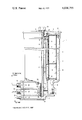
The single FIGURE is a somewhat schematic elevational view, shown in longitudinal cross section in the right-half, through a filter with main- and auxiliary-flow in accordance with the present invention.
Referring now to the single FIGURE of the drawing, the filter generally designated by reference numeral 1 consists of a cylindrically formed, pot-shaped filter housing having a lower bottom or base 3 formed into a structural unit together with the filter housing 2, for example, by being formed in one piece therewith, and provided with an upper assembly opening 20. A cover 4, adapted to close off the assembly opening 20, is retained in its installed position by a coaxially disposed fastening bolt 5 extending through the entire filter housing 2 and screwed into the base 3.
A housing chamber 21 disposed in the base or bottom portion 3 is in continuous open communication both with the housing interior space 15 as also--in a manner not shown in detail in the drawing--with a housing channel 12 provided in the base or bottom portion 3. The housing channel 12 terminates in a schematically illustrated housing connection 22 of the base or bottom 3, to which may be connected the pressure line of a lubricating oil pump. Two further schematically illustrated housing connections 23 and 24 of the base or bottom portion 3 are in communication with one separate housing channel 13 and 14 each, respectively. A vertical or upright pipe 11 is sealingly inserted with its lower end into a wide bore 25 terminating, respectively, in the housing interior space 15, on the one hand, and in the housing channel 14, on the other. The vertical pipe 11 is traversed with radial play by the bolt 5. The lower bolt end 27 of the bolt 5 is sealingly screwed into a narrower threaded bore 26 formed, for example, by an appropriate insert, aligned with the bolt 5 and disposed between the housing channels 13 and 14.
The upper end of the bolt 5 which extends through the cover 4 closing off the assembly opening 20, is constructed as hexagonal bolt head 28 which clamps the cover 4 against the filter housing 2 under interposition of a seal.
A unitary filter cartridge generally designated by reference numeral 8 having a main-flow filter-insert 6 and an auxiliary-flow filter-insert 7 is arranged in the filter housing 2 whereby the main filter 6 and the fine filter 7 are arranged disposed one above the other and whereby the main filter 6 faces the base or bottom part 3.
A deflection or partition pipe 9 arranged concentrically to the bolt 5 is provided on the hollow-space-side of the fine filter 7, which extends over nearly the entire length of the fine filter 7--with a slight spacing from the fine filter--and is connected with the bolt 5 shortly below the cover 4 by way of a sealing ring 10. The lower end 31 of the deflection or partition pipe 9, which extends radially, thereby separates the main filter 6 from the auxiliary, fine filter 7.
The vertical pipe 11 rigidly connected with the base or bottom portion 3, which is disposed between the bolt 5, on the one hand, and the deflection or partition pipe 9 and the main filter 6, on the other, is extended upwardly up to near the sealing ring 10.
The base or bottom part 3 is provided with the three passages or channels 12, 13 and 14, of which the passage or channel 12 serves as dirty oil inlet, the passage or channel 13 as return for the clean-oil auxiliary-flow and the passage or channel 14 as return for the clean-oil main-flow.
The upper, radially extending sheet metal cover of the filter cartridge 8 is supported at the cover 4 under interposition of an annular seal 29 while the lower, radially extending cover wall thereof is supported at the vertical pipe 11 by way of an annular seal 30.
The filter inserts 6 and 7 through which the oil flows radially from the outside toward the inside, are sealed off with respect to one another by the annularly shaped partition wall 31 which is sealed off with respect to the bolt 5 by the deflection or partition pipe 9 arranged with a radial spacing both with respect to the filter cartridge 8 as also with respect to the vertical pipe 11 under interposition of the annular seal 10. The annular seal 10 thereby has a spacing in the direction of the bolt axis with respect to the cover 4 as also with respect to the upper open end of the vertical pipe 11, which is kept in each case relatively small so that the clean-oil-streams of the two filter inserts 6 and 7 are conducted past a geodetically upper place of the filter housing 2 in order to favor the air separation.
The clean oil chamber 16 delimited by the partition or deflection pipe 10 and the auxiliary-flow filter-insert 7, is in communication by way of a cross-bore 17 of the bolt 5 with a discharge channel 18 extending on the inside of the bolt 5 and formed by an axial bore thereof, which extends through the lower bolt end 27 and as a result thereof is operatively connected with the housing channel 13.
In contradistinction thereto, the clean oil chamber 32 enclosed by the vertical pipe 11 and the main-flow filter-insert 6 is in open communication with the housing channel 14 by way of the open upper end of the vertical pipe 11.
The housing connection 23 may be connected in any suitable manner with the oil pan or sump of the motor vehicle so that the clean-oil-flow of the auxiliary-flow filter insert 7 is conducted into the lubricating oil sump of the engine.
The housing interior space 15 can be brought into communication with the housing connection 23 for the oil pan or sump by way of the drainage channel 19 in that the lower bolt end 27 is screwed out of the bore 26. In this manner, the oil present in the housing interior space 15 is necessarily drained off into the oil pan during the opening of the cover 4.
In the illustrated embodiment, the drainage channel 19 is interconnected between the housing chamber 21 and the housing channel 13. At its end opposite the housing chamber 21, the drainage channel 19 terminates in the bore 26 at a place which is kept closed by the bolt end 27, when the bolt is brought into its operating position in which it clamps the cover 4 against the filter housing 2. After removal of the bolt 5, the drainage channel 19 is in communication with the housing channel 13 by way of the bore 26. The bore 26 and the housing channel 14 form a second outlet or drainage connection for the vertical pipe 11 whereby it is avoided by the geodetically lower arrangement of the drainage channel 19 for the housing interior space 15 with respect to the housing channel 14 adapted to be connected with the lubricating places that dirty oil out of the housing interior space 15 can reach the housing channel 14 by way of the bore 26 and therewith the lubricating places.
The dirty oil fed by the oil pump (not shown) through the passage or channel 12 and chamber 21 into the annular space 15 formed by the filter cartridge 8 and the filter housing 2, enters into both filters 6 and 7. The filtered clean oil leaving the auxiliary fine filter 7 flows as auxiliary flow at first through the narrow annular space 16, then through the cross bore 17 of the bolt 5 into the longitudinal discharge bore 18 thereof, and finally into the passage or channel 13, from which the filtered oil of the auxiliary clean-oil stream flows off into the oil pan of the crankcase (not shown) whereas the clean oil leaving the main filter 6 flows by way of the annular space 32, the space formed between the deflection pipe 9 and the vertical pipe 11 and the space formed between the verticle pipe 11 and the bolt 5, into the passage or channel 14 which is in communication with the lubricating oil system, and more particularly with the places to be lubricated.
The flow direction of the dirty oil and the flow direction of the clean oil for the auxiliary flow out of the filter insert 7 and for the main flow out of the filter insert 6 are indicated by arrows.
The deflection or partition pipe 9 and the vertical pipe 11 are extended upwardly as far as shown in the drawing in order to keep as small as possible the air cushions forming under the cover 4 when shutting down the engine.
By reason of the fact that with the unitary filter cartridge 8 the filtered liquid can be conducted back separately out of the main filter 6 and out of the fine filter 7, a throttling during the through-flow through both the filters 6 and 7 can be selected freely--and more particularly separately for each filter--and thus an adaptation is possible to the pressure respectively prevailing in the main flow return and in the auxiliary flow return.
The drainage channel 19 is in open communication at its right end with the chamber 21 while its left end terminates within the area of the bolt 5, whereby the drainage channel 19 is closed off by the bolt 5 itself, when the bolt 5, in the operating condition thereof, is screwed-in.
During the cartridge exchange, the bolt 5 is disengaged and its lower bolt end 27 is screwed out of the lower threaded bore 26.
If the bolt 5 is unscrewed to the height of the bore 19, then a direct connection results between the annular space 15 and passage 21 on the side of the dirty oil, and the passage or channel 13 for the auxiliary-flow clean-oil. Thus, the dirty oil flows off into the engine sump by way of this channel or passage 13.
The already filtered oil on the clean-oil-side of the main filter 6 which, however, is disposed outside of the vertical pipe 11, flows back through the main filter 6 in the reverse direction and then also drains off by way of the annular space 15, the housing chamber 21, the drainage channel 19 and the passage or channel 13.
If the bolt 5 is further unscrewed and is removed, then also the oil on the clean oil side disposed on the inside of the vertical pipe 11 can drain off, however, an entry of the dirty oil into the channel or passage 14 is now precluded by the now higher level and by the therewith higher static pressure with respect to the dirty-oil-side.
While we have shown and described only one embodiment in accordance with the present invention, it is understood that the same is not limited thereto but is susceptible of numerous changes and modifications as known to those skilled in the art, and we therefore do not wish to be limited to the details shown and described herein but intend to cover all such changes and modifications as are encompassed by the scope of the appended claims.
Claims (23)
1. A filter for cleaning lubricating oil in internal combustion engines comprising
at least one filter insert means for cleaning lubricating oil, said filter insert means including a main filter and a fine filter arranged coaxially;
filter housing means for accommodating said filter insert means, said filter housing means comprising a housing member having (a) a hollow interior portion for accommodating said filter insert means, (b) an insert opening disposed at the top of said housing member for inserting said filter insert means, (c) a bottom portion closing off said hollow interior portion, said bottom portion including a plurality of separate channel means in operative communication with said hollow interior portion for respectively introducing dirty oil into said filter housing means and discharging clean oil from said filter housing means, and (d) cover means for covering said insert opening;
bolt means engaging said bottom portion for securing said cover means to said housing member, said bolt means including bore means axially extending from a geodetically upper portion of said housing member at said cover means to a geodetically lower portion of said housing member at said bottom portion for circulating auxiliary clean oil from said fine filter from said geodetically upper portion to a first of said plurality of separate channel means for discharging said auxiliary clean oil;
drainage connection means for operatively communicating said first channel means with said hollow interior portion separately from a second of said plurality of separate channel means for introducing said dirty oil, said drainage connection means being operatively closed off by an end portion of said bolt means at said bottom portion, wherein, upon moving said end portion to open said drainage connection means, oil from said hollow interior portion drains through said first channel means;
partition pipe means extending approximately over the entire length of said fine filter for conducting said auxiliary clean oil from said fine filter to said bore means at said geodetically upper portion; and
upright pipe means provided between said partition pipe means and said bolt means for conducting main clean oil from said main filter to a third of said plurality of separate channel means for discharging said main clean oil, said upright pipe means extending from approximately said geodetically upper portion and being connected to said bottom portion so that said main clean oil flows from said approximately geodetically upper portion to said third channel means separately from said second channel means.
2. A filter according to claim 1, wherein said fine filter is coaxially arranged above said main filter.
3. A filter according to claim 1, wherein said housing member is cylindrical.
4. A filter according to claim 1, wherein said drainage connection means communicates said first channel means with said hollow interior portion upstream of said filter insert means in the direction of flow of dirty oil from said second channel means.
5. A filter according to claim 1, wherein said drainage connection means includes a bore in said bottom portion extending from said hollow interior portion to a threaded bore in said bottom portion, said end portion of said bolt means threadedly engaging said threaded bore such that said drainage connection means is closed off.
6. A filter according to claim 5, wherein said bore of said drainage connection means opens into said threaded bore geodetically above said first channel means.
7. A filter according to claim 1, wherein said partition pipe means forms an annular space with said fine filter means through which said auxiliary clean oil flows to said bore means.
8. A filter according to claim 1, wherein said upright pipe means forms a first annular space with said partition pipe means through which first annular space said main clean oil flows upwardly to the end of said upright pipe means near said geodetically upper portion, and a second annular space with said bolt means through which second annular space said main clean oil flows downwardly to said third channel means.
9. A filter according to claim 1, wherein said third channel means are arranged in said bottom portion geodetically above said second channel means.
10. A filter according to claim 1, wherein said partition pipe means extends substantially concentrically to said bolt means.
11. A filter according to claim 1, wherein said partition pipe means includes a portion separating said fine filter from said main filter.
12. A filter according to claim 1, wherein said partition pipe means is disposed with a radial spacing adjacent said fine filter, extends upwardly up to a place located slightly below said cover means, and is sealingly connected with said bolt means, and wherein said upright pipe means terminates slightly below said place.
13. A filter according to claim 12, wherein said main filter and fine filter form a one-piece filter cartridge.
14. A filter according to claim 13, wherein said partition pipe means includes a portion separating said fine filter from said main filter.
15. A filter according to claim 1, wherein said main filter and fine filter form a one-piece filter cartridge.
16. A filter according to claim 1, wherein said first channel means is connected to a housing connection means for connecting said first channel means with a sump for lubricating oil.
17. A filter according to claim 1, wherein said third channel means is connected to a housing connection means for conducting lubricating oil to lubricating places, and wherein said drainage connection means is separate from said third channel means.
18. A filter according to claim 1, wherein said third channel means communicates with said first channel means upon moving said end portion of said bolt means from said bottom portion such that the main clean oil also drains through said first channel means when said bolt means is disengaged from said bottom portion.
19. A filter according to claim 18, wherein said third channel means are arranged geodetically above said first channel means and said drainage connection means communicating with said first channel means.
20. A filter according to claim 19, wherein said drainage connection means includes a bore in said bottom portion extending from said hollow interior portion to a threaded bore in said bottom portion, said end portion of said bolt means threadedly engaging said threaded bore such that said drainage connection means is closed off.
21. A filter according to claim 20, wherein said bore of said drainage connection means opens into said threaded bore geodetically above said first channel means.
22. A filter according to claim 20, wherein said upright pipe means forms a first annular space with said partition pipe means through which first annular space said main clean oil flows upwardly to the end of said upright pipe means near said geodetically upper portion, and a second annular space with said bolt means through which second annular space said main clean oil flows downwardly to said third channel means.
23. A filter according to claim 22, wherein said upright pipe means is secured to said bottom portion concentrically surrounding said bolt means at said threaded bore so that said second annular space communicates with said threaded bore upon removal of said end portion of said bolt means from said threaded bore.
Applications Claiming Priority (2)
| Application Number | Priority Date | Filing Date | Title |
|---|---|---|---|
| DT2460073 | 1974-12-19 | ||
| DE19742460073 DE2460073C3 (en) | 1974-12-19 | Filters for cleaning lubricating oil in internal combustion engines |
Publications (1)
| Publication Number | Publication Date |
|---|---|
| US4036755A true US4036755A (en) | 1977-07-19 |
Family
ID=5933820
Family Applications (1)
| Application Number | Title | Priority Date | Filing Date |
|---|---|---|---|
| US05/642,568 Expired - Lifetime US4036755A (en) | 1974-12-19 | 1975-12-19 | Filter for cleaning lubricating oil in internal combustion engines |
Country Status (5)
| Country | Link |
|---|---|
| US (1) | US4036755A (en) |
| JP (2) | JPS5186877A (en) |
| FR (2) | FR2294734A1 (en) |
| GB (1) | GB1502469A (en) |
| IT (1) | IT1052858B (en) |
Cited By (28)
| Publication number | Priority date | Publication date | Assignee | Title |
|---|---|---|---|---|
| US4468319A (en) * | 1982-05-04 | 1984-08-28 | Laakso Oliver A | Stationary diffuser |
| US4638856A (en) * | 1984-08-07 | 1987-01-27 | Nippondenso Co., Ltd. | Oil filter and cooler for internal combustion engine |
| US4672932A (en) * | 1986-10-07 | 1987-06-16 | Encon Systems, Ltd. | Full-flow filter for internal combustion engine, adaptable for use with a by-pass filter |
| US5516425A (en) * | 1993-02-09 | 1996-05-14 | Mahle Gmbh | Oil filter for the cleaning of lubricating oil |
| US5589060A (en) * | 1991-03-28 | 1996-12-31 | Knecht Filterwerke Gmbh | Filter for liquids, in particular internal-combustion engine lubricant oils |
| US5698098A (en) * | 1994-08-13 | 1997-12-16 | Filterwerk Mann & Hummel Gmbh | Oil filter housing including a valved drain opening |
| US5922199A (en) * | 1993-09-15 | 1999-07-13 | Parker Hannifin Corporation | Double pass fuel filter assembly |
| US5935426A (en) * | 1997-08-08 | 1999-08-10 | Teledyne Industries, Inc., A California Corporation | Water treatment device with volumetric and time monitoring features |
| US6149801A (en) * | 1997-08-08 | 2000-11-21 | Water Pik, Inc,. | Water treatment device with volumetric monitoring features |
| WO2001060495A1 (en) * | 2000-02-19 | 2001-08-23 | Alan Philip Roper | Dual flow filter |
| US6517710B2 (en) * | 2000-07-22 | 2003-02-11 | Filterwerk Mann & Hummel Gmbh | Structural assembly with an oil filter for an internal combustion engine |
| US6709588B2 (en) * | 1999-07-22 | 2004-03-23 | Filterwerk Mann & Hummel Gmbh | Filter for internal combustion engine fuels |
| US20050072396A1 (en) * | 2003-10-01 | 2005-04-07 | Su Ho Lee | Oil filter assembly for an internal combustion engine |
| US20050126965A1 (en) * | 2003-12-15 | 2005-06-16 | Meddock Leroy J. | Coaxial full-flow and bypass oil filter |
| US20060226065A1 (en) * | 2003-12-15 | 2006-10-12 | Meddock Leroy J | Coaxial full-flow and bypass oil filter apparatus and method |
| US20060278569A1 (en) * | 2003-12-15 | 2006-12-14 | Meddock Leroy J | Coaxial full-flow and bypass oil filter apparatus and method |
| US20060278570A1 (en) * | 2003-12-15 | 2006-12-14 | Meddock Leroy J | Coaxial full-flow and bypass oil filter apparatus and method |
| US7326334B2 (en) | 2003-10-01 | 2008-02-05 | Instapure Brands, Inc. | End-of-faucet filter |
| US20090114589A1 (en) * | 2006-05-24 | 2009-05-07 | Reiland Cheryl M | Tri-flow filter element with venting |
| CN102877397A (en) * | 2012-09-14 | 2013-01-16 | 徐州万邦道路工程装备服务股份公司 | Engine oil far filtration device for double steel-wheel vibroroller |
| US20140251883A1 (en) * | 2011-11-07 | 2014-09-11 | Toyota Jidosha Kabushiki Kaisha | OIL DETERIORATION PREVENTION DEVICE (as amended) |
| US9109478B2 (en) | 2010-09-30 | 2015-08-18 | Pareto Point Industries, Inc. | Method and apparatus for a parallel bypass filtration system for internal combustion engines and similar systems |
| US20160341326A1 (en) * | 2015-05-20 | 2016-11-24 | Jeffrey J. Prior | Liquid container leveler |
| US9844743B2 (en) | 2011-11-07 | 2017-12-19 | Toyota Boshoku Kabushiki Kaisha | Oil deterioration prevention device |
| US9932868B2 (en) * | 2015-10-10 | 2018-04-03 | Adan Reinosa | Apparatus for providing fine filtration to hydraulic systems and internal combustion engines |
| CN109058751A (en) * | 2018-10-12 | 2018-12-21 | 西安昊池环保工程有限公司 | Wind power generating set lubricating oil refined filtration case and filtration system |
| US10369498B2 (en) | 2012-05-07 | 2019-08-06 | Toyota Boshoku Kabushiki Kaisha | Oil deterioration suppressing apparatus |
| US11148077B2 (en) * | 2016-01-04 | 2021-10-19 | Foshan Viomi Electrical Technology Co., Ltd. | Composite filter cartridge |
Families Citing this family (5)
| Publication number | Priority date | Publication date | Assignee | Title |
|---|---|---|---|---|
| FR2490969A1 (en) * | 1980-09-29 | 1982-04-02 | Filtration Sa | Renewable cylindrical element in filter for liq. or gas - has integral annular seal for compression joint direct to outlet pipe |
| US4738776A (en) * | 1986-05-23 | 1988-04-19 | Cummins Engine Company, Inc. | Lubricant filter assembly |
| DE3622154C1 (en) * | 1986-07-02 | 1987-05-21 | Daimler Benz Ag | Filter arrangement |
| DE3913095C1 (en) * | 1989-04-21 | 1990-09-13 | Ntz-Oel-Filter-Technik-Gmbh, 5810 Witten, De | |
| GB2287199B (en) * | 1994-03-11 | 1997-10-08 | Ac Delco Systems Overseas Corp | Filter assembly |
Citations (9)
| Publication number | Priority date | Publication date | Assignee | Title |
|---|---|---|---|---|
| US2076936A (en) * | 1934-09-01 | 1937-04-13 | Michiana Products Corp | Oil filter |
| US2098725A (en) * | 1935-04-27 | 1937-11-09 | Luxe Products Corp De | Oil filter |
| US2271054A (en) * | 1939-12-01 | 1942-01-27 | Motor Improvements Inc | Filter |
| US2559267A (en) * | 1946-09-16 | 1951-07-03 | Winslow Engineering Co | Filter |
| FR995253A (en) * | 1948-11-04 | 1951-11-29 | Gen Motors Corp | Advanced liquid filter |
| US2605904A (en) * | 1949-04-04 | 1952-08-05 | Engine Life Products Corp | Oil filter |
| US2680520A (en) * | 1951-02-01 | 1954-06-08 | Int Harvester Co | Oil filter |
| US2750042A (en) * | 1954-03-01 | 1956-06-12 | Hastings Mfg Co | Filters |
| US2995253A (en) * | 1959-12-10 | 1961-08-08 | Fram Corp | Combined full-flow and part-flow oil filter |
-
1975
- 1975-12-17 FR FR7538654A patent/FR2294734A1/en active Granted
- 1975-12-17 FR FR7538655A patent/FR2295230A1/en not_active Withdrawn
- 1975-12-17 JP JP50149658A patent/JPS5186877A/en active Pending
- 1975-12-17 IT IT52742/75A patent/IT1052858B/en active
- 1975-12-18 JP JP50150225A patent/JPS5186878A/en active Granted
- 1975-12-19 US US05/642,568 patent/US4036755A/en not_active Expired - Lifetime
- 1975-12-19 GB GB52108/75A patent/GB1502469A/en not_active Expired
Patent Citations (9)
| Publication number | Priority date | Publication date | Assignee | Title |
|---|---|---|---|---|
| US2076936A (en) * | 1934-09-01 | 1937-04-13 | Michiana Products Corp | Oil filter |
| US2098725A (en) * | 1935-04-27 | 1937-11-09 | Luxe Products Corp De | Oil filter |
| US2271054A (en) * | 1939-12-01 | 1942-01-27 | Motor Improvements Inc | Filter |
| US2559267A (en) * | 1946-09-16 | 1951-07-03 | Winslow Engineering Co | Filter |
| FR995253A (en) * | 1948-11-04 | 1951-11-29 | Gen Motors Corp | Advanced liquid filter |
| US2605904A (en) * | 1949-04-04 | 1952-08-05 | Engine Life Products Corp | Oil filter |
| US2680520A (en) * | 1951-02-01 | 1954-06-08 | Int Harvester Co | Oil filter |
| US2750042A (en) * | 1954-03-01 | 1956-06-12 | Hastings Mfg Co | Filters |
| US2995253A (en) * | 1959-12-10 | 1961-08-08 | Fram Corp | Combined full-flow and part-flow oil filter |
Cited By (43)
| Publication number | Priority date | Publication date | Assignee | Title |
|---|---|---|---|---|
| US4468319A (en) * | 1982-05-04 | 1984-08-28 | Laakso Oliver A | Stationary diffuser |
| US4638856A (en) * | 1984-08-07 | 1987-01-27 | Nippondenso Co., Ltd. | Oil filter and cooler for internal combustion engine |
| US4672932A (en) * | 1986-10-07 | 1987-06-16 | Encon Systems, Ltd. | Full-flow filter for internal combustion engine, adaptable for use with a by-pass filter |
| US5589060A (en) * | 1991-03-28 | 1996-12-31 | Knecht Filterwerke Gmbh | Filter for liquids, in particular internal-combustion engine lubricant oils |
| US5516425A (en) * | 1993-02-09 | 1996-05-14 | Mahle Gmbh | Oil filter for the cleaning of lubricating oil |
| US6248236B1 (en) | 1993-09-15 | 2001-06-19 | Parker-Hannifin Corporation | Double pass fuel filter assembly |
| US5922199A (en) * | 1993-09-15 | 1999-07-13 | Parker Hannifin Corporation | Double pass fuel filter assembly |
| US5698098A (en) * | 1994-08-13 | 1997-12-16 | Filterwerk Mann & Hummel Gmbh | Oil filter housing including a valved drain opening |
| US6926821B2 (en) | 1997-08-08 | 2005-08-09 | Water Pik, Inc. | Water treatment device with volumetric and time monitoring features |
| US6149801A (en) * | 1997-08-08 | 2000-11-21 | Water Pik, Inc,. | Water treatment device with volumetric monitoring features |
| US6106705A (en) * | 1997-08-08 | 2000-08-22 | Teledyne Industries, Inc. | Water treatment device with volumetric and time monitoring features |
| US5935426A (en) * | 1997-08-08 | 1999-08-10 | Teledyne Industries, Inc., A California Corporation | Water treatment device with volumetric and time monitoring features |
| US6284129B1 (en) | 1997-08-08 | 2001-09-04 | Water Pik, Inc. | Water treatment device with volumetric and time monitoring features |
| US6517707B2 (en) | 1997-08-08 | 2003-02-11 | Water Pik, Inc. | Water treatment device with volumetric and time monitoring features |
| US6709588B2 (en) * | 1999-07-22 | 2004-03-23 | Filterwerk Mann & Hummel Gmbh | Filter for internal combustion engine fuels |
| US20030168397A1 (en) * | 2000-02-19 | 2003-09-11 | Roper Alan Philip | Dual flow filter |
| US6893555B2 (en) * | 2000-02-19 | 2005-05-17 | Alan Philip Roper | Dual flow filter |
| WO2001060495A1 (en) * | 2000-02-19 | 2001-08-23 | Alan Philip Roper | Dual flow filter |
| US6517710B2 (en) * | 2000-07-22 | 2003-02-11 | Filterwerk Mann & Hummel Gmbh | Structural assembly with an oil filter for an internal combustion engine |
| US20050072396A1 (en) * | 2003-10-01 | 2005-04-07 | Su Ho Lee | Oil filter assembly for an internal combustion engine |
| US7326334B2 (en) | 2003-10-01 | 2008-02-05 | Instapure Brands, Inc. | End-of-faucet filter |
| US6953019B2 (en) * | 2003-10-01 | 2005-10-11 | Hyundai Motor Company | Oil Filter assembly for an internal combustion engine |
| US20060278570A1 (en) * | 2003-12-15 | 2006-12-14 | Meddock Leroy J | Coaxial full-flow and bypass oil filter apparatus and method |
| US20060226065A1 (en) * | 2003-12-15 | 2006-10-12 | Meddock Leroy J | Coaxial full-flow and bypass oil filter apparatus and method |
| US20060278569A1 (en) * | 2003-12-15 | 2006-12-14 | Meddock Leroy J | Coaxial full-flow and bypass oil filter apparatus and method |
| US7090773B2 (en) | 2003-12-15 | 2006-08-15 | Spx Corporation | Coaxial full-flow and bypass oil filter |
| US20050126965A1 (en) * | 2003-12-15 | 2005-06-16 | Meddock Leroy J. | Coaxial full-flow and bypass oil filter |
| US7704396B2 (en) | 2003-12-15 | 2010-04-27 | Filtran Llc | Coaxial full-flow and bypass oil filter with spring/gasket arrangement |
| US7704397B2 (en) | 2003-12-15 | 2010-04-27 | Filtran Llc | Coaxial full-flow and bypass oil filter having cap with blades |
| US20090114589A1 (en) * | 2006-05-24 | 2009-05-07 | Reiland Cheryl M | Tri-flow filter element with venting |
| US8114285B2 (en) | 2006-05-24 | 2012-02-14 | Parker-Hannifin Corporation | Tri-flow filter element with venting |
| US9109478B2 (en) | 2010-09-30 | 2015-08-18 | Pareto Point Industries, Inc. | Method and apparatus for a parallel bypass filtration system for internal combustion engines and similar systems |
| US20140251883A1 (en) * | 2011-11-07 | 2014-09-11 | Toyota Jidosha Kabushiki Kaisha | OIL DETERIORATION PREVENTION DEVICE (as amended) |
| US9844743B2 (en) | 2011-11-07 | 2017-12-19 | Toyota Boshoku Kabushiki Kaisha | Oil deterioration prevention device |
| US10145275B2 (en) * | 2011-11-07 | 2018-12-04 | Toyota Boshoku Kabushiki Kaisha | Oil deterioration prevention device |
| US10369498B2 (en) | 2012-05-07 | 2019-08-06 | Toyota Boshoku Kabushiki Kaisha | Oil deterioration suppressing apparatus |
| CN102877397A (en) * | 2012-09-14 | 2013-01-16 | 徐州万邦道路工程装备服务股份公司 | Engine oil far filtration device for double steel-wheel vibroroller |
| US20160341326A1 (en) * | 2015-05-20 | 2016-11-24 | Jeffrey J. Prior | Liquid container leveler |
| US9903494B2 (en) * | 2015-05-20 | 2018-02-27 | Jeffrey J. Prior | Liquid container leveler |
| US9932868B2 (en) * | 2015-10-10 | 2018-04-03 | Adan Reinosa | Apparatus for providing fine filtration to hydraulic systems and internal combustion engines |
| US11148077B2 (en) * | 2016-01-04 | 2021-10-19 | Foshan Viomi Electrical Technology Co., Ltd. | Composite filter cartridge |
| CN109058751A (en) * | 2018-10-12 | 2018-12-21 | 西安昊池环保工程有限公司 | Wind power generating set lubricating oil refined filtration case and filtration system |
| CN109058751B (en) * | 2018-10-12 | 2023-12-22 | 大唐灵宝风力发电有限责任公司 | Lubricating oil fine filtering box and filtering system for wind generating set |
Also Published As
| Publication number | Publication date |
|---|---|
| FR2295230A1 (en) | 1976-07-16 |
| JPS5186877A (en) | 1976-07-29 |
| FR2294734B1 (en) | 1978-05-19 |
| IT1052858B (en) | 1981-07-20 |
| FR2294734A1 (en) | 1976-07-16 |
| GB1502469A (en) | 1978-03-01 |
| JPS5528723B2 (en) | 1980-07-30 |
| JPS5186878A (en) | 1976-07-29 |
| DE2460073A1 (en) | 1976-07-08 |
| DE2460073B2 (en) | 1977-03-03 |
Similar Documents
| Publication | Publication Date | Title |
|---|---|---|
| US4036755A (en) | Filter for cleaning lubricating oil in internal combustion engines | |
| US3105042A (en) | Filter assembly | |
| US5450835A (en) | Oil separator for reducing oil losses from crankcase ventilation | |
| US4094791A (en) | Lubricating oil filter with an upright filter pot | |
| CA2031065C (en) | Removable sump oil pan for an internal combustion engine | |
| US5477817A (en) | Casing cover with oil cooler for an internal combustion engine | |
| KR970700282A (en) | FUEL SUPPLY APPARATUS | |
| US4863599A (en) | Filter arrangement | |
| NZ211985A (en) | Mixed liquids separator with bypass of pump valves | |
| US4976854A (en) | Oil filter II | |
| US6835305B1 (en) | Liquid filter, especially an oil filter | |
| US6558536B2 (en) | Liquid filter with a cooler | |
| DE2555420C2 (en) | Filter housing to accommodate at least one filter insert for cleaning lubricating oil | |
| US2318276A (en) | Engine lubricating system | |
| US3187896A (en) | Oil filter | |
| US3557767A (en) | Oil anti-drainback device with bypass | |
| US2110124A (en) | Filter | |
| US2206358A (en) | Oil purifier | |
| US5533474A (en) | Lubricating-oil device for an internal combustion engine | |
| US2287526A (en) | Oil filter | |
| US1874976A (en) | Lubricant filter | |
| US2983336A (en) | Engine oil filtering arrangement and means | |
| JP2502507Y2 (en) | Oil filter device for internal combustion engine | |
| US3786618A (en) | Installation for defoaming lubricants | |
| US2119619A (en) | Filtering unit for lubricant-circulating systems of internal combustion engines having overhead valves |