US4045717A - Battery charger - Google Patents
Battery charger Download PDFInfo
- Publication number
- US4045717A US4045717A US05/676,475 US67647576A US4045717A US 4045717 A US4045717 A US 4045717A US 67647576 A US67647576 A US 67647576A US 4045717 A US4045717 A US 4045717A
- Authority
- US
- United States
- Prior art keywords
- charging
- battery
- circuit
- capacitance
- transformers
- Prior art date
- Legal status (The legal status is an assumption and is not a legal conclusion. Google has not performed a legal analysis and makes no representation as to the accuracy of the status listed.)
- Expired - Lifetime
Links
Images
Classifications
-
- H—ELECTRICITY
- H02—GENERATION; CONVERSION OR DISTRIBUTION OF ELECTRIC POWER
- H02J—CIRCUIT ARRANGEMENTS OR SYSTEMS FOR SUPPLYING OR DISTRIBUTING ELECTRIC POWER; SYSTEMS FOR STORING ELECTRIC ENERGY
- H02J7/00—Circuit arrangements for charging or depolarising batteries or for supplying loads from batteries
- H02J7/02—Circuit arrangements for charging or depolarising batteries or for supplying loads from batteries for charging batteries from ac mains by converters
- H02J7/04—Regulation of charging current or voltage
- H02J7/12—Regulation of charging current or voltage using magnetic devices having controllable degree of saturation, i.e. transductors
-
- H—ELECTRICITY
- H02—GENERATION; CONVERSION OR DISTRIBUTION OF ELECTRIC POWER
- H02J—CIRCUIT ARRANGEMENTS OR SYSTEMS FOR SUPPLYING OR DISTRIBUTING ELECTRIC POWER; SYSTEMS FOR STORING ELECTRIC ENERGY
- H02J7/00—Circuit arrangements for charging or depolarising batteries or for supplying loads from batteries
- H02J7/007—Regulation of charging or discharging current or voltage
- H02J7/00712—Regulation of charging or discharging current or voltage the cycle being controlled or terminated in response to electric parameters
Definitions
- This invention lies in the field of battery chargers and, more particularly, chargers utilizing transformers with ferroresonant circuits.
- a battery charging circuit adapted for connection to a three phase line, and for use with a battery load having a substantial effective capacitance, having a transformer connected in a Scott T configuration with a pair of ferroresonant circuits each in magnetic association with an output winding, and each such ferroresonant circuit comprising a capacitance selected to cooperate with the effective capacitance of the battery load.
- the output of the transformer is connected in a four phase star configuration to the battery.
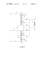
- FIG. 1 is a circuit diagram showing the charging circuit of this invention.
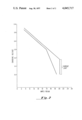
- FIG. 2 is a graph showing typical limits within which the charging characteristic for the battery charger of this invention is found.
- FIG. 1 there is shown a circuit diagram of the battery charger of this invention.
- Lines 21, 22 and 23 are connected between a three phase power line comprised of L1, L2 and L3, and the primary windings of a Scott T connected transformer 24.
- the transformer has two sections, 25 and 26, comprising two input windings, with the end of one input winding connected, at point 26M, to the center of the other input winding.
- Transformer 24 has four secondary windings, 25S and 25R, and 26S and 26R.
- Windings 25S and 26S are secondary output windings, each of which is center tapped at 25C and 26C, the two center taps being connected together.
- Diodes 40, 41, 42 and 43 are connected to respective ends of windings 25S and 26S, in a four phase star configuration.
- the cathodes of the four diodes are coupled together and connected to output terminal 46.
- the common connection of the center taps is connected to output terminal 47.
- the battery load 50 is placed between terminals 46 and 47 for charging.
- Output windings 25R and 26R ar physically positioned with respect to windings 25S and 26S respectively, to that the currents through 25R and 26R cause some saturation in transformers 25 and 26 respectively, so as to provide a degree of regulation to line voltage variation.
- Across winding 25R is placed a capacitance 28, the winding 25R and capacitance 28 forming a resonant circuit which carries a capacitive load, i.e. capacitive volt amperes.
- winding 26R and capacitor 29 form a path for capacitive volt amperes.
- These arrangements constitute a ferroresonant transformer circuit which provides the desired taper characteristic or charging characteristic for recharging the battery load 50.
- the capacitor 28 and 29 may either be integrated within the winding of the ferroresonant transformer, or mechanically integrated as part of the transformer.
- the desired magnetic conduction path through the transformer may be obtained either by conventional interleaving construction, or by the use of butt stacking.
- FIG. 2 there are shown curves representing typical limits of the charging characteristic of the battery charger of this invention.
- the curves shown are per unit curves, the Y axis representing charging volts per cell, and the X axis representing charging amperes per 100 amp hour capacity of the battery being charged.
- AH 500 amp hour
- the start rate is limited to about 20.4 amps per 100 AH
- the volts per cell has reached about 2.52 volts
- the charging current is reduced to between 4 and 5 amps per 100 AH.
- the saturation effect contributed by the ferroresonant circuit is a prime determinant of the current limiting portion of the charging characteristic.
- the efficiency and reliability of the charger of this invention is to be appreciated in comparison with a conventional three phase transformer type charging circuit.
- this circuit of this invention only two transformer sections are required, instead of three, each transformer handling about 1.5 times the KVA of the normal three phase transformer section.
- This design in allowing two transformers instead of three, makes possible a savings in the amount of labor, as well as savings in the number of diodes, since only four diodes are necessary instead of six.
- the arrangement also contributes to increased reliability, because of the reduced number of components, both transformer components and diodes.
- the charger of this invention is designed by connecting the two transformer sections in a Scott T configuration, and then selecting the capacitors for the ferroresonant circuit so that the resulting charging characteristic is within the design limits. If the selected capacitor is too large, corresponding to a given winding voltage in a ferroresonant circuit, the charging current is too high throughout the charging range. Conversely, if the capacitance of the selected capacitor is too low, the charging current is too little, such that regulation becomes a problem and the charging circuit requires much too great a time to achieve the desired charge on the battery load.
- the selection of the ferroresonant capacitors is made with an effective load 50 across terminals 46 and 47, so that capacitors 28 and 29 are chosen to cooperate with the effective capacitence of the load.
- circuit diagrammed in FIG. 1 shows simply a single arrangement for connection to a power line
- a dual voltage arrangement for connection to either a high voltage or low voltage line is also within the scope of this invention.
Landscapes
- Engineering & Computer Science (AREA)
- Power Engineering (AREA)
- Charge And Discharge Circuits For Batteries Or The Like (AREA)
Abstract
Description
Claims (2)
Priority Applications (1)
| Application Number | Priority Date | Filing Date | Title |
|---|---|---|---|
| US05/676,475 US4045717A (en) | 1975-03-17 | 1976-04-13 | Battery charger |
Applications Claiming Priority (2)
| Application Number | Priority Date | Filing Date | Title |
|---|---|---|---|
| US55915975A | 1975-03-17 | 1975-03-17 | |
| US05/676,475 US4045717A (en) | 1975-03-17 | 1976-04-13 | Battery charger |
Related Parent Applications (1)
| Application Number | Title | Priority Date | Filing Date |
|---|---|---|---|
| US55915975A Continuation | 1975-03-17 | 1975-03-17 |
Publications (1)
| Publication Number | Publication Date |
|---|---|
| US4045717A true US4045717A (en) | 1977-08-30 |
Family
ID=27071975
Family Applications (1)
| Application Number | Title | Priority Date | Filing Date |
|---|---|---|---|
| US05/676,475 Expired - Lifetime US4045717A (en) | 1975-03-17 | 1976-04-13 | Battery charger |
Country Status (1)
| Country | Link |
|---|---|
| US (1) | US4045717A (en) |
Cited By (6)
| Publication number | Priority date | Publication date | Assignee | Title |
|---|---|---|---|---|
| US4629965A (en) * | 1985-02-26 | 1986-12-16 | General Battery Corporation | Battery charger termination circuit |
| US4631471A (en) * | 1985-03-25 | 1986-12-23 | At&T Bell Laboratories | Inductor apparatus for application of ferroresonant regulators |
| US4672295A (en) * | 1985-08-01 | 1987-06-09 | Motor Appliance Corporation | Battery charger circuit |
| US7528579B2 (en) | 2003-10-23 | 2009-05-05 | Schumacher Electric Corporation | System and method for charging batteries |
| US20110215743A1 (en) * | 2010-03-08 | 2011-09-08 | Kabushiki Kaisha Toyota Jidoshokki | Battery charging circuit and charging method |
| US9343996B2 (en) | 2014-02-04 | 2016-05-17 | Pavel Dourbal | Method and system for transmitting voltage and current between a source and a load |
Citations (2)
| Publication number | Priority date | Publication date | Assignee | Title |
|---|---|---|---|---|
| US2996656A (en) * | 1959-02-02 | 1961-08-15 | Basic Products Corp | Voltage regulating apparatus |
| US3843918A (en) * | 1973-11-15 | 1974-10-22 | Gould Inc | Ferroresonant transformer battery charger circuit |
-
1976
- 1976-04-13 US US05/676,475 patent/US4045717A/en not_active Expired - Lifetime
Patent Citations (2)
| Publication number | Priority date | Publication date | Assignee | Title |
|---|---|---|---|---|
| US2996656A (en) * | 1959-02-02 | 1961-08-15 | Basic Products Corp | Voltage regulating apparatus |
| US3843918A (en) * | 1973-11-15 | 1974-10-22 | Gould Inc | Ferroresonant transformer battery charger circuit |
Cited By (8)
| Publication number | Priority date | Publication date | Assignee | Title |
|---|---|---|---|---|
| US4629965A (en) * | 1985-02-26 | 1986-12-16 | General Battery Corporation | Battery charger termination circuit |
| US4631471A (en) * | 1985-03-25 | 1986-12-23 | At&T Bell Laboratories | Inductor apparatus for application of ferroresonant regulators |
| US4672295A (en) * | 1985-08-01 | 1987-06-09 | Motor Appliance Corporation | Battery charger circuit |
| US7528579B2 (en) | 2003-10-23 | 2009-05-05 | Schumacher Electric Corporation | System and method for charging batteries |
| US7808211B2 (en) | 2003-10-23 | 2010-10-05 | Schumacher Electric Corporation | System and method for charging batteries |
| US20110215743A1 (en) * | 2010-03-08 | 2011-09-08 | Kabushiki Kaisha Toyota Jidoshokki | Battery charging circuit and charging method |
| US8421381B2 (en) * | 2010-03-08 | 2013-04-16 | Kabushiki Kaisha Toyota Jidoshokki | Battery charging circuit and charging method |
| US9343996B2 (en) | 2014-02-04 | 2016-05-17 | Pavel Dourbal | Method and system for transmitting voltage and current between a source and a load |
Similar Documents
| Publication | Publication Date | Title |
|---|---|---|
| US4296461A (en) | Battery package with DC to DC converter | |
| RU2364016C1 (en) | System and method of limiting alternating inrush current | |
| US5563778A (en) | Uninterruptible power supply system | |
| US4219872A (en) | Power supply | |
| US4045717A (en) | Battery charger | |
| US6982884B1 (en) | Autotransformers to parallel AC to DC converters | |
| US4323960A (en) | Dual mode direct current power supply | |
| US2804588A (en) | Power supply apparatus | |
| CA1080797A (en) | Battery charger with transformers in scott-t configuration | |
| US4672295A (en) | Battery charger circuit | |
| US2434493A (en) | Voltage stabilizing transformer | |
| US2341446A (en) | Device suitable for charging batteries | |
| GB1566334A (en) | Charging of batteries | |
| IE45339B1 (en) | Improvements in or relating to the charging of batteries | |
| US4584637A (en) | Multiple step-up rectifier circuit | |
| US3849701A (en) | Integrated dual voltage power supply | |
| US5510692A (en) | Ferroresonant battery charger with constant current finish rate | |
| JPS6159047B2 (en) | ||
| JPS5837717A (en) | Compensation circuit for output holding time for power supply device | |
| SU959211A1 (en) | Apparatus for charging storage batteries | |
| US4442482A (en) | Dual output H.V. rectifier power supply driven by common transformer winding | |
| RU2009808C1 (en) | Single-phase rectifier for welding, starting car engine and charging storage battery | |
| US2783431A (en) | Decoupled converter system | |
| US2281645A (en) | Voltage regulator | |
| JPS62193515A (en) | Service interruption free electric source |
Legal Events
| Date | Code | Title | Description |
|---|---|---|---|
| AS | Assignment |
Owner name: CITICORP INDUSTRIAL CREDIT, INC., 725 SOUTH FIGUER Free format text: SECURITY INTEREST;ASSIGNOR:GENERAL BATTERY CORPORATION;REEL/FRAME:004807/0225 Effective date: 19870526 |
|
| STCF | Information on status: patent grant |
Free format text: PATENTED FILE - (OLD CASE ADDED FOR FILE TRACKING PURPOSES) |
|
| AS | Assignment |
Owner name: CHEMICAL BANK, A NY BANKING CORPORATION Free format text: SECURITY INTEREST;ASSIGNORS:EXIDE CORPORATION;GENERAL BATTERY CORPORATION;ESB PUERTO RICO CORP.;AND OTHERS;REEL/FRAME:005449/0001 Effective date: 19900831 |
|
| AS | Assignment |
Owner name: YUASA-EXIDE, INC. Free format text: CHANGE OF NAME;ASSIGNOR:YUASA BATTERY (AMERICA), INC.;REEL/FRAME:005949/0153 Effective date: 19911125 |
|
| AS | Assignment |
Owner name: YERMCO, INC., DELAWARE Free format text: ASSIGNMENT OF ASSIGNORS INTEREST;ASSIGNOR:YUASA EXIDE, INC.;REEL/FRAME:007629/0001 Effective date: 19941128 |