US4046030A - Final drive unit - Google Patents
Final drive unit Download PDFInfo
- Publication number
- US4046030A US4046030A US05/674,186 US67418676A US4046030A US 4046030 A US4046030 A US 4046030A US 67418676 A US67418676 A US 67418676A US 4046030 A US4046030 A US 4046030A
- Authority
- US
- United States
- Prior art keywords
- housing
- drive
- drive shaft
- improvement
- inner tubular
- Prior art date
- Legal status (The legal status is an assumption and is not a legal conclusion. Google has not performed a legal analysis and makes no representation as to the accuracy of the status listed.)
- Expired - Lifetime
Links
Images
Classifications
-
- F—MECHANICAL ENGINEERING; LIGHTING; HEATING; WEAPONS; BLASTING
- F16—ENGINEERING ELEMENTS AND UNITS; GENERAL MEASURES FOR PRODUCING AND MAINTAINING EFFECTIVE FUNCTIONING OF MACHINES OR INSTALLATIONS; THERMAL INSULATION IN GENERAL
- F16F—SPRINGS; SHOCK-ABSORBERS; MEANS FOR DAMPING VIBRATION
- F16F15/00—Suppression of vibrations in systems; Means or arrangements for avoiding or reducing out-of-balance forces, e.g. due to motion
- F16F15/10—Suppression of vibrations in rotating systems by making use of members moving with the system
- F16F15/14—Suppression of vibrations in rotating systems by making use of members moving with the system using masses freely rotating with the system, i.e. uninvolved in transmitting driveline torque, e.g. rotative dynamic dampers
- F16F15/1407—Suppression of vibrations in rotating systems by making use of members moving with the system using masses freely rotating with the system, i.e. uninvolved in transmitting driveline torque, e.g. rotative dynamic dampers the rotation being limited with respect to the driving means
- F16F15/1414—Masses driven by elastic elements
- F16F15/1435—Elastomeric springs, i.e. made of plastic or rubber
- F16F15/1442—Elastomeric springs, i.e. made of plastic or rubber with a single mass
-
- B—PERFORMING OPERATIONS; TRANSPORTING
- B60—VEHICLES IN GENERAL
- B60K—ARRANGEMENT OR MOUNTING OF PROPULSION UNITS OR OF TRANSMISSIONS IN VEHICLES; ARRANGEMENT OR MOUNTING OF PLURAL DIVERSE PRIME-MOVERS IN VEHICLES; AUXILIARY DRIVES FOR VEHICLES; INSTRUMENTATION OR DASHBOARDS FOR VEHICLES; ARRANGEMENTS IN CONNECTION WITH COOLING, AIR INTAKE, GAS EXHAUST OR FUEL SUPPLY OF PROPULSION UNITS IN VEHICLES
- B60K17/00—Arrangement or mounting of transmissions in vehicles
- B60K17/04—Arrangement or mounting of transmissions in vehicles characterised by arrangement, location, or kind of gearing
- B60K17/16—Arrangement or mounting of transmissions in vehicles characterised by arrangement, location, or kind of gearing of differential gearing
-
- B—PERFORMING OPERATIONS; TRANSPORTING
- B60—VEHICLES IN GENERAL
- B60K—ARRANGEMENT OR MOUNTING OF PROPULSION UNITS OR OF TRANSMISSIONS IN VEHICLES; ARRANGEMENT OR MOUNTING OF PLURAL DIVERSE PRIME-MOVERS IN VEHICLES; AUXILIARY DRIVES FOR VEHICLES; INSTRUMENTATION OR DASHBOARDS FOR VEHICLES; ARRANGEMENTS IN CONNECTION WITH COOLING, AIR INTAKE, GAS EXHAUST OR FUEL SUPPLY OF PROPULSION UNITS IN VEHICLES
- B60K17/00—Arrangement or mounting of transmissions in vehicles
- B60K17/22—Arrangement or mounting of transmissions in vehicles characterised by arrangement, location, or type of main drive shafting, e.g. cardan shaft
- B60K17/24—Arrangements of mountings for shafting
-
- F—MECHANICAL ENGINEERING; LIGHTING; HEATING; WEAPONS; BLASTING
- F16—ENGINEERING ELEMENTS AND UNITS; GENERAL MEASURES FOR PRODUCING AND MAINTAINING EFFECTIVE FUNCTIONING OF MACHINES OR INSTALLATIONS; THERMAL INSULATION IN GENERAL
- F16D—COUPLINGS FOR TRANSMITTING ROTATION; CLUTCHES; BRAKES
- F16D3/00—Yielding couplings, i.e. with means permitting movement between the connected parts during the drive
- F16D3/50—Yielding couplings, i.e. with means permitting movement between the connected parts during the drive with the coupling parts connected by one or more intermediate members
- F16D3/72—Yielding couplings, i.e. with means permitting movement between the connected parts during the drive with the coupling parts connected by one or more intermediate members with axially-spaced attachments to the coupling parts
- F16D3/74—Yielding couplings, i.e. with means permitting movement between the connected parts during the drive with the coupling parts connected by one or more intermediate members with axially-spaced attachments to the coupling parts the intermediate member or members being made of rubber or other rubber-like flexible material
-
- F—MECHANICAL ENGINEERING; LIGHTING; HEATING; WEAPONS; BLASTING
- F16—ENGINEERING ELEMENTS AND UNITS; GENERAL MEASURES FOR PRODUCING AND MAINTAINING EFFECTIVE FUNCTIONING OF MACHINES OR INSTALLATIONS; THERMAL INSULATION IN GENERAL
- F16F—SPRINGS; SHOCK-ABSORBERS; MEANS FOR DAMPING VIBRATION
- F16F15/00—Suppression of vibrations in systems; Means or arrangements for avoiding or reducing out-of-balance forces, e.g. due to motion
- F16F15/10—Suppression of vibrations in rotating systems by making use of members moving with the system
- F16F15/12—Suppression of vibrations in rotating systems by making use of members moving with the system using elastic members or friction-damping members, e.g. between a rotating shaft and a gyratory mass mounted thereon
- F16F15/121—Suppression of vibrations in rotating systems by making use of members moving with the system using elastic members or friction-damping members, e.g. between a rotating shaft and a gyratory mass mounted thereon using springs as elastic members, e.g. metallic springs
- F16F15/124—Elastomeric springs
- F16F15/126—Elastomeric springs consisting of at least one annular element surrounding the axis of rotation
-
- F—MECHANICAL ENGINEERING; LIGHTING; HEATING; WEAPONS; BLASTING
- F16—ENGINEERING ELEMENTS AND UNITS; GENERAL MEASURES FOR PRODUCING AND MAINTAINING EFFECTIVE FUNCTIONING OF MACHINES OR INSTALLATIONS; THERMAL INSULATION IN GENERAL
- F16H—GEARING
- F16H48/00—Differential gearings
- F16H48/06—Differential gearings with gears having orbital motion
- F16H48/08—Differential gearings with gears having orbital motion comprising bevel gears
-
- F—MECHANICAL ENGINEERING; LIGHTING; HEATING; WEAPONS; BLASTING
- F16—ENGINEERING ELEMENTS AND UNITS; GENERAL MEASURES FOR PRODUCING AND MAINTAINING EFFECTIVE FUNCTIONING OF MACHINES OR INSTALLATIONS; THERMAL INSULATION IN GENERAL
- F16C—SHAFTS; FLEXIBLE SHAFTS; ELEMENTS OR CRANKSHAFT MECHANISMS; ROTARY BODIES OTHER THAN GEARING ELEMENTS; BEARINGS
- F16C2326/00—Articles relating to transporting
- F16C2326/01—Parts of vehicles in general
- F16C2326/06—Drive shafts
-
- F—MECHANICAL ENGINEERING; LIGHTING; HEATING; WEAPONS; BLASTING
- F16—ENGINEERING ELEMENTS AND UNITS; GENERAL MEASURES FOR PRODUCING AND MAINTAINING EFFECTIVE FUNCTIONING OF MACHINES OR INSTALLATIONS; THERMAL INSULATION IN GENERAL
- F16C—SHAFTS; FLEXIBLE SHAFTS; ELEMENTS OR CRANKSHAFT MECHANISMS; ROTARY BODIES OTHER THAN GEARING ELEMENTS; BEARINGS
- F16C27/00—Elastic or yielding bearings or bearing supports, for exclusively rotary movement
- F16C27/06—Elastic or yielding bearings or bearing supports, for exclusively rotary movement by means of parts of rubber or like materials
- F16C27/066—Ball or roller bearings
-
- F—MECHANICAL ENGINEERING; LIGHTING; HEATING; WEAPONS; BLASTING
- F16—ENGINEERING ELEMENTS AND UNITS; GENERAL MEASURES FOR PRODUCING AND MAINTAINING EFFECTIVE FUNCTIONING OF MACHINES OR INSTALLATIONS; THERMAL INSULATION IN GENERAL
- F16C—SHAFTS; FLEXIBLE SHAFTS; ELEMENTS OR CRANKSHAFT MECHANISMS; ROTARY BODIES OTHER THAN GEARING ELEMENTS; BEARINGS
- F16C3/00—Shafts; Axles; Cranks; Eccentrics
- F16C3/02—Shafts; Axles
-
- F—MECHANICAL ENGINEERING; LIGHTING; HEATING; WEAPONS; BLASTING
- F16—ENGINEERING ELEMENTS AND UNITS; GENERAL MEASURES FOR PRODUCING AND MAINTAINING EFFECTIVE FUNCTIONING OF MACHINES OR INSTALLATIONS; THERMAL INSULATION IN GENERAL
- F16H—GEARING
- F16H48/00—Differential gearings
- F16H48/38—Constructional details
- F16H48/42—Constructional details characterised by features of the input shafts, e.g. mounting of drive gears thereon
- F16H2048/423—Constructional details characterised by features of the input shafts, e.g. mounting of drive gears thereon characterised by bearing arrangement
-
- F—MECHANICAL ENGINEERING; LIGHTING; HEATING; WEAPONS; BLASTING
- F16—ENGINEERING ELEMENTS AND UNITS; GENERAL MEASURES FOR PRODUCING AND MAINTAINING EFFECTIVE FUNCTIONING OF MACHINES OR INSTALLATIONS; THERMAL INSULATION IN GENERAL
- F16H—GEARING
- F16H48/00—Differential gearings
- F16H48/38—Constructional details
- F16H48/42—Constructional details characterised by features of the input shafts, e.g. mounting of drive gears thereon
Abstract
Driving torque from the propeller shaft is transmitted to the drive pinion which is in constant mesh with the ring gear of the differential assembly while torsional vibration in the drive line is absorbed by the coupler provided in the pinion drive shaft.
Description
The present invention relates to the motor vehicle drive line, and more particularly to the improvement of the final drive unit of the drive line.
The motor vehicle drive line is generally made up of a propeller shaft, final drive unit including a differential mechanism and axles for the vehicle driving wheels and, in effect, transmits engine power from the transmission therethrough. The differential mechanism is effective in distributing engine power to the respective driving wheels to drive the driving wheels via a selected reduction ratio.
During operation of the motor vehicle, especially acceleration and deceleration conditions, torsional stresses occur in the drive line owing to the variation of the driving torque. Such stresses induce in the drive line torsional vibrations and accompanying lateral vibrations.
Such torsional and lateral vibrations have a detrimental effect on the efficiency as well as the life of many of the components of both the propeller shaft and the final drive unit. More particularly, such torsional and lateral vibrations are largely responsible for power losses between the engine and final drive unit, objectionable noise in the operation of the propeller shaft and the final drive unit, and excessive wear of the perishable components of the drive line.
In a majority of drive lines, the propeller shaft is apt to be of considerable length relative to its diameter since the engine is generally mounted at the front side of the vehicle and on the other hand the final drive unit is positioned at the rear end of the motor vehicle. Therefore, the above-mentioned vibrations become intense in such propeller shaft because the critical speed of such propeller shaft is considerably lower than the critical speeds of other components in the drive line and further because the vibration amplitude of a propeller shaft of a given diameter increases as the length increases.
To elevate the critical speed of a propeller shaft there has been proposed a technique to lengthen the pinion drive shaft of the final drive unit thereby shortening the propeller shaft by the length as long as the increased length of the pinion drive shaft.
Such a technique is advantageous for increasing the rigidity of the propeller shaft itself against the lateral force, and therefore to some extent advantageous for reducing the forgoing detrimental effect and drawbacks. However, such a technique does not make provision for eliminating or reducing torsional vibrations resulting from the torsional stresses in the drive line, therefore such technique cannot satisfactorily overcome the forgoing disadvantages in the drive line.
It is therefore a general object of the present invention to provide a vehicle drive line including an improved final drive unit which can effectively eliminate torsinal vibrations of the drive line or reduce them to some extent of negligible quantity.
It is a more specific object of the present invention to provide a coupling device which can effectively absorb torsional vibrations and which is simple and compact in construction.
It is still another object of the present invention to provide a torsional vibration damping coupler device which has provision for rigidly connecting the driving shaft to the driven shaft when the drive torque exceeds a predetermined value.
Other objects and features of the final drive unit incoperating the improvement according to the present invention will become more apparent from the following description taken in conjunction with the accompanying drawings in which:
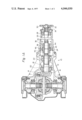
FIG. 1A is a sectional view of the final drive unit according to the present invention incorporating an improved pinion drive shaft and a vibration damping coupler;
FIG. 1B is an enlarged sectional view of a vibration damping coupler taken on line A--A of FIG. 1A;
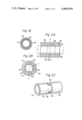
FIG. 2A is a sectional view showing another embodiment of a vibration damping coupler taken on line Y--Y of FIG. 2B;
FIG. 2B is a sectional view showing another embodiment of a vibration damping coupler taken on line X--X of FIG. 2A;
FIG. 2C is a schematic perspective view of another embodiment of a vibration damping coupler similar to those shown in FIGS. 2A and 2B, but with some parts are omitted.
Reference will now be made to the drawings, first to FIG. 1A. The reference numeral 10 illustrates a final drive unit in a drive line in a motor vehicle. The final drive unit 10 includes a carrier housing 12 which is supported by the vehicle suspension system (not shown) or fastened to the vehicle body. The carrier housing 12 carries therein a differential ring gear 14 which is in constant mesh with a drive pinion 16. A first differential pinion drive shaft 18 (which will hereinafter be referred to as a first drive shaft) of the drive pinion 16, extending fore-and-aft direction of the vehicle body, is journaled in the carrier housing 12 through front and rear pinion bearings 20 and 22 which are shown as being tapered roller bearings. The first drive shaft 18 carries at its rear end the drive pinion 16 which is in constant mesh with the differential ring gear 14 and at its front end is provided with splines on the exterior surface thereof. The carrier housing 12 is jointed to an extension housing 24, extending in the fore-and-aft direction of the vehicle body, in which a second differential pinion drive shaft 26 (which will hereinafter be referred to as a second drive shaft) is journaled through a bearing 28 located at the front end of the extension housing 24 and arranged so as to be substantially in axial alignment with the first drive shaft 18. The second drive shaft 26 has a front end portion splined to the internally splined opening of a pinion drive flange 30 which is secured around the second drive shaft 26 by means of a pinion drive flange nut 32 through a locker washer 34 and a rear end portion provided with splines. A vibration damping coupler 36 is provided about the first and second drive shafts 18 and 26 for resilient connection therebetween. The vibration damping coupler 36, as shown in FIG. 1A and 1B, comprises an outer tubular housing 38 preferably formed of metal, and inner tubular housings 40 and 42 concentrically arranged with respect to the outer tubular housing 38 and axially spaced from each other and preferably formed of metal. Each of the inner tubular housings 40 and 42 has a substantially cylindrical inner surface provided with splines and an outer surface circumferentially spaced from the inner surface of the outer tubular housing 38 to provide therebetween a chamber having an annular cross-section for accommodating a body of yieldable resilient material 44 such, for example, as rubber or a substance having characteristics similar to rubber. The body of resilient material 44 is bonded both to the inner surface of the outer tubular housing 38 and to the outer surfaces of the inner tubular housings 40 and 42 by either a chemical bond or a frictional bond, or by a combination of the two bonds. The inner tubular housings 40 and 42 are respectively splined to the front end portion of the first drive shaft 18 and the rear end portion of the second drive shaft 26, and the outer tubular housing 38 is rotatably supported in the extension housing 24 through a bearing 46 which is shown as a ball bearing. The body of resilient material 44, as clearly shown, preferably comprises on the inner surface thereof a radially inwardly extruding portion 45 to separate the first and second drive shafts 18 and 26 in the axial direction. With this arrangement, driving torque is transmitted from the propeller shaft through a rear universal joint and the pinion drive flange 30 to the second drive shaft 26 which in turn transmits the driving torque to the first drive shaft 18 by way of the inner tubular housing 42, the body of resilient material 44 and the inner tubular housing 40. During driving torque transmission through the body of resilient material 44, torsional vibrations created by any of the shafts in the drive line including the propeller shaft are advantageously absorbed by the body of resilient material 44 instead of being transmitted to the other shaft in either direction rotation of the propeller shaft. Furthermore, since the torsional damping coupler 36 is advantageously supported by the bearing 46 which in turn carried by the extension housing 24, it advantageously elevates the lateral vibration resonance frequency of the coupled first and second drive shaft.
FIGS. 2A, 2B and 2C illustrate another embodiment of a torsional damping coupler 50 according to the present invention. The torsional damping coupler 50 of this embodiment includes an outer tubular housing 52, inner tubular housings 54 and 55, and a body of resilient material 56, which are respectively arranged into a construction substantially similar to the coupler shown in FIGS. 1A and 1B. The body of resilient material 56 resiliently interconnects the outer surfaces of the inner tubular housings 54 and 55 and the inner surface of the outer tubular housing 52 and is bonded thereto in the same manner as was reviously mentioned with respect to FIGS. 1A and 1B. As shown in FIGS. 2A and 2C (FIG. 2C omits the outer tubular housing 52 and the body of resilient material 56 for clear illustration of the arrangement of the inner tubular housings 54 and 55), the inner tubular housings 54 and 55 are respectively provided with axially extending end portions or projections 58 and 60. The projections 58 and 60 are so disposed that the projections 58 respectively extend between the projections 60 and are also concentrically arranged with respect to the outer tubular housing 52. As is shown in FIG. 2B, the arcuate extent of the projections 58 and 60 is predetermined to provide the desired circumferential space 62 between the adjacent sides of the projections. As is shown in FIG. 2A, the inner tubular housings 54 and 55 are respectively provided with internally splined inner surfaces to which the first and second drive shafts are splined.
With this arrangement, the driving torque is transmitted from the propeller shaft through a rear universal joint and the second drive shaft which in turn transmits the driving torque to the torsional vibration damping coupler 50 according to the present invention. The torsional vibration damping coupler 50 transmits the driving torque from the second drive shaft 26 to the first drive shaft 18 through the inner tubular housing 55 splined to the rear end of the second drive shaft 26, the body of resilient material 56 and the inner tubular housing 54 splined to the front end of the first drive shaft 18. The torsional vibrations created by any of the shafts in the drive line are advantageously absorbed by the body of resilient material 56 in the same manner as was mentioned with respect to FIGS. 1A and 1B. As the driving torque transmitted through the drive line increases, the circumferential space 62 decreases as the result of increase of the relative circumferential displacement between the inner tubular housings 54 and 55. When the driving torque transmitted through the drive line exceeds a predetermined value, the circumferentially overlying portions or projections 58 and 60 abut onto each other. The driving torque, at this moment, is transmitted directly from the second drive shaft 26 to the first drive shaft 18 through the projections 58 and 60 of the inner tubular housings 54 and 55 which are respectively splined to the first and second drive shafts 18 and 26. Such a severe compression of the resilient material 56 may temporarily deprive the coupler of the capacity to absorb torsional vibrations in the drive line. However, since such exceedingly large driving torque occurs in the drive line only when the drive line is rotating at lower speeds relative to the available maximum high speed of the drive line, stresses caused by such drive torque do not induce any of the shafts in the drive line to set up torsional vibrations which may cause any harm to the drive line.
From the forgoing description, it will have been understood that according to the present invention the one-piece pinion drive shaft is separated into two pieces of pinion drive shafts to be coupled by a torsional vibration damping coupler whereby the torsional vibrations occuring in the drive line are eliminated or at least reduced to a negligible quantity.
In addition, since the torsional damping coupler is supported by the bearing which is in turn carried by the extension housing, it advantageously elevates lateral vibration the resonance frequency of the coupled two-piece pinion drive shaft.
Furthermore, according to the present invention, it is provided a torsional vibration damping coupler having a rather simple construction, which has the advantages of cheapness and long life besides the ability to effectively absorb torsional vibrations occuring in the drive line.
In addition, the torsional vibration damping coupler according to the present invention preferably includes a provision for positively mechanically connecting the two-piece pinion drive shaft when the drive torque exceeds a predetermined amount.
While only two embodiments of the final drive unit of the present invention have thus far been described and shown, such are merely by way of example and, thus, numerous changes and modifications may be incoperated into such embodiments.
Claims (8)
1. In a final drive unit of a motor vehicle line, the improvement comprising, in combination, first and second drive shafts substantially in axial alignment with each other and rotatably supported by bearings in a housing, said first drive shaft having a first end portion integrally connected with a drive pinion which is in constant mesh with a ring gear and a second end portion, said second drive shaft having a first end portion interlockingly connected with a pinion drive flange which is rotatably driven by a rear universal joint and a second end portion, a vibration damping coupler for resiliently coupling the second end portion of said first drive shaft with the second end portion of said second drive shaft, and bearing means rotatably supporting said vibration damping coupler in said housing.
2. The improvement as claimed in claim 1, in which said bearing means comprises at least one bearing in said housing rotatably supporting said vibration damping coupler in said housing.
3. The improvement as claimed in claim 1, in which said vibration damping coupler comprises an outer tubular housings, a pair of inner tubular housing each concentrically arranged with respect to said outer tubular housing and axially spaced from each other, each of said inner tubular housings being respectively connected to said first and second drive shafts, and a body or resilient material resiliently interconnecting between the outer surfaces of said inner tubular housings and the inner surface of said outer tubular housing.
4. The improvement as claimed in claim 3, wherein each of said first and second drive shafts respectively comprises splines on the second end portion thereof, and each of said inner tubular housings respectively comprises splines on the inner surface thereof.
5. The improvement as claimed in claim 3, in which said body of resilient material comprises on the inner surface thereof a radially inwardly extending flange separating said first and second drive shafts from each other in the axial direction.
6. The improvement as claimed in claim 3, in which a pair of said inner tubular housings respectively have axially extending end portions which circumferentially overlie and are spaced from each other to abut onto each other when the relative circumferential displacement between said inner tubular housings is above a certain value.
7. The improvement as claimed in claim 1 wherein said pair of inner tubular members are axially spaced from one another, said body of resilient material having a radially inwardly extending portion extending into the space between said inner tubular members, said first and second drive shafts having their respective second end portions axially spaced from one another, said radially inwardly extending portion of said body of resilient material extending into the space between said first and second drive shaft.
8. The improvement as claimed in claim 1 wherein said housing comprises a carrier housing and an extension housing mounted on the carrier housing, first bearing means rotatably supporting said first drive shaft in said carrier housing, second bearing means rotatably supporting said second drive shaft in said extension housing, and third bearing means rotatably supporting said vibration damping coupler in said extension housing.
Applications Claiming Priority (2)
| Application Number | Priority Date | Filing Date | Title |
|---|---|---|---|
| JP1975046991U JPS51126515U (en) | 1975-04-09 | 1975-04-09 | |
| JA50-46991 | 1975-04-09 |
Publications (1)
| Publication Number | Publication Date |
|---|---|
| US4046030A true US4046030A (en) | 1977-09-06 |
Family
ID=12762655
Family Applications (1)
| Application Number | Title | Priority Date | Filing Date |
|---|---|---|---|
| US05/674,186 Expired - Lifetime US4046030A (en) | 1975-04-09 | 1976-04-06 | Final drive unit |
Country Status (5)
| Country | Link |
|---|---|
| US (1) | US4046030A (en) |
| JP (1) | JPS51126515U (en) |
| DE (1) | DE2615707A1 (en) |
| FR (1) | FR2307194A1 (en) |
| GB (1) | GB1522734A (en) |
Cited By (13)
| Publication number | Priority date | Publication date | Assignee | Title |
|---|---|---|---|---|
| US4277957A (en) * | 1978-09-29 | 1981-07-14 | Lucas Industries Limited | Spline drive arrangements |
| US4597311A (en) * | 1982-03-23 | 1986-07-01 | Toyota Jidosha Kabushiki Kaisha | Final speed-reduction gearing assembly in transmission unit |
| US4649774A (en) * | 1983-10-04 | 1987-03-17 | Norbar Torque Tools Ltd. | Reversible torque converter |
| US4699017A (en) * | 1984-10-10 | 1987-10-13 | Compagnie Industrielle De Mecanismes En Abrege C.I.M. | Electric motor-speed reducer unit for driving accessories of motor vehicles, such as window glasses |
| US4721011A (en) * | 1985-09-04 | 1988-01-26 | Toyota Jidosha Kabushiki Kaisha | Four wheel drive power transmission system with front propeller shaft including no universal joints connecting transfer device to front differential |
| US4726254A (en) * | 1985-09-04 | 1988-02-23 | Toyota Jidosha Kabushiki Kaisha | Four wheel drive power transmission system with front universal joint of front propeller shaft located towards gearbox from engine |
| US4907470A (en) * | 1989-08-02 | 1990-03-13 | Deere & Company | Differential housing support |
| US5094542A (en) * | 1990-11-19 | 1992-03-10 | General Signal Corporation | Modular mixer system |
| US20080296078A1 (en) * | 2007-05-30 | 2008-12-04 | American Axle & Manufacturing, Inc. | Torque transfer device with torque tube coupling mechanism |
| US20090258749A1 (en) * | 2008-04-14 | 2009-10-15 | Toyota Jidosha Kabushiki Kaisha | Vibration damping device and power transmission device |
| CN107327538A (en) * | 2015-12-10 | 2017-11-07 | 通用汽车环球科技运作有限责任公司 | Torsional vibration damper for vehicle |
| US10274069B2 (en) | 2016-05-02 | 2019-04-30 | Dana Heavy Vehicle Systems Group, Llc | Slip in axle assembly for a tandem axle assembly |
| CN112166267A (en) * | 2018-05-16 | 2021-01-01 | 舍弗勒技术股份两合公司 | Drive train with centrifugal pendulum |
Families Citing this family (7)
| Publication number | Priority date | Publication date | Assignee | Title |
|---|---|---|---|---|
| JPS5942502Y2 (en) * | 1978-12-11 | 1984-12-12 | 日産自動車株式会社 | universal joint |
| FR2597803B1 (en) * | 1986-04-25 | 1991-02-15 | Glaenzer Spicer Sa | TRANSMISSION DEVICE FOR FRONT DRIVE VEHICLE |
| DE3941107A1 (en) * | 1989-12-13 | 1991-06-20 | Bayerische Motoren Werke Ag | Vehicle transmission connection between drive and pinion - with provision for axial displacement to compensate length changes |
| FR2731182B1 (en) * | 1995-03-03 | 1997-04-11 | Renault Vehicules Ind | ROAD VEHICLE MOTOR BRIDGE |
| DE29716049U1 (en) * | 1997-09-08 | 1997-12-04 | Deschler Gerhard Dipl Ing | Drive unit, especially for water vehicles such as yachts, smaller passenger ships, etc. |
| JP2009540226A (en) * | 2006-06-09 | 2009-11-19 | エスゲーエフ ジュートドイッチェ ゲレンクシャイベンファブリーク ゲーエムベーハー ウント コムパニー カーゲー | Torque transmission device for attenuating vibration and transmitting torque via at least one shaft |
| KR101335469B1 (en) * | 2011-12-23 | 2013-11-29 | 한국생산기술연구원 | Drive module for differential of electric vehicle |
Citations (6)
| Publication number | Priority date | Publication date | Assignee | Title |
|---|---|---|---|---|
| US2098703A (en) * | 1937-05-28 | 1937-11-09 | Gen Motors Corp | Universal joint |
| US2952143A (en) * | 1958-12-01 | 1960-09-13 | Us Rubber Co | Flexible shaft couplings |
| US3062023A (en) * | 1961-03-08 | 1962-11-06 | Scott A Stolworthy | Compensating torque shaft assembly |
| US3252301A (en) * | 1964-04-28 | 1966-05-24 | Gen Motors Corp | Resilient shaft coupling |
| US3485062A (en) * | 1968-02-26 | 1969-12-23 | Michael P Blake | Flexible coupling |
| US3901102A (en) * | 1973-10-05 | 1975-08-26 | Gen Motors Corp | Axle retaining differential mechanism |
-
1975
- 1975-04-09 JP JP1975046991U patent/JPS51126515U/ja active Pending
-
1976
- 1976-04-06 US US05/674,186 patent/US4046030A/en not_active Expired - Lifetime
- 1976-04-09 FR FR7610399A patent/FR2307194A1/en active Granted
- 1976-04-09 DE DE19762615707 patent/DE2615707A1/en not_active Withdrawn
- 1976-04-09 GB GB14514/76A patent/GB1522734A/en not_active Expired
Patent Citations (6)
| Publication number | Priority date | Publication date | Assignee | Title |
|---|---|---|---|---|
| US2098703A (en) * | 1937-05-28 | 1937-11-09 | Gen Motors Corp | Universal joint |
| US2952143A (en) * | 1958-12-01 | 1960-09-13 | Us Rubber Co | Flexible shaft couplings |
| US3062023A (en) * | 1961-03-08 | 1962-11-06 | Scott A Stolworthy | Compensating torque shaft assembly |
| US3252301A (en) * | 1964-04-28 | 1966-05-24 | Gen Motors Corp | Resilient shaft coupling |
| US3485062A (en) * | 1968-02-26 | 1969-12-23 | Michael P Blake | Flexible coupling |
| US3901102A (en) * | 1973-10-05 | 1975-08-26 | Gen Motors Corp | Axle retaining differential mechanism |
Cited By (17)
| Publication number | Priority date | Publication date | Assignee | Title |
|---|---|---|---|---|
| US4277957A (en) * | 1978-09-29 | 1981-07-14 | Lucas Industries Limited | Spline drive arrangements |
| US4597311A (en) * | 1982-03-23 | 1986-07-01 | Toyota Jidosha Kabushiki Kaisha | Final speed-reduction gearing assembly in transmission unit |
| US4649774A (en) * | 1983-10-04 | 1987-03-17 | Norbar Torque Tools Ltd. | Reversible torque converter |
| US4699017A (en) * | 1984-10-10 | 1987-10-13 | Compagnie Industrielle De Mecanismes En Abrege C.I.M. | Electric motor-speed reducer unit for driving accessories of motor vehicles, such as window glasses |
| US4721011A (en) * | 1985-09-04 | 1988-01-26 | Toyota Jidosha Kabushiki Kaisha | Four wheel drive power transmission system with front propeller shaft including no universal joints connecting transfer device to front differential |
| US4726254A (en) * | 1985-09-04 | 1988-02-23 | Toyota Jidosha Kabushiki Kaisha | Four wheel drive power transmission system with front universal joint of front propeller shaft located towards gearbox from engine |
| US4907470A (en) * | 1989-08-02 | 1990-03-13 | Deere & Company | Differential housing support |
| US5094542A (en) * | 1990-11-19 | 1992-03-10 | General Signal Corporation | Modular mixer system |
| US20080296078A1 (en) * | 2007-05-30 | 2008-12-04 | American Axle & Manufacturing, Inc. | Torque transfer device with torque tube coupling mechanism |
| US20090258749A1 (en) * | 2008-04-14 | 2009-10-15 | Toyota Jidosha Kabushiki Kaisha | Vibration damping device and power transmission device |
| US20110245011A1 (en) * | 2008-04-14 | 2011-10-06 | Toyota Jidosha Kabushiki Kaisha | Vibration damping device and power transmission device |
| US8776636B2 (en) * | 2008-04-14 | 2014-07-15 | Toyota Jidosha Kabushiki Kaisha | Vibration damping device and power transmission device |
| CN107327538A (en) * | 2015-12-10 | 2017-11-07 | 通用汽车环球科技运作有限责任公司 | Torsional vibration damper for vehicle |
| CN107327538B (en) * | 2015-12-10 | 2019-09-03 | 通用汽车环球科技运作有限责任公司 | Torsional vibration damper for vehicle |
| US10274069B2 (en) | 2016-05-02 | 2019-04-30 | Dana Heavy Vehicle Systems Group, Llc | Slip in axle assembly for a tandem axle assembly |
| CN112166267A (en) * | 2018-05-16 | 2021-01-01 | 舍弗勒技术股份两合公司 | Drive train with centrifugal pendulum |
| US11815154B2 (en) | 2018-05-16 | 2023-11-14 | Schaeffler Technologies AG & Co. KG | Drive train having centrifugal pendulum |
Also Published As
| Publication number | Publication date |
|---|---|
| FR2307194B1 (en) | 1980-05-09 |
| JPS51126515U (en) | 1976-10-13 |
| GB1522734A (en) | 1978-08-31 |
| FR2307194A1 (en) | 1976-11-05 |
| DE2615707A1 (en) | 1976-10-21 |
Similar Documents
| Publication | Publication Date | Title |
|---|---|---|
| US4046030A (en) | Final drive unit | |
| US4836051A (en) | Differential transmission device in particular for a motor vehicle | |
| US2691283A (en) | Propeller shaft assembly and coupling structure | |
| US3848694A (en) | Torsional damper for motor vehicle drive train | |
| US3292389A (en) | Vibration-damped drive shaft | |
| JPH0274401A (en) | Full floating type axle assembly for car | |
| US2450279A (en) | Resilient shaft hanger | |
| US4829849A (en) | Power transmission system for vehicles | |
| US2394405A (en) | Two stage propeller shaft | |
| US4575310A (en) | Propeller shock absorber for marine propulsion device | |
| CN109952452B (en) | Damper on constant-speed joint pipe seat | |
| JP4405755B2 (en) | Central bearing tuned absorber | |
| US2195647A (en) | Motor vehicle | |
| US2895315A (en) | Vibration damping means | |
| US4799402A (en) | Transmission device for a front wheel drive vehicle | |
| EP0032370A2 (en) | An improved drive shaft for a vehicle or the like | |
| JPS6318525B2 (en) | ||
| US5628688A (en) | Slip yoke assembly for vehicle driveshaft | |
| US2930660A (en) | Propeller shaft and center bearing, and mounting therefor | |
| JP2537036B2 (en) | Final reducer device for vehicles equipped with automatic transmission | |
| US2311143A (en) | Torque tube drive | |
| JPH0849758A (en) | Gearing for terminal reduction gear | |
| US5944136A (en) | Transfer shaft for an automatic transmission | |
| US2904974A (en) | Propeller shaft assembly | |
| JP7456243B2 (en) | power transmission device |