US4095230A - High accuracy broadband antenna system - Google Patents
High accuracy broadband antenna system Download PDFInfo
- Publication number
- US4095230A US4095230A US05/803,710 US80371077A US4095230A US 4095230 A US4095230 A US 4095230A US 80371077 A US80371077 A US 80371077A US 4095230 A US4095230 A US 4095230A
- Authority
- US
- United States
- Prior art keywords
- spiral arms
- substrate
- spiral
- antenna
- reflector dish
- Prior art date
- Legal status (The legal status is an assumption and is not a legal conclusion. Google has not performed a legal analysis and makes no representation as to the accuracy of the status listed.)
- Expired - Lifetime
Links
Images


Classifications
-
- H—ELECTRICITY
- H01—ELECTRIC ELEMENTS
- H01Q—ANTENNAS, i.e. RADIO AERIALS
- H01Q25/00—Antennas or antenna systems providing at least two radiating patterns
- H01Q25/02—Antennas or antenna systems providing at least two radiating patterns providing sum and difference patterns
-
- H—ELECTRICITY
- H01—ELECTRIC ELEMENTS
- H01Q—ANTENNAS, i.e. RADIO AERIALS
- H01Q25/00—Antennas or antenna systems providing at least two radiating patterns
- H01Q25/002—Antennas or antenna systems providing at least two radiating patterns providing at least two patterns of different beamwidth; Variable beamwidth antennas
-
- H—ELECTRICITY
- H01—ELECTRIC ELEMENTS
- H01Q—ANTENNAS, i.e. RADIO AERIALS
- H01Q9/00—Electrically-short antennas having dimensions not more than twice the operating wavelength and consisting of conductive active radiating elements
- H01Q9/04—Resonant antennas
- H01Q9/16—Resonant antennas with feed intermediate between the extremities of the antenna, e.g. centre-fed dipole
- H01Q9/26—Resonant antennas with feed intermediate between the extremities of the antenna, e.g. centre-fed dipole with folded element or elements, the folded parts being spaced apart a small fraction of operating wavelength
- H01Q9/27—Spiral antennas
Definitions
- the present invention generally pertains to antenna systems and is particularly directed to antenna systems for use in missile guidance systems.
- An antenna system which is used for tracking targets is included in a guidance system of a missile which is intended to seek out and destroy electromagnetic radiation sources, such as enemy search and guidance control radar systems.
- electromagnetic radiation sources such as enemy search and guidance control radar systems.
- future generation antiradiation missiles must be equipped with more highly accurate seeker antenna systems for tracking target radiation sources. This implies a need for a significant reduction (by approximately an order of magnitude) in the boresight error of the antenna system and also a significant reduction in the radome error slope.
- a seeker antenna system is positioned within the radome at the nose of the missile.
- the seeker antenna system is used to detect a radiation source, whereupon the guidance system responds to such detection by causing the missile to home in on the radiation source.
- the seeker antenna system is a planar multi-arm spiral antenna which is gimballed for movement throughout a conical angle within the radome.
- the radiation field covered by the antenna is ahead of the missile and centered about the boresight axis of the missile.
- the angular deviation of the electrical boresight of an antenna from its reference boresight is known as boresight error.
- a significant factor contributing to boresight error is the presence of the radome, since wavefronts passing through the radome to the antenna are somewhat distorted.
- the radome error slope is the variation in boresight error as a function of the look angle of the antenna through the radome.
- the antenna system of the present invention provides the higher degree of accuracy desired for a broadband seeker antenna system to be used in a future generation antiradiation missile.
- the antenna system of the present invention includes a parabolic reflector dish having a dielectric substrate and a conductive material coating on the substrate; an antenna feed positioned at the focus of the paraboloid and directed at the reflector dish for providing a narrow beam radiation pattern; and a circuit for coupling energy to and/or from the antenna feed; and is characterized by the conductive material coating on the reflector substrate defining a plurality of conductive spiral arms for providing a wide beam radiation pattern; and by structure defining a cavity for backing the conductive spiral arms on the reflector substrate.
- the seeker antenna is operable in one mode as a spiral antenna, providing a wide beam radiation pattern; and functions in another mode as a parabolic reflector in combination with the antenna feed so as to provide a narrow beam radiation pattern.
- the present invention is a dual mode antenna system wherein the wide beam radiation pattern may be used for initial target acquisition by a missile guidance system and the narrow beam radiation pattern may be used for high accuracy target tracking.
- the narrow beam provided by the large aperture parabolic reflector antenna With the narrow beam provided by the large aperture parabolic reflector antenna, boresight errors and radome error slopes are significantly reduced, since the wavefront distortion due to the presence of the radome is averaged over a much larger baseleg than with a planar spiral antenna, such as is used in present generation missile guidance systems. Also, the narrow beam pattern provides increased antenna angle gain sensitivity which, in turn, reduces the boresight error magnitude in comparison with current state-of-the-art missile guidance antenna systems.
- the broad beam pattern and narrow beam pattern are provided by a single dual mode antenna system that inherently provides both patterns about a single axis, boresight deviations between the two antenna systems are minimized.
- the dual mode antenna system of the present invention provides for increased bandwidth operation at both the high and low ends of currently used multi-octave frequency bands.
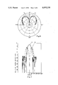
- FIG. 1 illustrates the nose portion of a missile, with a portion of the wall cut away to show the dual mode antenna system of the present invention installed in the missile.
- FIG. 2 is a perspective view of a preferred embodiment of the dual mode antenna system of the present invention.
- FIG. 3 is an enlarged sectional view of a portion of the preferred embodiment of FIG. 2 taken on line 3--3 of FIG. 1.
- FIG. 4 is an enlarged sectional view of a portion of the preferred embodiment of FIG. 2 taken on line 4--4 of FIG. 1.
- FIG. 5 is a top plan view of the preferred embodiment of FIG. 2 with portions cut away.
- FIG. 6 is a typical wide beam radiation pattern for the antenna system of FIG. 2, plotted in polar coordinates, with the amplitude in dB.
- FIG. 7 is a typical narrow beam radiation pattern for the antenna system of FIG. 2, plotted in rectangular coordinates, with the amplitude in dB.
- FIG. 8 is a plan view of an alternative preferred embodiment of the parabolic reflector dish.
- FIG. 9 is a sectional view taken on line 9--9 of FIG. 8.
- FIG. 10 is a view of a portion of a spiral arm pattern for illustrating how the circumferential arm width of a spiral arm is measured.
- the antenna system 10 is shown in FIG. 1 as being supported for movement on a gimballing system 12 within the nose portion of a missile 14.
- the antenna system 10 is positioned within a radome 16, and gimballed for movement throughout a conical angle within the radome 16.
- the radiation field covered by the antenna system 10 is ahead of the missile 14 and centered about the boresight axis of the missile 14.
- the antenna system 10 includes a circular, parabolic reflector dish 20, and an antenna feed 22 which is positioned at the focus of the paraboloid.
- the paraboloid reflector dish 20 includes a dielectric substrate 24.
- a conductive material coating on the substrate 24 defines a plurality of conductive spiral arms 25, 26, 27 and 28. It has been determined from the standpoint of ease of design and performance that the preferred number of spiral arms is four.
- the spiral arms 25, 26, 27 and 28 are displaced 90° with respect to each other.
- spiral arms 25, 27, 28 define logarithmic spirals. Preferably all four spiral arms 25, 26, 27, 28 are on the same side of the substrate 24. In order to provide optimum relfectance, the circumferential arm width of each spiral arm 25, 26, 27, 28 varies from approximately 30° near the center of the spiral to approximately 87° at the outer edge of the spiral.
- the circumferential arm width is the angle of an arc from the leading edge of the spiral arm to the trailing edge of a spiral arm that is defined by a circle intersecting with such edges and having a center in common with the spiral. Measurement of circumferential arm width is illustrated in FIG. 10. The measurement is taken along the arc 30 between the leading edge 31 and the trailing edge 32 of the spiral arm 34 that is defined by a circle having a center 35 in common with that of the spiral arm 34.
- the parabolic reflector dish 20 is backed by a cavity 37 to assure that radiation from the parabolic reflector dish 20 is substantially in only the forward direction.
- the cavity 37 is defined by an aluminum shroud 39 and an aluminum mating plate 40.
- the cavity 37 is loaded with a multilayer radiation absorbing material, such as foam rubber loaded with graphite.
- the dielectric constant and loss tangent of the absorbing material in the cavity 37 varies from free space conditions at the interface with the parabolic reflector dish 20 to very high values near the mating plate 40.
- the antenna feed 22 is supported by four struts 41, 42, 43 and 44, each of which is attached to the shroud 39 by a brace 46 and screws 48.
- the struts 41, 42, 43, 44 are made of dielectric material.
- the antenna feed includes a cavity-backed, planar multi-arm spiral antenna 50 (see FIGS. 3 and 5).
- the feed antenna 50 has four uniformly spaced spiral arms 51, 52, 53 and 54 defining logarithmic spirals.
- the feed antenna 50 is backed by a cavity 52 defined by an aluminum shroud 55 and a mating plate 56.
- the cavity 52 also is filled by radiation absorbing material.
- the antenna feed 22 includes a signal processing network 58.
- the signal processing network 58 is of stripline construction and is mounted on the front of the mating plate 56. Signals are coupled between the spiral arms of the feed antenna 50 and the processing network 58 by feed lines 59.
- Feed lines 64 are connected between the conductive spiral arms 25, 26, 27, 28 of the parabolic reflector dish 20 and a signal processing network 66.
- the signal processing network 66 is of stripline construction and is mounted on the back of the mating plate 40. When the parabolic reflector dish 20 is used as a primary antenna, signals are coupled between the conductive spiral arms 25, 26, 27, 28 and the signal processing network 66 by the feed lines 64.
- the antenna system 10 is operated as a dual mode monopulse seeker antenna in a missile guidance system.
- the parabolic reflector dish 20 cooperates with the antenna feed 22 to receive radiation in a narrow beam pattern.
- Sum and difference signals are provided by the signal processing network 58 in response to radiation received by the feed antenna 50 in the narrow beam pattern.
- the sum signal is provided on the coaxial cable 60 and the difference signal is provided on the coaxial cable 62.
- the parabolic reflector dish 20 also is operated as a primary antenna to receive radiation in a wide beam pattern. Sum and difference signals are provided by the signal processing network 66 in response to radiation received by the parabolic reflector dish 20 in the wide beam pattern.
- the antenna system 10 is operated in the wide beam pattern mode for use in initial target acquisition by the missile guidance system, and is operated in the narrow beam pattern mode for use in highly accurate target tracking.
- the diameter of the parabolic reflector dish 20 is approximately 9 inches (23 cm), and the diameter of the planar feed antenna 50 is approximately 2 inches (5 cm).
- This broadband antenna system is operable over a greater than 9:1 frequency range.
- FIG. 6 A wide beam radiation pattern for the preferred embodiment of FIGS. 2, 3, 4 and 5 is shown in FIG. 6.
- a sum signal waveform 70 and a difference signal waveform 72 are illustrated.
- the data was taken with a rotating linear source to demonstrate circularity.
- a typical narrow beam radiation pattern for this antenna system is illustrated in FIG. 7.
- a sum signal waveform 74 and a difference signal waveform 76 are shown. This data also was taken with a rotating source.
- the effect upon the narrow beam radiation pattern caused by the surface of the parabolic reflector dish 20 not being completely coated with conductive material, so as to provide an approximately continuous reflective shell, is a slight reduction in overall antenna gain and a slight increase in the sidelobe level.
- interleaved conductive spiral arms may be disposed on each side of the parabolic reflector dish substrate.
- a uniform number of interleaved spiral arms are defined by the conductive material on each side of the parabolic reflector dish substrate.
- the spiral arms on each side of the substrate are evenly spaced.
- the spaced interleaved spiral arms on one side of the substrate complements the spacing of the interleaved spiral arms on the other side of the substrate to provide an apparently continuous conductive shell for reflecting radiation.
- two interleaved spiral arms 80, 82 are defined by conductive material on the front side of the parabolic reflector dish substrate 84; and two interleaved spiral arms 86, 88 are defined on the back side of the substrate 84.
- the spiral arms 80, 82, 86, and 88 on each side of the substrate 84 respectively are displaced 180° with respect to each other and 90° with respect to the spiral arms on the opposite side of the substrate 84.
- the circumferential arm width of the spiral arms 80, 82, 86 and 88 is approximately 90° throughout, so as to provide an apparently continuous reflective shell.
Abstract
A high accuracy broadband antenna system is disclosed. This system is a dual mode system which includes a parabolic reflector dish having a dielectric substrate and a conductive material coating on the substrate; an antenna feed positioned at the focus of the paraboloid and directed at the reflector dish for providing a narrow beam monopulse radiation pattern; and a circuit for coupling energy to and/or from the antenna feed. The conductive material coating on the reflector dish substrate defines a plurality of conductive spiral arms for providing a wide beam monopulse radiation pattern; and the antenna system further includes structure defining a cavity for backing the conductive spiral arms and a circuit for coupling energy to and/or from the conductive spiral arms, whereby the parabolic reflector dish is operable as a primary antenna providing a wide beam radiation pattern.
The dual mode antenna system is included in a missile guidance system, wherein the wide beam radiation pattern may be used for initial target acquisition, and the narrow beam radiation pattern may be used for tracking the target very accurately. This broadband antenna system is operable over a greater-than-9:1 bandwidth frequency range.
Description
The present invention generally pertains to antenna systems and is particularly directed to antenna systems for use in missile guidance systems.
An antenna system which is used for tracking targets is included in a guidance system of a missile which is intended to seek out and destroy electromagnetic radiation sources, such as enemy search and guidance control radar systems. In order to counteract the threat of early shutdown of target radiation sources, future generation antiradiation missiles must be equipped with more highly accurate seeker antenna systems for tracking target radiation sources. This implies a need for a significant reduction (by approximately an order of magnitude) in the boresight error of the antenna system and also a significant reduction in the radome error slope.
In a typical antiradiaton missile, a seeker antenna system is positioned within the radome at the nose of the missile. The seeker antenna system is used to detect a radiation source, whereupon the guidance system responds to such detection by causing the missile to home in on the radiation source. In one type of antiradiation missile guidance system, the seeker antenna system is a planar multi-arm spiral antenna which is gimballed for movement throughout a conical angle within the radome. The radiation field covered by the antenna is ahead of the missile and centered about the boresight axis of the missile. The angular deviation of the electrical boresight of an antenna from its reference boresight is known as boresight error. A significant factor contributing to boresight error is the presence of the radome, since wavefronts passing through the radome to the antenna are somewhat distorted. The radome error slope is the variation in boresight error as a function of the look angle of the antenna through the radome.
It is a principal object of the present invention to provide a monopulse antenna system for use in a missile guidance system, wherein the boresight error and the radome error slope of the antenna system are significantly reduced.
The antenna system of the present invention provides the higher degree of accuracy desired for a broadband seeker antenna system to be used in a future generation antiradiation missile.
The antenna system of the present invention includes a parabolic reflector dish having a dielectric substrate and a conductive material coating on the substrate; an antenna feed positioned at the focus of the paraboloid and directed at the reflector dish for providing a narrow beam radiation pattern; and a circuit for coupling energy to and/or from the antenna feed; and is characterized by the conductive material coating on the reflector substrate defining a plurality of conductive spiral arms for providing a wide beam radiation pattern; and by structure defining a cavity for backing the conductive spiral arms on the reflector substrate. Accordingly, the seeker antenna is operable in one mode as a spiral antenna, providing a wide beam radiation pattern; and functions in another mode as a parabolic reflector in combination with the antenna feed so as to provide a narrow beam radiation pattern.
Thus, the present invention is a dual mode antenna system wherein the wide beam radiation pattern may be used for initial target acquisition by a missile guidance system and the narrow beam radiation pattern may be used for high accuracy target tracking.
With the narrow beam provided by the large aperture parabolic reflector antenna, boresight errors and radome error slopes are significantly reduced, since the wavefront distortion due to the presence of the radome is averaged over a much larger baseleg than with a planar spiral antenna, such as is used in present generation missile guidance systems. Also, the narrow beam pattern provides increased antenna angle gain sensitivity which, in turn, reduces the boresight error magnitude in comparison with current state-of-the-art missile guidance antenna systems.
Also, because the broad beam pattern and narrow beam pattern are provided by a single dual mode antenna system that inherently provides both patterns about a single axis, boresight deviations between the two antenna systems are minimized.
In addition, the dual mode antenna system of the present invention provides for increased bandwidth operation at both the high and low ends of currently used multi-octave frequency bands.
Additional features of the present invention are described hereinbelow in the Description of the Preferred Embodiment.
FIG. 1 illustrates the nose portion of a missile, with a portion of the wall cut away to show the dual mode antenna system of the present invention installed in the missile.
FIG. 2 is a perspective view of a preferred embodiment of the dual mode antenna system of the present invention.
FIG. 3 is an enlarged sectional view of a portion of the preferred embodiment of FIG. 2 taken on line 3--3 of FIG. 1.
FIG. 4 is an enlarged sectional view of a portion of the preferred embodiment of FIG. 2 taken on line 4--4 of FIG. 1.
FIG. 5 is a top plan view of the preferred embodiment of FIG. 2 with portions cut away.
FIG. 6 is a typical wide beam radiation pattern for the antenna system of FIG. 2, plotted in polar coordinates, with the amplitude in dB.
FIG. 7 is a typical narrow beam radiation pattern for the antenna system of FIG. 2, plotted in rectangular coordinates, with the amplitude in dB.
FIG. 8 is a plan view of an alternative preferred embodiment of the parabolic reflector dish.
FIG. 9 is a sectional view taken on line 9--9 of FIG. 8.
FIG. 10 is a view of a portion of a spiral arm pattern for illustrating how the circumferential arm width of a spiral arm is measured.
The antenna system 10 is shown in FIG. 1 as being supported for movement on a gimballing system 12 within the nose portion of a missile 14. The antenna system 10 is positioned within a radome 16, and gimballed for movement throughout a conical angle within the radome 16. The radiation field covered by the antenna system 10 is ahead of the missile 14 and centered about the boresight axis of the missile 14.
Referring to FIGS. 2, 3, 4 and 5, the antenna system 10 includes a circular, parabolic reflector dish 20, and an antenna feed 22 which is positioned at the focus of the paraboloid.
The paraboloid reflector dish 20 includes a dielectric substrate 24. A conductive material coating on the substrate 24 defines a plurality of conductive spiral arms 25, 26, 27 and 28. It has been determined from the standpoint of ease of design and performance that the preferred number of spiral arms is four. The spiral arms 25, 26, 27 and 28 are displaced 90° with respect to each other.
The spiral arms 25, 27, 28 define logarithmic spirals. Preferably all four spiral arms 25, 26, 27, 28 are on the same side of the substrate 24. In order to provide optimum relfectance, the circumferential arm width of each spiral arm 25, 26, 27, 28 varies from approximately 30° near the center of the spiral to approximately 87° at the outer edge of the spiral.
The circumferential arm width is the angle of an arc from the leading edge of the spiral arm to the trailing edge of a spiral arm that is defined by a circle intersecting with such edges and having a center in common with the spiral. Measurement of circumferential arm width is illustrated in FIG. 10. The measurement is taken along the arc 30 between the leading edge 31 and the trailing edge 32 of the spiral arm 34 that is defined by a circle having a center 35 in common with that of the spiral arm 34.
The parabolic reflector dish 20 is backed by a cavity 37 to assure that radiation from the parabolic reflector dish 20 is substantially in only the forward direction. The cavity 37 is defined by an aluminum shroud 39 and an aluminum mating plate 40. The cavity 37 is loaded with a multilayer radiation absorbing material, such as foam rubber loaded with graphite. The dielectric constant and loss tangent of the absorbing material in the cavity 37 varies from free space conditions at the interface with the parabolic reflector dish 20 to very high values near the mating plate 40.
The antenna feed 22 is supported by four struts 41, 42, 43 and 44, each of which is attached to the shroud 39 by a brace 46 and screws 48. The struts 41, 42, 43, 44 are made of dielectric material. The antenna feed includes a cavity-backed, planar multi-arm spiral antenna 50 (see FIGS. 3 and 5). The feed antenna 50 has four uniformly spaced spiral arms 51, 52, 53 and 54 defining logarithmic spirals.
The feed antenna 50 is backed by a cavity 52 defined by an aluminum shroud 55 and a mating plate 56. The cavity 52 also is filled by radiation absorbing material.
The antenna feed 22 includes a signal processing network 58. The signal processing network 58 is of stripline construction and is mounted on the front of the mating plate 56. Signals are coupled between the spiral arms of the feed antenna 50 and the processing network 58 by feed lines 59. Two semi-rigid coaxial cables 60 and 62, which are supported by the struts 42 and 44, are connected to the signal processing network 58.
In the preferred embodiment, the antenna system 10 is operated as a dual mode monopulse seeker antenna in a missile guidance system. The parabolic reflector dish 20 cooperates with the antenna feed 22 to receive radiation in a narrow beam pattern. Sum and difference signals are provided by the signal processing network 58 in response to radiation received by the feed antenna 50 in the narrow beam pattern. The sum signal is provided on the coaxial cable 60 and the difference signal is provided on the coaxial cable 62.
The parabolic reflector dish 20 also is operated as a primary antenna to receive radiation in a wide beam pattern. Sum and difference signals are provided by the signal processing network 66 in response to radiation received by the parabolic reflector dish 20 in the wide beam pattern.
Preferably the antenna system 10 is operated in the wide beam pattern mode for use in initial target acquisition by the missile guidance system, and is operated in the narrow beam pattern mode for use in highly accurate target tracking.
In the preferred embodiment, the diameter of the parabolic reflector dish 20 is approximately 9 inches (23 cm), and the diameter of the planar feed antenna 50 is approximately 2 inches (5 cm). When operating in the narrow beam mode, boresight errors of less than ±0.5° were maintained. This broadband antenna system is operable over a greater than 9:1 frequency range.
A wide beam radiation pattern for the preferred embodiment of FIGS. 2, 3, 4 and 5 is shown in FIG. 6. A sum signal waveform 70 and a difference signal waveform 72 are illustrated. The data was taken with a rotating linear source to demonstrate circularity. A typical narrow beam radiation pattern for this antenna system is illustrated in FIG. 7. A sum signal waveform 74 and a difference signal waveform 76 are shown. This data also was taken with a rotating source. The effect upon the narrow beam radiation pattern caused by the surface of the parabolic reflector dish 20 not being completely coated with conductive material, so as to provide an approximately continuous reflective shell, is a slight reduction in overall antenna gain and a slight increase in the sidelobe level.
In an alternative preferred embodiment of the present invention, interleaved conductive spiral arms may be disposed on each side of the parabolic reflector dish substrate. A uniform number of interleaved spiral arms are defined by the conductive material on each side of the parabolic reflector dish substrate. The spiral arms on each side of the substrate are evenly spaced. Preferably the spaced interleaved spiral arms on one side of the substrate complements the spacing of the interleaved spiral arms on the other side of the substrate to provide an apparently continuous conductive shell for reflecting radiation.
In an alternative preferred embodiment of the parabolic reflector dish illustrated in FIGS. 8 and 9, two interleaved spiral arms 80, 82 are defined by conductive material on the front side of the parabolic reflector dish substrate 84; and two interleaved spiral arms 86, 88 are defined on the back side of the substrate 84. The spiral arms 80, 82, 86, and 88 on each side of the substrate 84 respectively are displaced 180° with respect to each other and 90° with respect to the spiral arms on the opposite side of the substrate 84. The circumferential arm width of the spiral arms 80, 82, 86 and 88 is approximately 90° throughout, so as to provide an apparently continuous reflective shell.
Claims (16)
1. An antenna system comprising,
a parabolic reflector dish having a dielectric substrate and a conductive material coating on the substrate,
antenna feed means positioned at the focus of said paraboloid and directed at the reflector dish for providing a narrow beam radiation pattern, and
means for coupling energy to and/or from the antenna feed means,
wherein the improvement comprises,
the conductive material coating on the reflector dish substrate defining a plurality of conductive spiral arms for providing a wide beam radiation pattern,
means defining a cavity for backing the conductive spiral arms, and
means for coupling energy to and/or from the conductive spiral arms on the reflector dish substrate,
whereby the parabolic reflector dish is operable as a primary antenna providing a wide beam radiation pattern.
2. A system according to claim 1, wherein four evenly spaced interleaved spiral arms are defined by the conductive material on the dielectric substrate.
3. A system according to claim 2, wherein the spiral arms are displaced 90° with respect to each other.
4. A system according to claim 3, wherein the four spiral arms are on the same side of the parabolic reflector dish substrate.
5. A system according to claim 4, wherein the spirals are logarithmic and the circumferential arm width of each spiral arm varies from approximately 30° near the center of the spiral to approximately 87° at the outer edge of the spiral.
6. A system according to claim 2, wherein two spaced interleaved spiral arms are defined on each side of the dielectric substrate by the conductive material.
7. A system according to claim 6, wherein the spiral arms on each side of the dielectric substrate are displaced 180° with respect to each other and 90° with respect to the spiral arms on the opposite side thereof.
8. A system according to claim 1, wherein a uniform number of evenly spaced interleaved spiral arms are defined on each side of the dielectric substrate by the conductive material.
9. A system according to claim 8, wherein the spacing of the interleaved spiral arms on one side of the substrate complements the spacing of the interleaved spiral arms on the other side of the substrate to provide an apparently continuous conductive shell for reflecting radiation.
10. A system according to claim 1, wherein the antenna feed means positioned at the focus of the paraboloid comprises a cavity backed planar multi-arm antenna.
11. A dual mode antenna system for a missile guidance system comprising,
a parabolic reflector dish having a dielectric substrate and a conductive material on the substrate for reflecting radiation, wherein the conductive material on the reflector dish substrate defines a plurality of conductive spiral arms for providing a wide beam radiation pattern,
means defining a cavity for backing the conductive spiral arms on the reflector dish substrate,
means for coupling energy to and/or from the conductive spiral arms on the reflector dish substrate,
whereby the parabolic reflector dish is operable as a primary antenna providing a wide beam radiation pattern for use in initial target acquisition by said missile guidance system,
antenna feed means positioned at the focus of said paraboloid and directed at the reflector dish for providing a narrow beam radiation pattern for use in high accuracy target tracking, and
means for coupling energy to and/or from the antenna feed means.
12. A system according to claim 11, wherein the antenna feed means positioned at the focus of the paraboloid comprises a cavity backed planar multi-arm spiral antenna.
13. A system according to claim 11, wherein four evenly spaced interleaved spiral arms are defined by the conductive material on the dielectric substrate.
14. A system according to claim 13, wherein the spiral arms are displaced 90° with respect to each other.
15. A system according to claim 14, wherein the four spiral arms are on the same side of the parabolic reflector dish substrate.
16. A system according to claim 15, wherein the spirals are logarithmic and the circumferential arm width of each spiral arm varies from approximately 30° near the center of the spiral to approximately 87° from the outer edge of the spiral.
Priority Applications (1)
| Application Number | Priority Date | Filing Date | Title |
|---|---|---|---|
| US05/803,710 US4095230A (en) | 1977-06-06 | 1977-06-06 | High accuracy broadband antenna system |
Applications Claiming Priority (1)
| Application Number | Priority Date | Filing Date | Title |
|---|---|---|---|
| US05/803,710 US4095230A (en) | 1977-06-06 | 1977-06-06 | High accuracy broadband antenna system |
Publications (1)
| Publication Number | Publication Date |
|---|---|
| US4095230A true US4095230A (en) | 1978-06-13 |
Family
ID=25187240
Family Applications (1)
| Application Number | Title | Priority Date | Filing Date |
|---|---|---|---|
| US05/803,710 Expired - Lifetime US4095230A (en) | 1977-06-06 | 1977-06-06 | High accuracy broadband antenna system |
Country Status (1)
| Country | Link |
|---|---|
| US (1) | US4095230A (en) |
Cited By (32)
| Publication number | Priority date | Publication date | Assignee | Title |
|---|---|---|---|---|
| US4328500A (en) * | 1979-06-14 | 1982-05-04 | Contraves Italiana S.P.A. | Integrated antenna array for radar equipment enabling the simultaneous generation of two or more different radiation patterns |
| US4348677A (en) * | 1979-06-25 | 1982-09-07 | General Dynamics, Pomona Division | Common aperture dual mode seeker antenna |
| US4459596A (en) * | 1981-07-20 | 1984-07-10 | General Instrument Corporation | Coaxial antenna configuration with high inter-element isolation |
| US4559539A (en) * | 1983-07-18 | 1985-12-17 | American Electronic Laboratories, Inc. | Spiral antenna deformed to receive another antenna |
| DE3526071A1 (en) * | 1985-07-20 | 1987-01-22 | Elekluft Elektronik Und Luftfa | Test arrangement for focus-fed parabolic reflector antenna |
| US4797684A (en) * | 1986-01-17 | 1989-01-10 | Elisra Electronic Systems Ltd. | Waveguide-fed microwave system particularly for cavity-backed spiral antennas for the Ka band |
| US4804971A (en) * | 1986-04-16 | 1989-02-14 | Chapparral Communications | Guy system for parabolic reflecting antenna |
| US4823145A (en) * | 1986-09-12 | 1989-04-18 | University Patents, Inc. | Curved microstrip antennas |
| US5053786A (en) * | 1982-01-28 | 1991-10-01 | General Instrument Corporation | Broadband directional antenna |
| US5365245A (en) * | 1993-05-06 | 1994-11-15 | The United States Of America As Represented By The Secretary Of The Navy | Hybrid orthogonal transverse electromagnetic fed reflector antenna |
| WO1997032360A1 (en) * | 1996-02-27 | 1997-09-04 | Thomson Consumer Electronics, Inc. | Combination satellite and vhf/uhf receiving antenna |
| US5835057A (en) * | 1996-01-26 | 1998-11-10 | Kvh Industries, Inc. | Mobile satellite communication system including a dual-frequency, low-profile, self-steering antenna assembly |
| US5880699A (en) * | 1997-06-16 | 1999-03-09 | The United States Of America As Represented By Secretary Of The Army | Ultra-wide bandwidth dish antenna |
| WO1999052178A1 (en) * | 1998-04-03 | 1999-10-14 | Raytheon Company | Compact spiral antenna |
| US6091371A (en) * | 1997-10-03 | 2000-07-18 | Motorola, Inc. | Electronic scanning reflector antenna and method for using same |
| US6268822B1 (en) * | 1999-12-07 | 2001-07-31 | Alenia Marconi Systems Inc. | Dual-frequency millimeter wave and laser radiation receiver |
| US6437757B1 (en) | 2001-01-12 | 2002-08-20 | Lockheed Martin Corporation | Low profile antenna radome element with rib reinforcements |
| US6486851B2 (en) * | 2000-12-29 | 2002-11-26 | Bellsouth Intellectual Property Corporation | Antenna components and manufacturing method therefor |
| US6507325B2 (en) | 2000-12-29 | 2003-01-14 | Bellsouth Intellectual Property Corporation | Antenna alignment configuration |
| US20030122720A1 (en) * | 2000-12-29 | 2003-07-03 | Matz William R. | Antenna alignment devices |
| US6753823B2 (en) | 2000-12-29 | 2004-06-22 | Bellsouth Intellectual Property Corporation | Antenna with integral alignment devices |
| US6789307B1 (en) | 2000-12-29 | 2004-09-14 | Bellsouth Intellectual Property Corporation | Methods for aligning an antenna with a satellite |
| US6906673B1 (en) | 2000-12-29 | 2005-06-14 | Bellsouth Intellectual Property Corporation | Methods for aligning an antenna with a satellite |
| US20070057860A1 (en) * | 2001-07-06 | 2007-03-15 | Radiolink Networks, Inc. | Aligned duplex antennae with high isolation |
| US7218273B1 (en) | 2006-05-24 | 2007-05-15 | L3 Communications Corp. | Method and device for boresighting an antenna on a moving platform using a moving target |
| US20080252545A1 (en) * | 2007-04-10 | 2008-10-16 | Harris Corporation | Antenna assembly and associated methods such as for receiving multiple signals |
| US20110043414A1 (en) * | 2009-08-20 | 2011-02-24 | Spencer Webb | Directional planar log-spiral slot antenna |
| CN102074792A (en) * | 2010-11-11 | 2011-05-25 | 哈尔滨工业大学 | Self-compensated spiral antenna and application thereof as reflector |
| US9105972B2 (en) | 2009-08-20 | 2015-08-11 | Antennasys, Inc. | Directional planar spiral antenna |
| CN105335551A (en) * | 2015-09-28 | 2016-02-17 | 上海宇航系统工程研究所 | Paraboloid module division method based on screw theory |
| RU2624788C1 (en) * | 2016-06-27 | 2017-07-06 | Федеральное государственное унитарное предприятие "18 Центральный научно-исследовательский институт" Министерства обороны Российской Федерации | Band beamed antenna |
| US10594044B1 (en) | 2019-03-07 | 2020-03-17 | Jon C. Taenzer | Wide-direction antenna |
Citations (3)
| Publication number | Priority date | Publication date | Assignee | Title |
|---|---|---|---|---|
| US3445850A (en) * | 1965-11-08 | 1969-05-20 | Canoga Electronics Corp | Dual frequency antenna employing parabolic reflector |
| US3550135A (en) * | 1967-03-22 | 1970-12-22 | Hollandse Signaalapparaten Bv | Dual beam parabolic antenna |
| US4015264A (en) * | 1975-11-20 | 1977-03-29 | Textron, Inc. | Dual mode broadband antenna |
-
1977
- 1977-06-06 US US05/803,710 patent/US4095230A/en not_active Expired - Lifetime
Patent Citations (3)
| Publication number | Priority date | Publication date | Assignee | Title |
|---|---|---|---|---|
| US3445850A (en) * | 1965-11-08 | 1969-05-20 | Canoga Electronics Corp | Dual frequency antenna employing parabolic reflector |
| US3550135A (en) * | 1967-03-22 | 1970-12-22 | Hollandse Signaalapparaten Bv | Dual beam parabolic antenna |
| US4015264A (en) * | 1975-11-20 | 1977-03-29 | Textron, Inc. | Dual mode broadband antenna |
Cited By (43)
| Publication number | Priority date | Publication date | Assignee | Title |
|---|---|---|---|---|
| US4328500A (en) * | 1979-06-14 | 1982-05-04 | Contraves Italiana S.P.A. | Integrated antenna array for radar equipment enabling the simultaneous generation of two or more different radiation patterns |
| US4348677A (en) * | 1979-06-25 | 1982-09-07 | General Dynamics, Pomona Division | Common aperture dual mode seeker antenna |
| US4459596A (en) * | 1981-07-20 | 1984-07-10 | General Instrument Corporation | Coaxial antenna configuration with high inter-element isolation |
| US5053786A (en) * | 1982-01-28 | 1991-10-01 | General Instrument Corporation | Broadband directional antenna |
| US4559539A (en) * | 1983-07-18 | 1985-12-17 | American Electronic Laboratories, Inc. | Spiral antenna deformed to receive another antenna |
| DE3526071A1 (en) * | 1985-07-20 | 1987-01-22 | Elekluft Elektronik Und Luftfa | Test arrangement for focus-fed parabolic reflector antenna |
| US4797684A (en) * | 1986-01-17 | 1989-01-10 | Elisra Electronic Systems Ltd. | Waveguide-fed microwave system particularly for cavity-backed spiral antennas for the Ka band |
| US4804971A (en) * | 1986-04-16 | 1989-02-14 | Chapparral Communications | Guy system for parabolic reflecting antenna |
| US4823145A (en) * | 1986-09-12 | 1989-04-18 | University Patents, Inc. | Curved microstrip antennas |
| US5365245A (en) * | 1993-05-06 | 1994-11-15 | The United States Of America As Represented By The Secretary Of The Navy | Hybrid orthogonal transverse electromagnetic fed reflector antenna |
| US5835057A (en) * | 1996-01-26 | 1998-11-10 | Kvh Industries, Inc. | Mobile satellite communication system including a dual-frequency, low-profile, self-steering antenna assembly |
| WO1997032360A1 (en) * | 1996-02-27 | 1997-09-04 | Thomson Consumer Electronics, Inc. | Combination satellite and vhf/uhf receiving antenna |
| US5880699A (en) * | 1997-06-16 | 1999-03-09 | The United States Of America As Represented By Secretary Of The Army | Ultra-wide bandwidth dish antenna |
| US6091371A (en) * | 1997-10-03 | 2000-07-18 | Motorola, Inc. | Electronic scanning reflector antenna and method for using same |
| WO1999052178A1 (en) * | 1998-04-03 | 1999-10-14 | Raytheon Company | Compact spiral antenna |
| US5990849A (en) * | 1998-04-03 | 1999-11-23 | Raytheon Company | Compact spiral antenna |
| AU722156B2 (en) * | 1998-04-03 | 2000-07-20 | Raytheon Company | Compact spiral antenna |
| US6268822B1 (en) * | 1999-12-07 | 2001-07-31 | Alenia Marconi Systems Inc. | Dual-frequency millimeter wave and laser radiation receiver |
| US6507325B2 (en) | 2000-12-29 | 2003-01-14 | Bellsouth Intellectual Property Corporation | Antenna alignment configuration |
| US6795033B2 (en) | 2000-12-29 | 2004-09-21 | Bellsouth Intellectual Property Corporation | Antenna alignment devices |
| US6486851B2 (en) * | 2000-12-29 | 2002-11-26 | Bellsouth Intellectual Property Corporation | Antenna components and manufacturing method therefor |
| US20030122720A1 (en) * | 2000-12-29 | 2003-07-03 | Matz William R. | Antenna alignment devices |
| US6683581B2 (en) | 2000-12-29 | 2004-01-27 | Bellsouth Intellectual Property Corporation | Antenna alignment devices |
| US6753823B2 (en) | 2000-12-29 | 2004-06-22 | Bellsouth Intellectual Property Corporation | Antenna with integral alignment devices |
| US6789307B1 (en) | 2000-12-29 | 2004-09-14 | Bellsouth Intellectual Property Corporation | Methods for aligning an antenna with a satellite |
| US7102580B2 (en) | 2000-12-29 | 2006-09-05 | Bellsouth Intellectual Property Corp. | Antenna alignment devices |
| US6799364B2 (en) | 2000-12-29 | 2004-10-05 | Bellsouth Intellectual Property Corporation | Antenna aligning methods |
| US20040222931A1 (en) * | 2000-12-29 | 2004-11-11 | Matz William R. | Antenna alignment devices |
| US6906673B1 (en) | 2000-12-29 | 2005-06-14 | Bellsouth Intellectual Property Corporation | Methods for aligning an antenna with a satellite |
| US6437757B1 (en) | 2001-01-12 | 2002-08-20 | Lockheed Martin Corporation | Low profile antenna radome element with rib reinforcements |
| US20070057860A1 (en) * | 2001-07-06 | 2007-03-15 | Radiolink Networks, Inc. | Aligned duplex antennae with high isolation |
| US7286096B2 (en) | 2005-03-28 | 2007-10-23 | Radiolink Networks, Inc. | Aligned duplex antennae with high isolation |
| US7218273B1 (en) | 2006-05-24 | 2007-05-15 | L3 Communications Corp. | Method and device for boresighting an antenna on a moving platform using a moving target |
| US20080252545A1 (en) * | 2007-04-10 | 2008-10-16 | Harris Corporation | Antenna assembly and associated methods such as for receiving multiple signals |
| US7460083B2 (en) | 2007-04-10 | 2008-12-02 | Harris Corporation | Antenna assembly and associated methods such as for receiving multiple signals |
| US20110043414A1 (en) * | 2009-08-20 | 2011-02-24 | Spencer Webb | Directional planar log-spiral slot antenna |
| US8193997B2 (en) * | 2009-08-20 | 2012-06-05 | Antennasys, Inc. | Directional planar log-spiral slot antenna |
| US9105972B2 (en) | 2009-08-20 | 2015-08-11 | Antennasys, Inc. | Directional planar spiral antenna |
| CN102074792A (en) * | 2010-11-11 | 2011-05-25 | 哈尔滨工业大学 | Self-compensated spiral antenna and application thereof as reflector |
| CN105335551A (en) * | 2015-09-28 | 2016-02-17 | 上海宇航系统工程研究所 | Paraboloid module division method based on screw theory |
| CN105335551B (en) * | 2015-09-28 | 2019-10-18 | 上海宇航系统工程研究所 | A kind of paraboloid module partition method based on screw theory |
| RU2624788C1 (en) * | 2016-06-27 | 2017-07-06 | Федеральное государственное унитарное предприятие "18 Центральный научно-исследовательский институт" Министерства обороны Российской Федерации | Band beamed antenna |
| US10594044B1 (en) | 2019-03-07 | 2020-03-17 | Jon C. Taenzer | Wide-direction antenna |
Similar Documents
| Publication | Publication Date | Title |
|---|---|---|
| US4095230A (en) | High accuracy broadband antenna system | |
| US5307077A (en) | Multi-spectral seeker antenna | |
| Van Atta et al. | Contributions to the antenna field during World War II | |
| US3355738A (en) | Microwave antenna having a controlled phase distribution | |
| Lipsky | Microwave passive direction finding | |
| JP2851338B2 (en) | Angle Positioning Radar System for Linear Phased Array Antenna | |
| US5541608A (en) | Hybrid amplitude/phase comparison direction finding system | |
| US3413637A (en) | Multifunction antenna having selective radiation patterns | |
| US5191351A (en) | Folded broadband antenna with a symmetrical pattern | |
| US4698638A (en) | Dual mode target seeking system | |
| US3792480A (en) | Aerials | |
| JPH06222122A (en) | Array for measurement of wide-visual-field fixed-body matching direction | |
| US4348677A (en) | Common aperture dual mode seeker antenna | |
| US4544928A (en) | Multifrequency reflector antenna | |
| US4360816A (en) | Phased array of six log-periodic dipoles | |
| Morgan | Spiral antennas for ESM | |
| US5173699A (en) | Antenna arrangement | |
| US5021796A (en) | Broad band, polarization diversity monopulse antenna | |
| US3029431A (en) | Broadband selective polarization antenna system | |
| US2759182A (en) | Directive antenna systems | |
| US2881431A (en) | Ring source omnidirectional antenna | |
| US3611395A (en) | Surface wave antenna with beam tilt angle compensation | |
| US2597313A (en) | Antenna | |
| US4689632A (en) | Reflector antenna system having reduced blockage effects | |
| USH1034H (en) | Millimeter wave tracking radar antenna with variable azimuth pattern |
Legal Events
| Date | Code | Title | Description |
|---|---|---|---|
| AS | Assignment |
Owner name: HUGHES MISSILE SYSTEMS COMPANY, CALIFORNIA Free format text: ASSIGNMENT OF ASSIGNORS INTEREST.;ASSIGNOR:GENERAL DYNAMICS CORPORATION;REEL/FRAME:006279/0578 Effective date: 19920820 |