US4109989A - Environmentally sealed electrical connector - Google Patents
Environmentally sealed electrical connector Download PDFInfo
- Publication number
- US4109989A US4109989A US05/585,622 US58562275A US4109989A US 4109989 A US4109989 A US 4109989A US 58562275 A US58562275 A US 58562275A US 4109989 A US4109989 A US 4109989A
- Authority
- US
- United States
- Prior art keywords
- sealing
- receptacle
- sealed
- housing
- plug
- Prior art date
- Legal status (The legal status is an assumption and is not a legal conclusion. Google has not performed a legal analysis and makes no representation as to the accuracy of the status listed.)
- Expired - Lifetime
Links
Images


Classifications
-
- G—PHYSICS
- G02—OPTICS
- G02B—OPTICAL ELEMENTS, SYSTEMS OR APPARATUS
- G02B6/00—Light guides; Structural details of arrangements comprising light guides and other optical elements, e.g. couplings
- G02B6/24—Coupling light guides
- G02B6/36—Mechanical coupling means
- G02B6/38—Mechanical coupling means having fibre to fibre mating means
- G02B6/3807—Dismountable connectors, i.e. comprising plugs
- G02B6/3833—Details of mounting fibres in ferrules; Assembly methods; Manufacture
- G02B6/3847—Details of mounting fibres in ferrules; Assembly methods; Manufacture with means preventing fibre end damage, e.g. recessed fibre surfaces
- G02B6/3849—Details of mounting fibres in ferrules; Assembly methods; Manufacture with means preventing fibre end damage, e.g. recessed fibre surfaces using mechanical protective elements, e.g. caps, hoods, sealing membranes
-
- H—ELECTRICITY
- H01—ELECTRIC ELEMENTS
- H01R—ELECTRICALLY-CONDUCTIVE CONNECTIONS; STRUCTURAL ASSOCIATIONS OF A PLURALITY OF MUTUALLY-INSULATED ELECTRICAL CONNECTING ELEMENTS; COUPLING DEVICES; CURRENT COLLECTORS
- H01R13/00—Details of coupling devices of the kinds covered by groups H01R12/70 or H01R24/00 - H01R33/00
- H01R13/46—Bases; Cases
- H01R13/52—Dustproof, splashproof, drip-proof, waterproof, or flameproof cases
- H01R13/5219—Sealing means between coupling parts, e.g. interfacial seal
- H01R13/5221—Sealing means between coupling parts, e.g. interfacial seal having cable sealing means
-
- G—PHYSICS
- G02—OPTICS
- G02B—OPTICAL ELEMENTS, SYSTEMS OR APPARATUS
- G02B6/00—Light guides; Structural details of arrangements comprising light guides and other optical elements, e.g. couplings
- G02B6/24—Coupling light guides
- G02B6/36—Mechanical coupling means
- G02B6/38—Mechanical coupling means having fibre to fibre mating means
- G02B6/3807—Dismountable connectors, i.e. comprising plugs
- G02B6/3887—Anchoring optical cables to connector housings, e.g. strain relief features
- G02B6/3888—Protection from over-extension or over-compression
-
- H—ELECTRICITY
- H01—ELECTRIC ELEMENTS
- H01R—ELECTRICALLY-CONDUCTIVE CONNECTIONS; STRUCTURAL ASSOCIATIONS OF A PLURALITY OF MUTUALLY-INSULATED ELECTRICAL CONNECTING ELEMENTS; COUPLING DEVICES; CURRENT COLLECTORS
- H01R13/00—Details of coupling devices of the kinds covered by groups H01R12/70 or H01R24/00 - H01R33/00
- H01R13/58—Means for relieving strain on wire connection, e.g. cord grip, for avoiding loosening of connections between wires and terminals within a coupling device terminating a cable
- H01R13/595—Bolts operating in a direction transverse to the cable or wire
-
- H—ELECTRICITY
- H01—ELECTRIC ELEMENTS
- H01R—ELECTRICALLY-CONDUCTIVE CONNECTIONS; STRUCTURAL ASSOCIATIONS OF A PLURALITY OF MUTUALLY-INSULATED ELECTRICAL CONNECTING ELEMENTS; COUPLING DEVICES; CURRENT COLLECTORS
- H01R13/00—Details of coupling devices of the kinds covered by groups H01R12/70 or H01R24/00 - H01R33/00
- H01R13/62—Means for facilitating engagement or disengagement of coupling parts or for holding them in engagement
- H01R13/627—Snap or like fastening
- H01R13/6275—Latching arms not integral with the housing
-
- H—ELECTRICITY
- H01—ELECTRIC ELEMENTS
- H01R—ELECTRICALLY-CONDUCTIVE CONNECTIONS; STRUCTURAL ASSOCIATIONS OF A PLURALITY OF MUTUALLY-INSULATED ELECTRICAL CONNECTING ELEMENTS; COUPLING DEVICES; CURRENT COLLECTORS
- H01R2201/00—Connectors or connections adapted for particular applications
- H01R2201/26—Connectors or connections adapted for particular applications for vehicles
Definitions
- the present invention relates to an electrical connector which is sealed against the normal atmospheric environment and in particular to an electrical connector in which both the plug and receptacle portions are sealed in both the mated and unmated conditions.
- the present invention achieves sealing of both the plug and receptacle portions of a connector in both the mated and unmated conditions by having a sealing diaphragm extending across the mating faces of each of the plug and receptacle members.
- Each sealing diaphragm is provided with a plurality of normally closed slots disposed in line with the contacts mounted in the respective members.
- the pin contacts pass through the slots in the respective diaphragms to engage the corresponding receptacle contacts.
- the diaphragm in the receptacle member is mounted on a spring loaded backing disc which will be driven inwardly of the receptacle member by the plug member to expose the pin contacts therein.
- the connector Upon unmating of the connector members, the spring loaded disc returns the diaphragm to its original condition with contacts withdrawn from the slots, which assume a sealing condition.
- the connector also includes sealing means for making an environmental tight seal with both a cable or individual conductors terminated by the connector members.
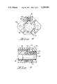
- FIG. 1 is a partially exploded, partially sectioned, perspective view of the subject electrical connector
- FIG. 2 is a partial longitudinal section through the subject connector in an unmated condition
- FIG. 3 is a view similar to FIG. 2 showing the subject connector in the fully mated condition
- FIG. 4 is a transverse section taken along line 4--4 of FIG. 3;
- FIG. 5 is an enlarged detailed view of the sealing diaphragms in sealing engagement with the respective contacts, as shown in FIG. 3;
- FIG. 6 is a longitudinal section through a portion of the connector showing an alternate sealing member for individual conductors.
- FIG. 7 is a longitudinal section through an alternate cable sealing member.
- the subject connector 10 includes a plug member 12 and a receptacle member 14.
- the plug member 12 includes a plug housing 16 having a plurality of contact receiving bores 18 leading to a mating face 20, an outwardly directed, longitudinally extending keying projection 22 terminating at a locking detent 24, and a peripheral groove 26 spaced from the mating face 20.
- a sealing diaphragm 28 is mounted on the mating end of the plug housing by a flange 30 which engages in groove 26.
- a plurality of slots 32 are formed in the diaphragm face, each disposed above one of the respective bores 18.
- a receptacle contact 34 is positioned in each of the bores 18 with the contacts being crimped connected to a like plurality of conductors 36 of a cable 38.
- the cable 38 passes through a cable seal 40 and a strain relief assembly 42.
- the cable seal 40 is a profiled tubular member having an outwardly directed flange 44 at one end and an inwardly directed cable sealing means 46 at the opposite end.
- the cable sealing means 46 is an integral combination of a truncated conical member 48 and cylindrical member 50 the walls of which extend substantially parallel to the jacketing of the cable 38 and define an aperture of lesser internal dimensions than the exterior dimensions of the cable.
- a washer or stiffening ring 52 is mounted on the seal 40 adjacent flange 44 to assure a tight engagement of the seal with the plug housing 16.
- the strain relief assembly 42 includes a tubular member 54 having internal threads 56 on one end adapted to engage with external threads 58 on the plug housing 16 and with clamp means 60 at the opposite end for fixedly engaging the cable 38.
- the clamp means 60 includes a profiled clamping member 62 which is received in a slot 64 in the tubular member 54 and secured therein by threaded members 66.
- the receptacle member 14 is shown in an embodiment adapted to be mounted on a bulkhead 68 or the like through the intermediary of a gasket 70.
- the receptacle member 14 includes a unitary receptacle housing 72 having a tubular central portion 74 closed at one end by a contact receiving portion 76 with a plurality of contact receiving bores 78 therein opening onto mating face 80.
- a male contact 82 is inserted in each of the respective bores 78 and is connected to a respective conductor 84.
- An annular recess 86 forms an extension of the tubular central portion 74 about the contact receiving portion 76.
- the tubular central portion 74 also includes a longitudinally extending keying recess 88, which can best be seen in FIG. 4.
- a hood extension 90 formed by a pair of arcuate members 92 which are slightly spaced at their lower ends, to form a slot 94 therebetween, and are connected at their upper ends to form a latch receiving housing 96.
- a latch member 98 is positioned in the housing 96 and secured by a fixed pin 100.
- An integral flange 102 extends radially outwardly from the periphery of the receptacle housing 72 and is used to mount the receptacle member in the bulkhead or panel 68.
- a sealing diaphragm 104 is fitted within the tubular portion 74 with a keying projection 106 aligned with a keying recess 88 in the housing.
- the sealing diaphragm 104 has a plurality of normally closed slots 108 formed therein and is supported by a rigid backing member 110 having a like plurality of apertures 112 in alignment with slots 108 and the respective contacts 82.
- the backing member also has a keying projection 113.
- a helical compression spring 114 has one end engaged in a peripheral groove 116 in backing member 108 and is held in the housing by means of a set screw 118 which is sealed in the connector housing by a gasket 120.
- the subject connector is assembled in a conventional fashion. Either the contacts 34 are first secured to the respective conductors 36 and then fed through the cable seal or vice versa.
- the cylindrical portion 50 makes sealing engagement with the cable 38 as shown or even when reversed upon itself, as might happen if the cable is inserted too far into the seal and then withdrawn.
- the contacts 34 are then inserted into their respective bores 18 in the plug housing.
- the seal 40 is engaged with the rear end of the plug housing 12 and the strain relief assembly 42 is threaded onto the plug housing 12. During this threading action, the washer 52 prevents twisting of the seal 40 while providing a rigid support for flange 44 of the seal 40.
- the strain relief is applied to the cable by driving member 62 into the slot 64 and securing it therein by means of the threaded members 66.
- the diaphragm 28 is mounted over the free end of the plug housing with the flange 26 engaging in recess 30.
- the receptacle member 14 is assembled in a somewhat similar fashion with the contacts 82 being first engaged with conductors 94 and then inserted into the respective bores 78.
- the diaphragm 104 of the receptacle member is mounted on the support member 110 with the keying projections 106 and 113 in alignment.
- One end of the spring 114 is engaged in the annular groove 116.
- the sealing assembly of the diaphragm, backing member and spring is then inserted, spring first, into the receptacle portion with the spring being received in recess 86 and secured therein by engagement of the screw 118 with the end of the spring.
- the sealing assembly is positioned so that it will not fall out of the receptacle member nor extend too far out of the tubular portion 74 so as to prevent proper sealing of the receptacle member in the unmated condition.
- the latching means 98 is inserted into the housing 96 and secured therein by insertion of the pin 100.
- the pin 100 preferably is a shear pin which will break when a predetermined load is applied to the cable. When the pin breaks, this will allow the connector members to become uncoupled without damaging either the connector or the cable terminations.
- the two members of the connector are thus assembled in a sealed unmated condition, as shown in FIG. 2.
- Either of the connector members can be exposed to the normal atmospheric elements of wind, rain and dust without the contacts themselves being exposed.
- the slot 94 also allows for drainage and prevents buildup of debris at the opening of the receptacle member.
- the connector members are engaged simply by inserting the plug 12 into the receptacle 14.
- the plug has a keyed profile which matches with the profile of the receptacle to assure polarized operation.
- the sealing assembly is pushed backwards against the resistance of the spring 114.
- the contacts 82 are exposed through the respective slots 108 in diaphragm 104 and continue through the slots 32 of the diaphragm 28 to engage in the receptacle contacts 34.
- the force of spring 114 is not sufficient to prevent the insertion of the plug member into the receptacle member, but is sufficient to assure the sealing assembly will take position shown in FIG. 2 under a no-load condition.
- the plug member is fully inserted into the receptacle member when the latching member 98 engages the detent 24.
- the subject plug member can be inserted into the receptacle member using one hand only since there is no need to remove a conventional spring loaded cover prior to making the mating engagement.
- the plug member can be unmated from the receptacle member simply by raising the latch 98 and pulling the plug member from the receptacle member. This also can be accomplished using just one hand.
- the contacts 82 are withdrawn from engagement with the contacts 34 and eventually are withdrawn from the slots 32 as the plug member is completely removed.
- the slots 32 close to seal the contacts 34 within the plug member 12.
- the seal assembly 104 is driven forwardly by the spring 114 until the contacts 82 are withdrawn through the slots 108 which again assume a closed and sealed condition.
- FIG. 6 An alternate embodiment for sealing a cable or individual conductors to the connector are shown in FIG. 6.
- the sealing means 122 is intended for use with individual conductors 124.
- the sealing means 122 is provided with a plurality of bores 126 each having an integral seal formed by a truncated conical portion 128 and continuous cylindrical portion 130 extending substantially parallel to and inwardly of the walls of the bore 126.
- the portion 130 has an inner dimension less than the outer dimensions of the conductor 124 to form a sealing engagement therebetween.
- the sealing means 122 has an outer profile while is adapted to mate with washer 52, the strain relief assembly 42 and the housing 16.
- the alternate sealing means 132 of FIG. 7 is intended for use with cables and includes a rear portion 134 which is substantially identical to that of seal 40. This portion includes a truncated conical flange 136 and integral cylindrical seal 138 which sealingly engage cable 140.
- the forward tubular portion 142 of the sealing means is intended for performing a latching operation with a housing member 144 to obviate the need for separate strain relief member.
- the forward tubular portion 142 includes an inwardly directed annular lip 146 adapted to engage over a step 148 in housing 144.
- a number of latching projections 150 are integral with the free end of the tubular portion 142 and extend radially inwardly to engage with a like number of detents 152 on the outside profile of the receptacle member 154.
Abstract
A sealed electrical connector is disclosed in which both the plug and receptacle portions are completely sealed from the normal atmospheric environment in both the connected and disconnected conditions. Each of the plug and receptacle members is provided with a normally closed sealing diaphragm extending across the mating ends thereof to protect the contacts enclosed thereby from moisture, dirt, etc. The diaphragms are opened, when the connectors are mated, by the male pin contact which extends through both sealing diaphragms to engage in the female receptacle contact. The subject connector obviates the need for a cover, which must be removed prior to mating the plug into the receptacle, and thus mating of the plug into the receptacle can be accomplished using one hand only.
Description
1. Field of the Invention
The present invention relates to an electrical connector which is sealed against the normal atmospheric environment and in particular to an electrical connector in which both the plug and receptacle portions are sealed in both the mated and unmated conditions.
2. The Prior Art
Most electrical connectors have been designed to provide a tight seal against the normal atmospheric environment only when the connector members are mated. Some connectos have a cover or lid which tightly fits over the receptacle portion making it sealed tight in an unmated condition. However, very few electrical connectors provide sealing of the contacts for both the plug and the receptacle members when they are not mated. Even fewer electrical connectors provide sealing for both the plug and the receptacle in the mated and unmated condition and yet can be mated with one hand. Those known connectors that have sealing for both the plug and receptacle generally have some kind of cover or lid which must be removed from at least one or both of the members before they can be properly fully mated.
The present invention achieves sealing of both the plug and receptacle portions of a connector in both the mated and unmated conditions by having a sealing diaphragm extending across the mating faces of each of the plug and receptacle members. Each sealing diaphragm is provided with a plurality of normally closed slots disposed in line with the contacts mounted in the respective members. Upon mating of the connector members, the pin contacts pass through the slots in the respective diaphragms to engage the corresponding receptacle contacts. The diaphragm in the receptacle member is mounted on a spring loaded backing disc which will be driven inwardly of the receptacle member by the plug member to expose the pin contacts therein. Upon unmating of the connector members, the spring loaded disc returns the diaphragm to its original condition with contacts withdrawn from the slots, which assume a sealing condition. The connector also includes sealing means for making an environmental tight seal with both a cable or individual conductors terminated by the connector members.
It is therefore an object of the present invention to produce an improved electrical connector which will provide a tightly sealed enclosure about the contacts of both the plug and the receptacle members, in both mated and unmated conditions, which will protect the contacts against normal atmospheric conditions such as moisture and dirt.
It is a further object of the present invention to produce an improved environmentally sealed electrical connector which can be mated and unmated with a single hand.
It is still another object of the present invention to produce an electrical connector in which the receptacle member is provided with a sealing diaphragm mounted on a spring loaded disc, with the diaphragm having a plurality of slots therein disposed above the associated contacts and in a normal first position conceals the contacts and in the mating second condition is depressed to expose the contacts for mating with contacts of the plug member.
It is a further object of the present invention to produce an improved electrical connector which is particularly suitable for use in the transportation industry to provide sealed electrical interconnection between traction and trailer units.
It is yet another object of the present invention to produce an improved electrical connector which is sealed from the ambient conditions, including moisture and dirt, at all times and thus is particularly useful for providing electrical interconnection between tandem vehicles.
It is yet another object of the present invention to produce an improved connector which is sealed in the mated and unmated conditions and which can be readily and economically manufactured.
The means for accomplishing the foregoing objects and other advantages of the present invention will become apparent to those skilled in the art from the following detailed description taken with reference to the accompanying drawings.
FIG. 1 is a partially exploded, partially sectioned, perspective view of the subject electrical connector;
FIG. 2 is a partial longitudinal section through the subject connector in an unmated condition;
FIG. 3 is a view similar to FIG. 2 showing the subject connector in the fully mated condition;
FIG. 4 is a transverse section taken along line 4--4 of FIG. 3;
FIG. 5 is an enlarged detailed view of the sealing diaphragms in sealing engagement with the respective contacts, as shown in FIG. 3;
FIG. 6 is a longitudinal section through a portion of the connector showing an alternate sealing member for individual conductors; and
FIG. 7 is a longitudinal section through an alternate cable sealing member.
The subject connector 10 includes a plug member 12 and a receptacle member 14. The plug member 12 includes a plug housing 16 having a plurality of contact receiving bores 18 leading to a mating face 20, an outwardly directed, longitudinally extending keying projection 22 terminating at a locking detent 24, and a peripheral groove 26 spaced from the mating face 20. A sealing diaphragm 28 is mounted on the mating end of the plug housing by a flange 30 which engages in groove 26. A plurality of slots 32 are formed in the diaphragm face, each disposed above one of the respective bores 18. A receptacle contact 34 is positioned in each of the bores 18 with the contacts being crimped connected to a like plurality of conductors 36 of a cable 38. The cable 38 passes through a cable seal 40 and a strain relief assembly 42. The cable seal 40 is a profiled tubular member having an outwardly directed flange 44 at one end and an inwardly directed cable sealing means 46 at the opposite end. The cable sealing means 46 is an integral combination of a truncated conical member 48 and cylindrical member 50 the walls of which extend substantially parallel to the jacketing of the cable 38 and define an aperture of lesser internal dimensions than the exterior dimensions of the cable. A washer or stiffening ring 52 is mounted on the seal 40 adjacent flange 44 to assure a tight engagement of the seal with the plug housing 16. The strain relief assembly 42 includes a tubular member 54 having internal threads 56 on one end adapted to engage with external threads 58 on the plug housing 16 and with clamp means 60 at the opposite end for fixedly engaging the cable 38. The clamp means 60 includes a profiled clamping member 62 which is received in a slot 64 in the tubular member 54 and secured therein by threaded members 66.
The receptacle member 14 is shown in an embodiment adapted to be mounted on a bulkhead 68 or the like through the intermediary of a gasket 70. The receptacle member 14 includes a unitary receptacle housing 72 having a tubular central portion 74 closed at one end by a contact receiving portion 76 with a plurality of contact receiving bores 78 therein opening onto mating face 80. A male contact 82 is inserted in each of the respective bores 78 and is connected to a respective conductor 84. An annular recess 86 forms an extension of the tubular central portion 74 about the contact receiving portion 76. The tubular central portion 74 also includes a longitudinally extending keying recess 88, which can best be seen in FIG. 4. At the forward end of the tubular portion 74 there is a hood extension 90 formed by a pair of arcuate members 92 which are slightly spaced at their lower ends, to form a slot 94 therebetween, and are connected at their upper ends to form a latch receiving housing 96. A latch member 98 is positioned in the housing 96 and secured by a fixed pin 100. An integral flange 102 extends radially outwardly from the periphery of the receptacle housing 72 and is used to mount the receptacle member in the bulkhead or panel 68. A sealing diaphragm 104 is fitted within the tubular portion 74 with a keying projection 106 aligned with a keying recess 88 in the housing. The sealing diaphragm 104 has a plurality of normally closed slots 108 formed therein and is supported by a rigid backing member 110 having a like plurality of apertures 112 in alignment with slots 108 and the respective contacts 82. The backing member also has a keying projection 113. A helical compression spring 114 has one end engaged in a peripheral groove 116 in backing member 108 and is held in the housing by means of a set screw 118 which is sealed in the connector housing by a gasket 120.
The subject connector is assembled in a conventional fashion. Either the contacts 34 are first secured to the respective conductors 36 and then fed through the cable seal or vice versa. The cylindrical portion 50 makes sealing engagement with the cable 38 as shown or even when reversed upon itself, as might happen if the cable is inserted too far into the seal and then withdrawn. The contacts 34 are then inserted into their respective bores 18 in the plug housing. The seal 40 is engaged with the rear end of the plug housing 12 and the strain relief assembly 42 is threaded onto the plug housing 12. During this threading action, the washer 52 prevents twisting of the seal 40 while providing a rigid support for flange 44 of the seal 40. The strain relief is applied to the cable by driving member 62 into the slot 64 and securing it therein by means of the threaded members 66. The diaphragm 28 is mounted over the free end of the plug housing with the flange 26 engaging in recess 30.
The receptacle member 14 is assembled in a somewhat similar fashion with the contacts 82 being first engaged with conductors 94 and then inserted into the respective bores 78. The diaphragm 104 of the receptacle member is mounted on the support member 110 with the keying projections 106 and 113 in alignment. One end of the spring 114 is engaged in the annular groove 116. The sealing assembly of the diaphragm, backing member and spring is then inserted, spring first, into the receptacle portion with the spring being received in recess 86 and secured therein by engagement of the screw 118 with the end of the spring. Thus the sealing assembly is positioned so that it will not fall out of the receptacle member nor extend too far out of the tubular portion 74 so as to prevent proper sealing of the receptacle member in the unmated condition. The latching means 98 is inserted into the housing 96 and secured therein by insertion of the pin 100.
The pin 100 preferably is a shear pin which will break when a predetermined load is applied to the cable. When the pin breaks, this will allow the connector members to become uncoupled without damaging either the connector or the cable terminations.
The two members of the connector are thus assembled in a sealed unmated condition, as shown in FIG. 2. Either of the connector members can be exposed to the normal atmospheric elements of wind, rain and dust without the contacts themselves being exposed. Thus there is a potential for great life expectancy for the contacts since they would not be likely to be exposed to an atmosphere or environment which would be condusive to corrosion or to the introduction of material which would prevent making a good electrical contact between contacts 34 and 82. The slot 94 also allows for drainage and prevents buildup of debris at the opening of the receptacle member.
The connector members are engaged simply by inserting the plug 12 into the receptacle 14. The plug has a keyed profile which matches with the profile of the receptacle to assure polarized operation. When the mating face of the plug member engages the diaphragm 104, the sealing assembly is pushed backwards against the resistance of the spring 114. As the sealing assembly is depressed, the contacts 82 are exposed through the respective slots 108 in diaphragm 104 and continue through the slots 32 of the diaphragm 28 to engage in the receptacle contacts 34. The force of spring 114 is not sufficient to prevent the insertion of the plug member into the receptacle member, but is sufficient to assure the sealing assembly will take position shown in FIG. 2 under a no-load condition. The plug member is fully inserted into the receptacle member when the latching member 98 engages the detent 24.
From the foregoing it is quite apparent that the subject plug member can be inserted into the receptacle member using one hand only since there is no need to remove a conventional spring loaded cover prior to making the mating engagement. Likewise the plug member can be unmated from the receptacle member simply by raising the latch 98 and pulling the plug member from the receptacle member. This also can be accomplished using just one hand.
As the plug member is removed from the receptacle member, the contacts 82 are withdrawn from engagement with the contacts 34 and eventually are withdrawn from the slots 32 as the plug member is completely removed. The slots 32 close to seal the contacts 34 within the plug member 12. Simultaneously with this movement, the seal assembly 104 is driven forwardly by the spring 114 until the contacts 82 are withdrawn through the slots 108 which again assume a closed and sealed condition.
An alternate embodiment for sealing a cable or individual conductors to the connector are shown in FIG. 6. In the alternate embodiment the sealing means 122 is intended for use with individual conductors 124. The sealing means 122 is provided with a plurality of bores 126 each having an integral seal formed by a truncated conical portion 128 and continuous cylindrical portion 130 extending substantially parallel to and inwardly of the walls of the bore 126. The portion 130 has an inner dimension less than the outer dimensions of the conductor 124 to form a sealing engagement therebetween. The sealing means 122 has an outer profile while is adapted to mate with washer 52, the strain relief assembly 42 and the housing 16.
The alternate sealing means 132 of FIG. 7 is intended for use with cables and includes a rear portion 134 which is substantially identical to that of seal 40. This portion includes a truncated conical flange 136 and integral cylindrical seal 138 which sealingly engage cable 140. The forward tubular portion 142 of the sealing means is intended for performing a latching operation with a housing member 144 to obviate the need for separate strain relief member. The forward tubular portion 142 includes an inwardly directed annular lip 146 adapted to engage over a step 148 in housing 144. A number of latching projections 150 are integral with the free end of the tubular portion 142 and extend radially inwardly to engage with a like number of detents 152 on the outside profile of the receptacle member 154.
The present invention may be subject to many changes and modifications without departing from the spirit or essential characteristics thereof. The present embodiments are therefore to be considered in all respects as illustrative and not restrictive of the scope of the invention.
Claims (28)
1. An electrical connector which is sealed in a weather tight condition in both the mated and unmated conditions, said connector comprising:
a plug member including a housing having a mating face on one end, a plurality of contact receiving bores passing through said housing and opening onto said mating face, a like plurality of contacts each connected to a respective one of a plurality of conductors of a cable and received in a respective one of said bores with said contact directed towards said mating face, first sealing means covering said mating face of said connector, said first sealing means having a like plurality of normally closed slots each positioned in alignment with a respective one of said bores and said contacts, and second sealing means at the other end of said member effecting a fluid tight seal between said cable and said plug member;
a receptacle member including a plug member receiving recess closed at one end by a contact receiving block with a mating face directed inwardly of said recess, a plurality of contact receiving bores in said block leading to said mating face, a sealing assembly mounted for reciprocal movement in said recess, said sealing assembly including a sealing diaphragm having an outer periphery in wiping engagement with the inner periphery of said plug member receiving recess and a plurality of normally closed slots therein each disposed above a respective one of said contact bores, a rigid support plate having apertures therein aligned with said slots, a spring member attached to said plate and said receptacle housing allowing limited reciprocal movement of said sealing assembly within said recess and a hood extending from said receptacle housing substantially enclosing said plug receiving recess, a slot in said hood extending the length of a bottom portion thereof whereby a buildup of moisture and particles in said hood is prevented; and
latching means adapted to secure said plug member and said receptacle member together in a mated condition and including a detent on one of said members and a latching lever operatively mounted on the other of said members to resiliently engage said detent.
2. A sealed electrical connector according to claim 1 wherein said latching means comprises:
a fixed detent on said plug member, and
a latching lever operatively mounted on said receptacle member to resiliently engage said detent.
3. A sealed electrical connector according to claim 1 further comprising:
an outwardly directed mounting flange integral with said receptacle member whereby said member can be mounted on a bulkhead.
4. A sealed electrical connector according to claim 1 wherein said second sealing means effects a fluid tight seal between each of a plurality of conductors attached to the respective contacts and said plug member, said second sealing means having an outer profile matching that of said plug member housing and a plurality of profiled conductor sealing apertures each defined by an integral truncated conical portion and a cylindrical portion, the inner dimension of said cylindrical portion being less than the outer dimension of the conductor received therein.
5. A sealed electrical connector according to claim 1 wherein said contacts in said plug member are receptacle contacts and said contacts in said receptacle member are pin contacts which extend through the respective slots in said sealing means and said sealing assembly to mate with the corresponding receptacle contacts.
6. A sealed electrical connector according to claim 1 wherein said first sealing means on said plug member further comprises an integral outwardly directed flange effecting sealing engagement between said plug and said receptacle members in the mated condition.
7. A sealed electrical connector according to claim 1 wherein said second sealing means comprises cable sealing means effecting a fluid tight seal between the conductor cable and said plug member, said cable sealing means comprising a substantially tubular unit having a radially outwardly flared flange at one end mating with the profile of said plug member,
a profiled cable engaging seal on the other end including an integral assembly of a truncated conical portion and a cylindrical portion having an internal diameter of lesser dimensions than the external diameter of said cable whereby sealing engagement therebetween is effected, and
means to tightly secure said flange against said plug member.
8. A sealed electrical connector according to claim 7 further comprising:
an annular member engaging said flange, and
said means to tightly secure said flange comprises an annular threaded member having an inwardly directed flange engaging said annular member and with the threaded portion engaging said connector member.
9. A sealed electrical connector according to claim 1 further comprising a strain relief assembly,
said assembly including a rigid tubular member having means on a first end to detachably engage said connector member and cable clamping means on the other end to grip at least one conductor therein.
10. A sealed electrical connector according to claim 9 wherein said at least one conductor comprises an electrical cable.
11. A sealed plug member for an electrical connector, said plug member comprising:
a housing having a mating face on one end and at least one contact receiving bore leading to said face and, a groove about the periphery of said housing spaced from said mating face,
a like number of contacts each connected to a respective conductor and received in a respective one of said bores directed toward said mating face,
first sealing means enclosing said mating face, said first sealing means including a diaphragm portion extending across said mating face and an integral flange portion having an inwardly directed lip engaging in said groove, said first sealing means having a normally closed slot disposed over each said bore, said normally closed slot being in said diaphragm portion, and
second sealing means at the other end of said housing effecting a fluid tight seal between said conductors and said housing.
12. A sealed plug member according to claim 11 further comprising:
a radially outwardly directed flange integral with said first sealing member for effecting a wiping and sealing engagement with a respective receptacle member.
13. A sealed plug member according to claim 11 further comprising:
means to secure said plug member in a respective receptacle member.
14. A sealed plug member according to claim 11 further comprising:
a conductor strain relief assembly including a rigid member having means on one end to detachably engage said housing and means on the other to fixedly engage at least one conductor.
15. A sealed plug member according to claim 11 wherein said housing has a profiled cross section for keyed mating of said plug in a respective receptacle member.
16. A sealed plug member according to claim 11 wherein said contacts are receptacle contacts.
17. A sealed plug member according to claim 11 further comprising:
a second sealing member having integral first flange means engaging with said housing, and
integral second flange means defining at least one restricted opening having an inner diameter less than the outer diameter of a conductor received therein to effect a seal therebetween.
18. A sealed plug member according to claim 17 wherein said second sealing member is substantially planar and a plurality of second flange means are formed therein.
19. A sealed plug member according to claim 17 wherein said second sealing member is substantially tubular with said first flange means on one end and said second flange means on the other end.
20. A sealed plug member according to claim 17 further comprising:
means to secure said second sealing member to said housing comprising an annular member having means to detachably engage said housing and to bias said sealing member against said housing.
21. A sealed receptacle member for an electrical connector, said member comprising:
a housing defining a plug receiving recess and hood means projecting from said housing and surrounding said recess, and a slot in said hood means extending the length of a bottom portion thereof whereby buildup of moisture and debris in said hood means is prevented,
a contact block closing one end of said recess with a mating face directed into said recess, a plurality of contact receiving bores in said block opening onto said mating face, and a like plurality of contacts each connected to a respective conductor of a cable and mounted in a respective one of said bores with said contact directed toward said mating face,
a sealing assembly comprising a diaphragm having an outer perphery in wiping engagement with inner periphery of said plug receiving recess, said diaphragm having a plurality of normally closed slots disposed in alignment with each said contact receiving bore, a rigid plate having a plurality of apertures in allignment with said slots and supporting said diaphragm substantially across the entire surface thereof, and spring means resiliently securing said assembly for reciprocal movement within said recess, and
latching means adapted to secure a plug member therein in a mated condition.
22. A sealed receptacle member according to claim 2 further comprising:
flange means integral with said housing to mount said member on a panel.
23. A sealed receptacle member according to claim 2 wherein said recess has a profiled cross section to provide polarized mating of a corresponding plug member
24. A second receptacle member according to claim 21 wherein:
said latching means comprises a resiliently mounted lever in said housing adapted to engage and secure a plug member received in said receptacle member.
25. A sealed receptacle member according to claim 21 further comprising:
means mounting said latching means in said housing, said mounting means having a predetermined shear strength whereby said latching means will release upon application of sufficient force to a plug member secured thereby before damage occurs to said connector.
26. A sealed receptacle member according to claim 21 further comprising:
a sealing member having integral first flange means engaging with said housing, and
integral second flange means defining at least one restricted opening having an inner diameter less than the outer diameter of a conductor received therein to effect a seal therebetween.
27. A sealed receptacle member according to claim 21 further comprising:
a conductor strain relief assembly including a rigid member having means on one end to detachably engage said housing and means on the other end to fixedly engage at least one conductor.
28. A sealed receptacle member according to claim 21 wherein said contacts comprise pin contacts capable of projecting through said slots upon depression of said sealing assembly whereby mating with corresponding contacts is effected.
Priority Applications (13)
| Application Number | Priority Date | Filing Date | Title |
|---|---|---|---|
| US05/585,622 US4109989A (en) | 1975-06-10 | 1975-06-10 | Environmentally sealed electrical connector |
| CA252,780A CA1066789A (en) | 1975-06-10 | 1976-05-18 | Plug and socket connector assembly with diaphragm sealed contact pins |
| AU14118/76A AU504615B2 (en) | 1975-06-10 | 1976-05-20 | Electrical connector assemblies |
| GB20795/76A GB1503275A (en) | 1975-06-10 | 1976-05-20 | Electrical connector assemblies |
| NL7605602A NL7605602A (en) | 1975-06-10 | 1976-05-25 | PLUG CONNECTOR AND ELECTRICAL CONNECTION SYSTEM EQUIPPED WITH SUCH PLUG CONNECTOR. |
| IT23715/76A IT1060692B (en) | 1975-06-10 | 1976-05-26 | REFERENCES CONCERNING ASSEMBLIES OF ELECTRIC CONNECTORS |
| BR3511/76A BR7603511A (en) | 1975-06-10 | 1976-06-01 | OUTLET CONNECTOR IMPROVEMENTS |
| ES448516A ES448516A1 (en) | 1975-06-10 | 1976-06-03 | Environmentally sealed electrical connector |
| DE19762625648 DE2625648A1 (en) | 1975-06-10 | 1976-06-08 | CONTACT PLUG AND CONNECTION OF CONTACT PLUG AND CONTACT SOCKET |
| FR7617388A FR2314595A1 (en) | 1975-06-10 | 1976-06-09 | CONNECTION SHEET |
| SE7606599A SE411820B (en) | 1975-06-10 | 1976-06-10 | PINS CONTACT ORDER |
| AR263581A AR210497A1 (en) | 1975-06-10 | 1976-06-10 | A MALE CONNECTOR FOR CONJUGATED LINKAGE WITH A FEMALE CONNECTOR |
| JP51068185A JPS51150686A (en) | 1975-06-10 | 1976-06-10 | Electric connector device |
Applications Claiming Priority (1)
| Application Number | Priority Date | Filing Date | Title |
|---|---|---|---|
| US05/585,622 US4109989A (en) | 1975-06-10 | 1975-06-10 | Environmentally sealed electrical connector |
Publications (1)
| Publication Number | Publication Date |
|---|---|
| US4109989A true US4109989A (en) | 1978-08-29 |
Family
ID=24342235
Family Applications (1)
| Application Number | Title | Priority Date | Filing Date |
|---|---|---|---|
| US05/585,622 Expired - Lifetime US4109989A (en) | 1975-06-10 | 1975-06-10 | Environmentally sealed electrical connector |
Country Status (13)
| Country | Link |
|---|---|
| US (1) | US4109989A (en) |
| JP (1) | JPS51150686A (en) |
| AR (1) | AR210497A1 (en) |
| AU (1) | AU504615B2 (en) |
| BR (1) | BR7603511A (en) |
| CA (1) | CA1066789A (en) |
| DE (1) | DE2625648A1 (en) |
| ES (1) | ES448516A1 (en) |
| FR (1) | FR2314595A1 (en) |
| GB (1) | GB1503275A (en) |
| IT (1) | IT1060692B (en) |
| NL (1) | NL7605602A (en) |
| SE (1) | SE411820B (en) |
Cited By (67)
| Publication number | Priority date | Publication date | Assignee | Title |
|---|---|---|---|---|
| US4245875A (en) * | 1979-06-18 | 1981-01-20 | Amp Incorporated | Heavy duty plug and socket |
| WO1983000935A1 (en) * | 1981-09-10 | 1983-03-17 | Trw Inc | Connector assembly |
| US4545632A (en) * | 1982-11-26 | 1985-10-08 | Robert Bosch Gmbh | Modular electrical distribution connection set |
| US4589492A (en) * | 1984-10-10 | 1986-05-20 | Hughes Tool Company | Subsea well submersible pump installation |
| US4775327A (en) * | 1987-02-17 | 1988-10-04 | Amphenol Corporation | Connector with automatic protection cap |
| US4795354A (en) * | 1987-09-03 | 1989-01-03 | Gte Products Corporation | Dust cover for printed circuit board card connector |
| US4808127A (en) * | 1985-10-18 | 1989-02-28 | Arbus, Inc. | Connector assembly |
| US4810202A (en) * | 1983-04-14 | 1989-03-07 | Ab Stratos | Connector device |
| US4824390A (en) * | 1988-02-08 | 1989-04-25 | Gte Products Corporation | Coated electrical connector |
| DE4015793A1 (en) * | 1989-05-31 | 1990-12-06 | Yazaki Corp | Double water-sealed electrical connector - has individual cable seals and single cover seal unit |
| US5080604A (en) * | 1990-11-13 | 1992-01-14 | Amp Incorporated | Self-aligning electrical connector assembly for flat power cable terminations |
| US5154629A (en) * | 1990-08-08 | 1992-10-13 | Icontec, Inc. | Energy transmission cable connector with latching mechanism |
| US5178552A (en) * | 1990-08-28 | 1993-01-12 | Yazaki Corporation | Connector |
| US5197900A (en) * | 1990-12-21 | 1993-03-30 | Icontec, Inc. | Energy transmission cable connector with interchangeable locking mechanisms |
| US5226827A (en) * | 1990-12-06 | 1993-07-13 | Merlin Gerin | Test connector |
| GB2264201A (en) * | 1992-02-13 | 1993-08-18 | Swift 943 Ltd | Electrical connector |
| US5269696A (en) * | 1991-09-13 | 1993-12-14 | Sumitomo Wiring Systems, Ltd. | Connector assembly |
| US5374777A (en) * | 1990-06-01 | 1994-12-20 | Swf Auto-Electric | Connecting device for contact members and electric switch |
| US5382174A (en) * | 1992-03-19 | 1995-01-17 | The Whitaker Corporation | Waterproof electrical connector |
| US5383792A (en) * | 1989-02-21 | 1995-01-24 | The Whitaker Corporation | Insertable latch means for use in an electrical connector |
| WO1995018474A1 (en) * | 1993-12-30 | 1995-07-06 | Ab Volvo | Surface cover for an electric coupling unit and a method for applying said surface cover |
| US5466164A (en) * | 1993-03-09 | 1995-11-14 | Sumitomo Wiring Systems, Ltd. | Connector having a protective hood |
| US5472352A (en) * | 1993-11-24 | 1995-12-05 | Sumitomo Wiring Systems, Ltd. | Waterproofing assembly for connector |
| US5580282A (en) * | 1994-01-14 | 1996-12-03 | Emerson Electric Co. | Sealable shaped connector block for a terminal assembly |
| US5713752A (en) * | 1995-07-21 | 1998-02-03 | The Whitaker Corporation | Latchable electrical connector |
| US5741156A (en) * | 1996-11-08 | 1998-04-21 | The Whitaker Corporation | Protective cover for electrical connector |
| US5899766A (en) * | 1997-09-23 | 1999-05-04 | W.W. Fisher, S.A. | Electrical connector system |
| US6007362A (en) * | 1997-12-09 | 1999-12-28 | The Whitaker Corporation | Electrical connector assembly for a refrigerator door |
| US6036521A (en) * | 1998-03-20 | 2000-03-14 | Electrical Wiring And Connectors Application | Isolating circuits in electrical connector systems |
| US6176739B1 (en) | 1997-02-20 | 2001-01-23 | The Whitaker Corporation | Sealed electrical conductor assembly |
| FR2803111A1 (en) * | 1999-12-23 | 2001-06-29 | Cinch Connecteurs Sa | Open position protection electrical connection unit having male/female section with intermediate grid solidifying during attachment and decoupling/freeing. |
| EP1150393A2 (en) * | 2000-04-25 | 2001-10-31 | Sumitomo Wiring Systems, Ltd. | Connector |
| US6334785B2 (en) * | 2000-03-10 | 2002-01-01 | Yazaki Corporation | Connector sealing structure |
| US6422884B1 (en) * | 2000-06-27 | 2002-07-23 | Sentinel Lighting Wiring Systems, Inc. | Pre-wired circuit component for flexible wiring system |
| US6485322B1 (en) * | 1999-10-01 | 2002-11-26 | Jds Uniphase Corporation | Removable latch and bezel EMI grounding feature for fiber-optic transceivers |
| US6516129B2 (en) * | 2001-06-28 | 2003-02-04 | Jds Uniphase Corporation | Processing protective plug insert for optical modules |
| US6767218B2 (en) * | 2001-04-10 | 2004-07-27 | Koninklijke Philips Electronics N.V. | Quick release mechanical connector including protected electrical connector |
| US20050176265A1 (en) * | 2002-05-03 | 2005-08-11 | Jacobs John D. | Contact insert cartridge for plugs of tractor/trailer jumper cables |
| US20050260883A1 (en) * | 2004-05-19 | 2005-11-24 | Sumitomo Wiring Systems, Ltd. | Connector device |
| USRE39093E1 (en) * | 1993-07-13 | 2006-05-09 | Duraline, A Division Of J.B. Nottingham Co., Inc. | Mast-type outdoor lighting system |
| WO2006081820A1 (en) * | 2005-02-01 | 2006-08-10 | Terma A/S | Uncoupling mechanism for male and female connectors |
| US7104818B1 (en) * | 2005-09-14 | 2006-09-12 | Chi-Tsai Chang | Receptacle structure |
| DK200500150A (en) * | 2005-02-01 | 2006-10-03 | Terma As | Disconnecting mechanism for male and female coupling devices |
| US20070072461A1 (en) * | 2005-03-24 | 2007-03-29 | Libby Williams | Electrical Connector Assembly |
| DE102007010266B3 (en) * | 2007-03-02 | 2008-07-31 | Tyco Electronics Amp Gmbh | Strain relief for prevention of fretting corrosion at contact point, has connecting link with fixed electrical or optical bush, where connecting link and connector are relatively movable against each other |
| US20080242136A1 (en) * | 2007-03-30 | 2008-10-02 | Ball-It Oy | Airtight electrical socket |
| US20090325408A1 (en) * | 2008-06-30 | 2009-12-31 | Marvin Wong | Single Use Connector For Pulse Oximetry Sensors |
| CN101908695A (en) * | 2010-06-21 | 2010-12-08 | 贵州航天电器股份有限公司 | Pneumoelectric mixed loading separate connector |
| US20110237098A1 (en) * | 2008-12-18 | 2011-09-29 | Shigeru Tajima | Plug, plug receptacle and electric power supplying system |
| EP2390968A1 (en) * | 2010-05-25 | 2011-11-30 | Faster S.P.A. | Connector to simultaneously connect a plurality of electrical lines adapted to make the connection in two separate phases |
| US20120003861A1 (en) * | 2010-07-02 | 2012-01-05 | Lear Corporation | connector assembly for vehicle charging |
| US20120045924A1 (en) * | 2010-08-17 | 2012-02-23 | Souriau Usa, Inc. | Flexible breakaway connector |
| WO2012112343A1 (en) | 2011-02-17 | 2012-08-23 | Tyco Electronics Raychem Bvba | Optical fiber sealing element comprising a self-healing member and sealed alignment system and method |
| CN103181034A (en) * | 2010-10-20 | 2013-06-26 | 松下电器产业株式会社 | Electric vehicle charging device |
| WO2013119276A1 (en) * | 2012-02-07 | 2013-08-15 | R.A. Phillips Industries, Inc. | Jumper cable plug with moisture resistant seal |
| US8540527B2 (en) | 2011-02-07 | 2013-09-24 | R.A. Phillips Industries, Inc. | Jumper cable plug with moisture resistant seal |
| US20140242848A1 (en) * | 2013-02-27 | 2014-08-28 | Apple Inc. | Electrical connector having a designed breaking strength |
| US20140335711A1 (en) * | 2012-09-28 | 2014-11-13 | Atlantic Great Dane, Inc. | Power supply system including panel with safety release |
| WO2016033757A1 (en) | 2014-09-03 | 2016-03-10 | Micro Motion, Inc. | Connector with latch |
| US9300080B2 (en) | 2013-03-15 | 2016-03-29 | R.A. Phillips Industries, Inc. | Twist lock connector assembly |
| US9466913B2 (en) | 2012-12-17 | 2016-10-11 | Harting Electric Gmbh & Co. Kg | Car charging connector |
| US20170098907A1 (en) * | 2015-06-04 | 2017-04-06 | Alltop Electronics (Suzhou) Ltd. | Electrical connector |
| US20170352978A1 (en) * | 2016-06-01 | 2017-12-07 | Hubbell Incorporated | Water resistant electrical devices |
| US11121498B2 (en) | 2016-06-01 | 2021-09-14 | Hubbell Incorporated | Water resistant electrical devices |
| US11189961B2 (en) * | 2019-03-09 | 2021-11-30 | Suburban Marine, INC. | Modular harsh environment connector |
| US20220360032A1 (en) * | 2021-05-07 | 2022-11-10 | Cummins Inc. | Electrical interconnect system for an electric vehicle |
| US20230142655A1 (en) * | 2021-11-09 | 2023-05-11 | Fred Bray | Detachable plug |
Families Citing this family (8)
| Publication number | Priority date | Publication date | Assignee | Title |
|---|---|---|---|---|
| US4629269A (en) * | 1977-10-25 | 1986-12-16 | Allied Corporation | Electrical connector with environmental seal |
| US4173349A (en) * | 1978-08-24 | 1979-11-06 | General Motors Corporation | Connector interface sealing arrangement |
| DE3305156A1 (en) * | 1982-03-29 | 1983-10-06 | Automation Ind Inc | ELECTRICAL CONNECTOR |
| GB8319630D0 (en) * | 1983-07-20 | 1983-08-24 | Icore Int Ltd | Device for terminating electrical cable |
| GB2149589B (en) * | 1983-11-08 | 1988-06-02 | Davis & Son John | A connector for releasable connection of a first to a second apparatus |
| FR2614474B1 (en) * | 1987-04-23 | 1993-03-12 | Legrand Sa | SOCKET SOCKET WITH RETRACTABLE AND WATERPROOF SHUTTER |
| DE202007017488U1 (en) * | 2007-12-14 | 2009-04-23 | Grawe, Quirin | plug assembly |
| DE202009004604U1 (en) * | 2009-03-06 | 2009-06-10 | Franz Binder Gmbh + Co. Elektrische Bauelemente Kg | Connectors |
Citations (12)
| Publication number | Priority date | Publication date | Assignee | Title |
|---|---|---|---|---|
| SU274176A1 (en) * | Л. Л. Пискорский, А. С. Портнов, Фейгин, Л. Д. Хромйв, С. С. Черногородов , М. Л. Шлионскнй | SEALED PLUG CONNECTOR | ||
| US2194769A (en) * | 1938-05-27 | 1940-03-26 | Pyle National Co | Connector |
| US2409650A (en) * | 1943-06-15 | 1946-10-22 | Irene Lane Wiggins | Coupling |
| DE901187C (en) * | 1951-09-26 | 1954-01-07 | Siemens Ag | Device for connecting or connecting electrical high-voltage cables |
| US2858518A (en) * | 1957-05-01 | 1958-10-28 | Gen Dynamics Corp | Fluid tight electrical connection |
| FR1255427A (en) * | 1960-01-26 | 1961-03-10 | Jaeger Ets Ed | Improvements to multiple electrical connection equipment |
| US3072021A (en) * | 1961-02-23 | 1963-01-08 | Lewis J Marcon | Missile umbilical assembly |
| FR1391459A (en) * | 1964-04-27 | 1965-03-05 | Multi-pole plug coupling for electric cables | |
| DE1202374B (en) * | 1962-10-03 | 1965-10-07 | Bbc Brown Boveri & Cie | Electric coupling consisting of two coupling parts |
| US3378811A (en) * | 1966-01-10 | 1968-04-16 | Youngstown Sheet And Tube Co | Downhole electrical connector apparatus and method of connecting same |
| US3519975A (en) * | 1968-03-25 | 1970-07-07 | Itt | Electrical connector |
| US3742426A (en) * | 1971-05-20 | 1973-06-26 | Amp Inc | Fire resistant pluggable contact and receptacle |
Family Cites Families (6)
| Publication number | Priority date | Publication date | Assignee | Title |
|---|---|---|---|---|
| US2892991A (en) * | 1955-12-29 | 1959-06-30 | Deutsch Co | Electrical connector |
| FR1273012A (en) * | 1960-08-25 | 1961-10-06 | Waterproof power outlet | |
| US3120987A (en) * | 1961-02-21 | 1964-02-11 | Hubbell Inc Harvey | Electrical cord connector having an improved protective covering |
| US3657681A (en) * | 1969-05-29 | 1972-04-18 | Deep Oil Technology Inc | Self-purging multi-contact electrical connector |
| US3880487A (en) * | 1973-07-20 | 1975-04-29 | Itt | Low cost sealed connector |
| US3843853A (en) * | 1973-11-15 | 1974-10-22 | Itt | Electrical connector with switch and latch means therefore |
-
1975
- 1975-06-10 US US05/585,622 patent/US4109989A/en not_active Expired - Lifetime
-
1976
- 1976-05-18 CA CA252,780A patent/CA1066789A/en not_active Expired
- 1976-05-20 AU AU14118/76A patent/AU504615B2/en not_active Expired
- 1976-05-20 GB GB20795/76A patent/GB1503275A/en not_active Expired
- 1976-05-25 NL NL7605602A patent/NL7605602A/en not_active Application Discontinuation
- 1976-05-26 IT IT23715/76A patent/IT1060692B/en active
- 1976-06-01 BR BR3511/76A patent/BR7603511A/en unknown
- 1976-06-03 ES ES448516A patent/ES448516A1/en not_active Expired
- 1976-06-08 DE DE19762625648 patent/DE2625648A1/en not_active Withdrawn
- 1976-06-09 FR FR7617388A patent/FR2314595A1/en active Pending
- 1976-06-10 JP JP51068185A patent/JPS51150686A/en active Pending
- 1976-06-10 SE SE7606599A patent/SE411820B/en unknown
- 1976-06-10 AR AR263581A patent/AR210497A1/en active
Patent Citations (12)
| Publication number | Priority date | Publication date | Assignee | Title |
|---|---|---|---|---|
| SU274176A1 (en) * | Л. Л. Пискорский, А. С. Портнов, Фейгин, Л. Д. Хромйв, С. С. Черногородов , М. Л. Шлионскнй | SEALED PLUG CONNECTOR | ||
| US2194769A (en) * | 1938-05-27 | 1940-03-26 | Pyle National Co | Connector |
| US2409650A (en) * | 1943-06-15 | 1946-10-22 | Irene Lane Wiggins | Coupling |
| DE901187C (en) * | 1951-09-26 | 1954-01-07 | Siemens Ag | Device for connecting or connecting electrical high-voltage cables |
| US2858518A (en) * | 1957-05-01 | 1958-10-28 | Gen Dynamics Corp | Fluid tight electrical connection |
| FR1255427A (en) * | 1960-01-26 | 1961-03-10 | Jaeger Ets Ed | Improvements to multiple electrical connection equipment |
| US3072021A (en) * | 1961-02-23 | 1963-01-08 | Lewis J Marcon | Missile umbilical assembly |
| DE1202374B (en) * | 1962-10-03 | 1965-10-07 | Bbc Brown Boveri & Cie | Electric coupling consisting of two coupling parts |
| FR1391459A (en) * | 1964-04-27 | 1965-03-05 | Multi-pole plug coupling for electric cables | |
| US3378811A (en) * | 1966-01-10 | 1968-04-16 | Youngstown Sheet And Tube Co | Downhole electrical connector apparatus and method of connecting same |
| US3519975A (en) * | 1968-03-25 | 1970-07-07 | Itt | Electrical connector |
| US3742426A (en) * | 1971-05-20 | 1973-06-26 | Amp Inc | Fire resistant pluggable contact and receptacle |
Cited By (99)
| Publication number | Priority date | Publication date | Assignee | Title |
|---|---|---|---|---|
| US4245875A (en) * | 1979-06-18 | 1981-01-20 | Amp Incorporated | Heavy duty plug and socket |
| WO1983000935A1 (en) * | 1981-09-10 | 1983-03-17 | Trw Inc | Connector assembly |
| US4411491A (en) * | 1981-09-10 | 1983-10-25 | Trw Inc. | Connector assembly with elastomeric sealing membranes having slits |
| US4545632A (en) * | 1982-11-26 | 1985-10-08 | Robert Bosch Gmbh | Modular electrical distribution connection set |
| US4810202A (en) * | 1983-04-14 | 1989-03-07 | Ab Stratos | Connector device |
| US4589492A (en) * | 1984-10-10 | 1986-05-20 | Hughes Tool Company | Subsea well submersible pump installation |
| US4808127A (en) * | 1985-10-18 | 1989-02-28 | Arbus, Inc. | Connector assembly |
| US4775327A (en) * | 1987-02-17 | 1988-10-04 | Amphenol Corporation | Connector with automatic protection cap |
| US4795354A (en) * | 1987-09-03 | 1989-01-03 | Gte Products Corporation | Dust cover for printed circuit board card connector |
| US4824390A (en) * | 1988-02-08 | 1989-04-25 | Gte Products Corporation | Coated electrical connector |
| US5383792A (en) * | 1989-02-21 | 1995-01-24 | The Whitaker Corporation | Insertable latch means for use in an electrical connector |
| DE4015793A1 (en) * | 1989-05-31 | 1990-12-06 | Yazaki Corp | Double water-sealed electrical connector - has individual cable seals and single cover seal unit |
| US5374777A (en) * | 1990-06-01 | 1994-12-20 | Swf Auto-Electric | Connecting device for contact members and electric switch |
| US5154629A (en) * | 1990-08-08 | 1992-10-13 | Icontec, Inc. | Energy transmission cable connector with latching mechanism |
| US5178552A (en) * | 1990-08-28 | 1993-01-12 | Yazaki Corporation | Connector |
| US5080604A (en) * | 1990-11-13 | 1992-01-14 | Amp Incorporated | Self-aligning electrical connector assembly for flat power cable terminations |
| US5226827A (en) * | 1990-12-06 | 1993-07-13 | Merlin Gerin | Test connector |
| US5197900A (en) * | 1990-12-21 | 1993-03-30 | Icontec, Inc. | Energy transmission cable connector with interchangeable locking mechanisms |
| US5269696A (en) * | 1991-09-13 | 1993-12-14 | Sumitomo Wiring Systems, Ltd. | Connector assembly |
| GB2264201A (en) * | 1992-02-13 | 1993-08-18 | Swift 943 Ltd | Electrical connector |
| US5334032A (en) * | 1992-02-13 | 1994-08-02 | Swift 943 Ltd T/A Systems Technologies | Electrical connector |
| GB2264201B (en) * | 1992-02-13 | 1996-06-05 | Swift 943 Ltd | Electrical connector |
| US5382174A (en) * | 1992-03-19 | 1995-01-17 | The Whitaker Corporation | Waterproof electrical connector |
| US5466164A (en) * | 1993-03-09 | 1995-11-14 | Sumitomo Wiring Systems, Ltd. | Connector having a protective hood |
| USRE39093E1 (en) * | 1993-07-13 | 2006-05-09 | Duraline, A Division Of J.B. Nottingham Co., Inc. | Mast-type outdoor lighting system |
| US5472352A (en) * | 1993-11-24 | 1995-12-05 | Sumitomo Wiring Systems, Ltd. | Waterproofing assembly for connector |
| WO1995018474A1 (en) * | 1993-12-30 | 1995-07-06 | Ab Volvo | Surface cover for an electric coupling unit and a method for applying said surface cover |
| US5580282A (en) * | 1994-01-14 | 1996-12-03 | Emerson Electric Co. | Sealable shaped connector block for a terminal assembly |
| US5713752A (en) * | 1995-07-21 | 1998-02-03 | The Whitaker Corporation | Latchable electrical connector |
| US5741156A (en) * | 1996-11-08 | 1998-04-21 | The Whitaker Corporation | Protective cover for electrical connector |
| US6176739B1 (en) | 1997-02-20 | 2001-01-23 | The Whitaker Corporation | Sealed electrical conductor assembly |
| US5899766A (en) * | 1997-09-23 | 1999-05-04 | W.W. Fisher, S.A. | Electrical connector system |
| US6007362A (en) * | 1997-12-09 | 1999-12-28 | The Whitaker Corporation | Electrical connector assembly for a refrigerator door |
| US6036521A (en) * | 1998-03-20 | 2000-03-14 | Electrical Wiring And Connectors Application | Isolating circuits in electrical connector systems |
| US6485322B1 (en) * | 1999-10-01 | 2002-11-26 | Jds Uniphase Corporation | Removable latch and bezel EMI grounding feature for fiber-optic transceivers |
| FR2803111A1 (en) * | 1999-12-23 | 2001-06-29 | Cinch Connecteurs Sa | Open position protection electrical connection unit having male/female section with intermediate grid solidifying during attachment and decoupling/freeing. |
| US6334785B2 (en) * | 2000-03-10 | 2002-01-01 | Yazaki Corporation | Connector sealing structure |
| EP1150393A2 (en) * | 2000-04-25 | 2001-10-31 | Sumitomo Wiring Systems, Ltd. | Connector |
| EP1150393A3 (en) * | 2000-04-25 | 2003-02-26 | Sumitomo Wiring Systems, Ltd. | Connector |
| US6422884B1 (en) * | 2000-06-27 | 2002-07-23 | Sentinel Lighting Wiring Systems, Inc. | Pre-wired circuit component for flexible wiring system |
| US6767218B2 (en) * | 2001-04-10 | 2004-07-27 | Koninklijke Philips Electronics N.V. | Quick release mechanical connector including protected electrical connector |
| US20040219812A1 (en) * | 2001-04-10 | 2004-11-04 | George Marmaropoulos | Combination quick release buckle and electrical connector |
| US6863539B2 (en) * | 2001-04-10 | 2005-03-08 | Koninklijke Philips Electronics N.V. | Combination quick release buckle and electrical connector |
| US6516129B2 (en) * | 2001-06-28 | 2003-02-04 | Jds Uniphase Corporation | Processing protective plug insert for optical modules |
| US20050176265A1 (en) * | 2002-05-03 | 2005-08-11 | Jacobs John D. | Contact insert cartridge for plugs of tractor/trailer jumper cables |
| US7097469B2 (en) | 2002-05-03 | 2006-08-29 | R.A. Phillips Industries, Inc | Contact insert cartridge for plugs of tractor/trailer jumper cables |
| US20050260883A1 (en) * | 2004-05-19 | 2005-11-24 | Sumitomo Wiring Systems, Ltd. | Connector device |
| US7214090B2 (en) * | 2004-05-19 | 2007-05-08 | Sumitomo Wiring Systems, Ltd. | Connector device |
| DK200500150A (en) * | 2005-02-01 | 2006-10-03 | Terma As | Disconnecting mechanism for male and female coupling devices |
| WO2006081820A1 (en) * | 2005-02-01 | 2006-08-10 | Terma A/S | Uncoupling mechanism for male and female connectors |
| US20070072461A1 (en) * | 2005-03-24 | 2007-03-29 | Libby Williams | Electrical Connector Assembly |
| US7575450B2 (en) * | 2005-03-24 | 2009-08-18 | Bld Products, Ltd | Electrical connector assembly |
| US7104818B1 (en) * | 2005-09-14 | 2006-09-12 | Chi-Tsai Chang | Receptacle structure |
| DE102007010266B3 (en) * | 2007-03-02 | 2008-07-31 | Tyco Electronics Amp Gmbh | Strain relief for prevention of fretting corrosion at contact point, has connecting link with fixed electrical or optical bush, where connecting link and connector are relatively movable against each other |
| US20080242136A1 (en) * | 2007-03-30 | 2008-10-02 | Ball-It Oy | Airtight electrical socket |
| US7588448B2 (en) * | 2007-03-30 | 2009-09-15 | Ball-It Oy | Airtight electrical socket |
| US7803004B2 (en) | 2007-03-30 | 2010-09-28 | Ball-It Oy | Airtight electrical socket |
| US20100267266A1 (en) * | 2007-03-30 | 2010-10-21 | Ball-It Oy | Airtight electrical socket |
| US20090325408A1 (en) * | 2008-06-30 | 2009-12-31 | Marvin Wong | Single Use Connector For Pulse Oximetry Sensors |
| US8702435B2 (en) * | 2008-12-18 | 2014-04-22 | Sony Corporation | Plug, plug receptacle and electric power supplying system |
| US20110237098A1 (en) * | 2008-12-18 | 2011-09-29 | Shigeru Tajima | Plug, plug receptacle and electric power supplying system |
| EP2390968A1 (en) * | 2010-05-25 | 2011-11-30 | Faster S.P.A. | Connector to simultaneously connect a plurality of electrical lines adapted to make the connection in two separate phases |
| CN101908695A (en) * | 2010-06-21 | 2010-12-08 | 贵州航天电器股份有限公司 | Pneumoelectric mixed loading separate connector |
| US8206184B2 (en) * | 2010-07-02 | 2012-06-26 | Lear Corporation | Connector assembly for vehicle charging |
| US20120003861A1 (en) * | 2010-07-02 | 2012-01-05 | Lear Corporation | connector assembly for vehicle charging |
| US8591249B2 (en) * | 2010-08-17 | 2013-11-26 | Souraiu USA, Inc. | Flexible breakaway connector |
| US20120045924A1 (en) * | 2010-08-17 | 2012-02-23 | Souriau Usa, Inc. | Flexible breakaway connector |
| US9227520B2 (en) | 2010-10-20 | 2016-01-05 | Panasonic Intellectual Property Management Co., Ltd. | Electric vehicle charging device |
| EP2631995A1 (en) * | 2010-10-20 | 2013-08-28 | Panasonic Corporation | Electric vehicle charging device |
| CN103181034A (en) * | 2010-10-20 | 2013-06-26 | 松下电器产业株式会社 | Electric vehicle charging device |
| EP2631995A4 (en) * | 2010-10-20 | 2015-04-22 | Panasonic Ip Man Co Ltd | Electric vehicle charging device |
| US8540527B2 (en) | 2011-02-07 | 2013-09-24 | R.A. Phillips Industries, Inc. | Jumper cable plug with moisture resistant seal |
| WO2012112343A1 (en) | 2011-02-17 | 2012-08-23 | Tyco Electronics Raychem Bvba | Optical fiber sealing element comprising a self-healing member and sealed alignment system and method |
| WO2013119276A1 (en) * | 2012-02-07 | 2013-08-15 | R.A. Phillips Industries, Inc. | Jumper cable plug with moisture resistant seal |
| CN104094481B (en) * | 2012-02-07 | 2018-03-16 | R.A.菲利普斯工业公司 | "Jumper" cable plug with moisture seal |
| CN104094481A (en) * | 2012-02-07 | 2014-10-08 | R.A.菲利普斯工业公司 | Jumper cable plug with moisture resistant seal |
| US20140335711A1 (en) * | 2012-09-28 | 2014-11-13 | Atlantic Great Dane, Inc. | Power supply system including panel with safety release |
| US9093788B2 (en) * | 2012-09-28 | 2015-07-28 | Atlantic Great Dane, Inc. | Power supply system including panel with safety release |
| US9466913B2 (en) | 2012-12-17 | 2016-10-11 | Harting Electric Gmbh & Co. Kg | Car charging connector |
| US20140242848A1 (en) * | 2013-02-27 | 2014-08-28 | Apple Inc. | Electrical connector having a designed breaking strength |
| US9054478B2 (en) * | 2013-02-27 | 2015-06-09 | Apple Inc. | Electrical connector having a designed breaking strength |
| US9300080B2 (en) | 2013-03-15 | 2016-03-29 | R.A. Phillips Industries, Inc. | Twist lock connector assembly |
| CN106663896B (en) * | 2014-09-03 | 2020-01-21 | 高准公司 | Connector with latch |
| EP3189563A4 (en) * | 2014-09-03 | 2018-03-28 | Micro Motion, Inc. | Connector with latch |
| US20170222362A1 (en) * | 2014-09-03 | 2017-08-03 | Micro Motion, Inc. | Connector with latch |
| WO2016033757A1 (en) | 2014-09-03 | 2016-03-10 | Micro Motion, Inc. | Connector with latch |
| US10297951B2 (en) * | 2014-09-03 | 2019-05-21 | Micro Motion, Inc. | Connector with latch |
| CN106663896A (en) * | 2014-09-03 | 2017-05-10 | 高准公司 | Connector with latch |
| US20170098907A1 (en) * | 2015-06-04 | 2017-04-06 | Alltop Electronics (Suzhou) Ltd. | Electrical connector |
| US9905960B2 (en) * | 2015-06-04 | 2018-02-27 | Alltop Electronics (Suzhou) Ltd. | Electrical connector |
| US10148033B2 (en) * | 2016-06-01 | 2018-12-04 | Hubbell Incorporated | Water resistant electrical devices |
| US20190123478A1 (en) * | 2016-06-01 | 2019-04-25 | Hubbell Incorporated | Water resistant electrical devices |
| US20170352978A1 (en) * | 2016-06-01 | 2017-12-07 | Hubbell Incorporated | Water resistant electrical devices |
| US10749292B2 (en) * | 2016-06-01 | 2020-08-18 | Hubbell Incorporated | Water resistant electrical devices |
| US11121498B2 (en) | 2016-06-01 | 2021-09-14 | Hubbell Incorporated | Water resistant electrical devices |
| US11189961B2 (en) * | 2019-03-09 | 2021-11-30 | Suburban Marine, INC. | Modular harsh environment connector |
| US20220360032A1 (en) * | 2021-05-07 | 2022-11-10 | Cummins Inc. | Electrical interconnect system for an electric vehicle |
| US11688985B2 (en) * | 2021-05-07 | 2023-06-27 | Cummins Inc. | Electrical interconnect system for an electric vehicle |
| US20230142655A1 (en) * | 2021-11-09 | 2023-05-11 | Fred Bray | Detachable plug |
Also Published As
| Publication number | Publication date |
|---|---|
| GB1503275A (en) | 1978-03-08 |
| BR7603511A (en) | 1977-01-11 |
| FR2314595A1 (en) | 1977-01-07 |
| CA1066789A (en) | 1979-11-20 |
| AU1411876A (en) | 1977-11-24 |
| DE2625648A1 (en) | 1976-12-30 |
| NL7605602A (en) | 1976-12-14 |
| ES448516A1 (en) | 1977-11-16 |
| IT1060692B (en) | 1982-08-20 |
| SE7606599L (en) | 1976-12-11 |
| AR210497A1 (en) | 1977-08-15 |
| AU504615B2 (en) | 1979-10-18 |
| SE411820B (en) | 1980-02-04 |
| JPS51150686A (en) | 1976-12-24 |
Similar Documents
| Publication | Publication Date | Title |
|---|---|---|
| US4109989A (en) | Environmentally sealed electrical connector | |
| US4245875A (en) | Heavy duty plug and socket | |
| US5197898A (en) | Multi-contact electrical connector with one-piece seal | |
| US7311546B2 (en) | Connector, a mating connector and a connector device | |
| US4150866A (en) | Environmentally sealed connector | |
| US5681187A (en) | Connector with movable contact member and resilient contact band | |
| KR950008481B1 (en) | Sealing member for bulkhead connector | |
| US5720629A (en) | Sealed electrical connector | |
| US4417736A (en) | High voltage rack and panel connector | |
| US4713021A (en) | Sealed electrical connector and method of using same | |
| US4758174A (en) | Environmentally sealed electrical connector | |
| US3787796A (en) | Low cost sealed connector and method of making same | |
| US7077698B2 (en) | Securing device for electrical connectors and application thereof | |
| US4169648A (en) | Strain relief and back cover for electrical connector | |
| US4705337A (en) | Electrical connector housing | |
| US6059594A (en) | Sealed electrical connector | |
| US5743756A (en) | Sealed electrical connector with jack screw | |
| US5836788A (en) | Waterproof press-connecting connector | |
| US8573853B2 (en) | Plug assembly | |
| US4705339A (en) | Sealed plug for a printed circuit board receptacle | |
| US4632482A (en) | Contact for an electrical connector | |
| US5622521A (en) | Electrical connector with terminal position assurance device that facilitates fully inserting a terminal | |
| US4037907A (en) | Tractor-trailer electrical receptacle | |
| GB1318496A (en) | Electrical connectors | |
| US20030032321A1 (en) | Sealed connector |