US4113391A - Method for controlling voltage and providing temperature compensation in a thermal printer - Google Patents
Method for controlling voltage and providing temperature compensation in a thermal printer Download PDFInfo
- Publication number
- US4113391A US4113391A US05/736,046 US73604676A US4113391A US 4113391 A US4113391 A US 4113391A US 73604676 A US73604676 A US 73604676A US 4113391 A US4113391 A US 4113391A
- Authority
- US
- United States
- Prior art keywords
- response
- output voltage
- voltage
- exothermic
- circuit means
- Prior art date
- Legal status (The legal status is an assumption and is not a legal conclusion. Google has not performed a legal analysis and makes no representation as to the accuracy of the status listed.)
- Expired - Lifetime
Links
Images


Classifications
-
- B—PERFORMING OPERATIONS; TRANSPORTING
- B41—PRINTING; LINING MACHINES; TYPEWRITERS; STAMPS
- B41J—TYPEWRITERS; SELECTIVE PRINTING MECHANISMS, i.e. MECHANISMS PRINTING OTHERWISE THAN FROM A FORME; CORRECTION OF TYPOGRAPHICAL ERRORS
- B41J2/00—Typewriters or selective printing mechanisms characterised by the printing or marking process for which they are designed
- B41J2/315—Typewriters or selective printing mechanisms characterised by the printing or marking process for which they are designed characterised by selective application of heat to a heat sensitive printing or impression-transfer material
- B41J2/32—Typewriters or selective printing mechanisms characterised by the printing or marking process for which they are designed characterised by selective application of heat to a heat sensitive printing or impression-transfer material using thermal heads
- B41J2/35—Typewriters or selective printing mechanisms characterised by the printing or marking process for which they are designed characterised by selective application of heat to a heat sensitive printing or impression-transfer material using thermal heads providing current or voltage to the thermal head
- B41J2/355—Control circuits for heating-element selection
- B41J2/36—Print density control
- B41J2/365—Print density control by compensation for variation in temperature
Definitions
- this invention relates to thermal printers characterized by having exothermic printing elements driven by pulses of current which heat the exothermic elements to effect printing.
- thermal printing units are provided with a central processing unit which performs calculations and other functions and a printer control unit which controls the application of pulses to the exothermal printing elements in response to the signals received from the central processing unit.
- timing for clocking the central processing unit and for controlling the frequency and period of the printing pulses is controlled by a single oscillator. Since such thermal printers are frequently used in conjunction with battery-driven devices, and since the voltage of battery voltage sources varies with time, it was necessary to provide voltage regulator circuitry for stabilizing the voltage applied to the exothermic elements to effect printing. Voltage stabilization is generally selected at a level below the minimum voltage to which the battery may fall, thereby not efficiently using the full power available to the device.
- a further difficulty in thermal printers is unevenness of printing due to variations in operating temperature due to variations in ambient temperature.
- a thermal printer having exothermal printing elements adapted to be energized in response to pulses of current applied thereto.
- Control circuit means is provided for controlling the width of the driving pulses applied to said exothermic driving elements.
- Said control circuit means may consist of a pulse generation circuit including means for varying the period of the pulses produced thereby in response to the voltage applied thereto.
- Said pulse generation circuit may include a free-running multivibrator having a varistor in one RC circuit thereof.
- the thermal printer includes a printer control unit for selectively applying driving pulses to said exothermic printing element, said pulse generation circuit being coupled to control the pulse width of said driving pulses.
- Said pulse generation circuit may also include means responsive to variations in ambient temperature for adjusting the pulse width in response to such changes in ambient temperature.
- Said temperature sensitive means may include thermistor means mounted on the base plate supporting said exothermic printing elements.
- Said supply voltage may be applied to said pulse generation circuit through a constant voltage element and said thermistor means may be positioned intermediate said constant voltage element and said pulse generation circuit.
- Another object of the invention is to provide a pulse generation circuit which can vary the driving pulse applied to the exothermic printing elements of a thermal printer in response to variations in supply voltage and ambient temperature.
- a further object of the invention is to provide a circuit for protecting an exothermic printing element from abnormally high voltages.
- Still a further object of the invention is to provide a method and apparatus for controlling a thermal printer which permits operation with low power consumption yet maximizes the efficiency of use of the available supply voltage.
- the invention accordingly comprises the several steps and the relation of one or more of such steps with respect to each of the others, and the apparatus embodying features of construction, combinations of elements and arrangement of parts which are adapted to effect such steps, all as exemplified in the following detailed disclosure, and the scope of the invention will be indicated in the claims.
- FIG. 1 is a circuit and block diagram of an electronic table calculator incorporating the voltage regulation arrangement for thermal printers of the prior art
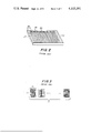
- FIG. 2 is a perspective view of a thermal printer head on which is disposed exothermic printing elements
- FIG. 3 is a schematic representation of the printing method effected by the thermal printing head of FIG. 2;
- FIG. 4 is a circuit and block diagram of an electronic table calculator embodying the controlling method for thermal printers in accordance with the invention
- FIG. 5 is a circuit diagram of one embodiment of the pulse generation circuit in accordance with the invention.
- FIG. 6 is a graphical representation of the voltage-current characteristic of a varistor in accordance with the invention.
- FIG. 7 is a waveform diagram illustrating the controlling method for thermal printers in accordance with the invention.
- FIG. 8 is a schematic representation of a step motor utilized in a thermal printer
- FIG. 9 is a waveform diagram of a thermal printer in accordance with the invention incorporating the step motor of FIG. 8;
- FIG. 10 are graphical representations of the period-voltage characteristics and period-ratio of Joule heat characteristics of the pulse generation circuit of FIG. 5 and of a more ideal pulse generation circuit;
- FIG. 11 is a circuit diagram of a second embodiment of the pulse generation circuit in accordance with the invention.
- FIG. 12 is a graphical representation of the period-voltage characteristic of the pulse generation circuit of FIG. 11 with variations in temperature.
- FIG. 13 is a fragmentary perspective view of a thermal printing head incorporating a temperature-sensitive thermistor in accordance with the invention.
- a conventional thermal printer is depicted incorporated in an electronic table calculator. Both the calculator and thermal printer are driven by a conventional power source 1 which may take the form of a dry cell, a Ni-Cd battery or a rectified commercial alternating power source. Said power source produces a voltage V 1 which may vary as more particularly described below.
- a voltage regulator 2 is provided for producing a fixed voltage V 2 in response to the application of voltage V 1 thereto.
- the voltage regulator circuit 2 is of conventional design incorporating a power transistor 3. The output of voltage regulator 2 is applied to power the printing head of a thermal printer.
- the printing head includes an array of exothermic printing elements 34 each connected in series with a feed transistor 35, said series connection being connected to receive the voltage V 2 .
- the actual application of driving current to the respective exothermic printing elements is controlled by the gating of the respective transistors 35 by a printer control unit 40.
- the table electronic calculator includes an oscillator 36 which produces clock pulses which are applied to regulate the operation of a central processing unit 37 in which arithmetic and other functions are performed. Data is applied to the central processing unit by keyboard 42.
- the central processing unit is coupled to a read only memory 38 for performing the memory functions of the calculator.
- the duration of the pulses is governed by a flip-flop 39 which is, in turn, driven by oscillator 36 which determines the period thereof.
- flip-flop 39 determines the period of the pulses
- printer control unit 40 determines which of the exothermic elements are to be actuated as determined by the signal received from the central processing unit 37.
- the printer control unit also controls a paper feeder 41, paper feeder 41 and exothermic elements 34 generally being formed as a unit to define what is generally accepted to be the "thermal printer" 43.
- the signal input by keyboard 12 is operated on in the central processing unit 37 in conjunction with read only memory 38 to transmit a signal to printer control unit 40 representative of the characters to be printed.
- the printer control unit 40 controls the respective feed transistors 35 and paper feeder 41 to print the designated characters, numerals, and the like.
- the head consists of a substrate 21 formed of an insulator such as ceramics or glass on which exothermic elements 34 are disposed in a line pattern as more particularly described below.
- One side of each of the exothermic elements are connected in common to a common electric conductor 22 which is in turn connected to one end of the power source (voltage V 2 , by way of example).
- the other end of each of said exothermic printing elements is connected to a conductor 23 for connection to the collector of a feed transistor 35.
- the exothermic elements are arranged in groups 24 consisting of five adjacent exothermic elements, the respective groups being spaced from each other, each group being utilized to form a single character.
- oscillator 36 is formed of a circuit having a relatively stable frequency, which frequency is divided by flip-flop 9 to determine the conducting time of the respective exothermic printing elements 34.
- power source 1 is characterized by variations in voltage
- the voltage regulator is required in order to maintain constant heat capacity of the exothermic printing elements 34.
- the device is usually operated within the range of 1.5 volts to 1 volt per cell, so that if eight dry cells in series are utilized as a power source 1, the supply voltage V 1 may change from 12 volts to 8 volts.
- the predetermined voltage V 2 on the secondary side of the regulator must be selected at about 5 volts, a voltage less than the minimum voltage V 1 . Accordingly, the use of the voltage regulator 2 causes a waste in power, principally due to the losses at the collector of the power transistor 3. Such losses provide a material disadvantage where power sources of limited capacity, such as batteries are used. This becomes particularly significant where portable electronic calculators are provided. Further, if regulator 2 is damaged by an abnormality, the voltage applied to the exothermic elements 34 increases markedly, creating the possibility of burning and damage thereto. Further, where the thermal printer and electronic table calculator are manufactured by different entities, there is a lack of coordination between the conducting time as determined by oscillator 36 and flip-flop 39 and the supply voltage, causing unevenness of printing.
- FIG. 4 an electronic table calculator incorporating a thermal printer in accordance with the invention is depicted, like reference numerals having been applied to like elements in FIGS. 3 and 4.
- the voltage regulator 3 has been replaced by a pulse generator 32, the voltage output V 3 of power source 31 being applied directly across the series connection of exothermic printing elements 34 and feed transistors 35.
- pulse generator 32 is adapted to detect the voltage level V 3 of of power source 31 and to produce a pulse the width or period of which is representative of the applied voltage.
- pulse generator 32 controls the conducting time of exothermic printing elements 34 and serves as the clock pulse generator for printer control unit 40.
- the clock pulse for the central processing unit 37 is still provided by oscillator 36.
- Pulse generator 32 is in the nature of a free-running multivibrator with transistors 55 and 56 being alternately rendered conductive and non-conductive depending on the time constant of the respective RC circuit associated therewith. Specifically, the time constant ⁇ 1 determined by capacitor 52 and varistor 51 controls the operation of transistor 56 while the time constant ⁇ 2 represented by resistance 53 and capacitor 54 controls the operation of transistor 55. The transistors 55 and 56 are alternately turned ON and OFF in response to the respective gate voltages thereof as determined by the respective time constant. In this manner, the time constants determine the period of the pulse output of pulse generator 32.
- the voltage-current characteristic of varistor 51 is depicted, wherein E represents the applied voltage to the varistor and I represents the current flow.
- the varistor is characterized by a resistance which varies inversely to the applied voltage so that as the applied voltage increases, the resistance decreases.
- the voltage applied to the varistor is the voltage V 3 from the power source.
- the period of the output pulses decreases due to the operation of varistor 51 and the altering of the time constant controlling the operation of transistor 56.
- the period of the output pulses of pulse generator 32 increases.
- a further feature of the arrangement in accordance with the invention is the provision of a thermistor as part or all of resistors 51 or 53, which thermistor is characterized by a variation in resistance with temperature. Since thermal printers are generally affected by ambient temperature, a thermistor having a negative characteristic is utilized in combination with either the varistor 51 or fixed resistor 53 so that the period of the pulse output of pulse generator 32 is relatively short at high temperatures while the pulse width of the pulse output is relatively long at low temperatures. In this manner, the conducting time of the exothermic elements 34 is adjusted so as to obtain proper printing quality.
- Waveform a represents the output waveform of pulse generator 32, which oscillates at a period T which depends on the level of the applied voltage from the voltage source, and, if desired, on variations in ambient temperature.
- Waveform b represents the output of flip-flop 39, namely the output of pulse generator 32 divided by a predetermined amount to produce a suitable clock pulse for the printer control unit.
- Waveform c represents a printing order transmitted to the printer control unit 40 by the central processing unit 37, as in response to an entry in keyboard 42.
- Waveform d illustrates the printing head conduction controlling pulse which predetermines the conducting time of the respective exothemic elements 34 and the position thereof in a given cycle of operation.
- Waveform e represents the waveform of the signal applied to energize the paper feeder 41 intermediate respective energizations of the selected exothermic elements.
- the conducting time W d necessary to effect printing of the first line in the m ⁇ n matrix of FIG. 3 is determined by the printing head conduction controlling pulse 61.
- pulse 62 determines the time for the second line of the matrix while pulse 63 governs the conduction time for the third line.
- pulses are produced until the nth line has been printed. At this time, printing of a given character has been effected.
- the period during which the power source of the paper feeder is driven is determined by the conducting time W e , which also determines the period during the cycle that paper feed is effected.
- the power source for a paper feeder is either a plunger, in the nature of a solenoid, or a step motor. In the arrangement of FIG.
- the printing head conduction controlling pulses as represented by waveform d and the paper feeder power source conduction controlling pulses represented by waveform e are both in synchronism with the output of pulse generator 32 as represented by waveform a of FIG. 7. Accordingly, not only does conduction time but printing speed varies with changes in voltage.
- the step motor utilized to drive a paper feeder is schematically depicted.
- the step motor is provided with a rotor 65 and driving coils 66 and 67 of conventional design, said driving coils being provided with center taps to define coils of four phases A, B, C and D.
- the rotor 65 is rotated at a fixed rotational angle by successively rendering the four coil phases conductive in the direction designated by arrows 68, so that the four coil phases are rendered conductive in the following order: A, B, C, D.
- Waveform f represents the output waveform of a pulse generator 32 having a period T.
- Waveform g represents the waveform of the printing head conduction controlling pulses which control the period of conduction of the exothermic elements 34.
- Waveforms h represent the respective conduction controlling pulses of the step motor, the respective signals applied to each of the phases A, B, C and D being separately identified, each of the phase conduction controlling pulses being of a width W h .
- the number of phase conduction control pulses applied to the step motor of the paper feeder depends on the amount of paper advance required between printing head conduction controlling pulses.
- the timing chart of FIG. 7 is more closely related to the timing chart of a plunger actuated paper feeder.
- the conducting time of the driving signal to the paper feeding plunger or step motor is fixed.
- the conducting time of the driving signals of the power supply of the paper feeder varies as the supply voltage changes. This is important since, in general, the plungers and step motors are characterized by the property that the response speed is high if the supply voltage is high.
- the plungers and step motors are characterized by the property that the response speed is high if the supply voltage is high.
- almost all of the electric energy is lost as heat dissipation in the power source (plunger or step motor) even if the conducting time is expanded beyond the fixed time.
- the failure to adequately dissipate the excessive heat generated in the step motor, plunger or other power source may cause the apparatus to burn or otherwise be damaged due to the rise in temperature upon the application of high voltages.
- This defect is avoided by the arrangement in accordance with the invention since the conducting time of the driving signal to the power source of the paper feeder varies with the supply voltage, thereby limiting the temperature rise occasioned in such power sources. In this manner, high reliability and security can be achieved.
- the conducting time of the driving signal to the paper feeder is relatively short at high voltages and relatively long at low voltages, an arrangement which also contributes to the efficient use of the available power to permit long-term driving of the thermal printer at low power consumption.
- points p and q are arbitrary points selected for the purposes of illustration.
- the current values at said points are I p and I q respectively and the voltage values at said points are E p and E q respectively.
- the characteristic of varistor 51 may generally be expressed by the following:
- K and ⁇ are constants.
- ⁇ may be expressed as follows, utilizing the above-defined current and voltage values at the arbitrary points p and q:
- the varistor is characterized by a ⁇ of 0.3 ⁇ 0.38 and the supply voltage is, for example, about 24 volts
- the relationship between the period T and the voltage V of the pulse generation circuit of FIG. 5 is represented by the characteristic curve 71 depicted in FIG. 10. This characteristic curve varies slightly due to the variation of the capacitor.
- the central value of the input voltages applied to the pulse generator and thermal printer 43 may be taken as V r , the point r on the characteristic curve 71 at which such voltage occurs corresponding to a period T r .
- the Joule heat J may be expressed as follows:
- a second arbitrary point on characteristic curve 71 of FIG. 10 is selected to be S
- the Joule heat at that point is J S
- the Joule heat at point r is J r .
- the relation J S /J r is depicted by line 72 in FIG. 10.
- Line 72 is essentially straight.
- Causing the conducting time of the exothermic elements 34 to change along characteristic curve 71 is based on the assumption that a uniform thermal capacity is applied and that the characters and symbols are thus printed with uniform printing quality. However, in actual printing, experience has shown that the printed character is darker at voltages higher than V r and lighter at voltages lower than V r .
- the embodiment of the pulse generator 32' depicted satisfies the requirements of characteristic curve 74 of FIG. 10.
- the circuit is characterized by a free-running multivibrator having a varistor 81 and capacitor 82 controlling the gate of transistor 86 and a variable resistor 83 and a capacitor 84 controlling the gate of transistor 85.
- the free-running multivibrator circuit of FIG. 11 operates in the same manner as the circuit of FIG. 5.
- Variable resistor 83 permits selective adjustment of the conduction period of the exothermic printing elements.
- the voltage of the voltage source is not applied directly to the free-running multivibrator, but rather, the voltage V 3 is applied through a constant voltage element, namely Zener diode 89 and a resistance element 90, said Zener diode and resistance element 90 being connected in series so that a voltage V 4 appears across the free-running multivibrator.
- the output of the free-running multivibrator is applied to a transistor 87 which serves to shape the waveform of the output of the multivibrator to apply said output to terminal 88.
- Resistance element 90 is depicted as consisting of the parallel combination of a fixed resistor 91 and a thermistor 92. However, in accordance with the invention, a thermistor may be used alone, the thermistor may be placed in series with the fixed resistor or, if temperature compensation is not required, resistance element 90 may be eliminated completely.
- the pulse generation circuit of FIG. 5 is characterized by a rate of change of the period of the output pulse signal determined by the rate of change of the applied voltage.
- the circuit of FIG. 11 is characterized by the characteristic curve 74. This is achieved by the insertion of Zener diode 89 intermediate voltage source V 3 and the free-running multivibrator (the point at which the voltage is V 4 ). The provision of the Zener diode 89 increases the rate of change of the voltage applied to the free-running multivibrator.
- the rate of change ⁇ 1 of the voltage may be expressed as follows:
- the rate of change ⁇ 1 is higher than the rate of change ⁇ 2 .
- the rate of change of the voltage is high, so that the rate of change of the period of the pulse generation circuit becomes high, so that the characteristic curve 71 which characterizes FIG. 5 is displaced in the direction of the characteristic curve 74 of FIG. 10.
- the rate of change of the period can be increased by raising the voltage V z of the Zener diode.
- a Zener diode may be utilized as the constant voltage element, but plural diodes for rectification connected in the forward direction may also serve as the constant voltage element.
- the value of the Zener diodes V z and the resistance of resistance 90 are selected to provide the desired characteristic curve for achieving the beneficial results in accordance with the invention.
- Curve 74 represents the characteristic curve of period versus voltage at a normal temperature.
- Curve 101 illustrates the displacement of the characteristic curve when the ambient temperature is about 50° C.
- curve 102 represents the characteristic curve when the ambient temperature is below about 0° C.
- V r the point r on characteristic curve 74 transfers to point t on curve 101 and point u on curve 102.
- the conducting time of the exothermic printing element changes in response to temperature such that the conducting time is decreased at high ambient temperatures and increased at low ambient temperatures. In this manner, stable printing quality can be obtained.
- resistance element 90 including thermistor 92 can be incorporated in resistor 83. It is also noted that, as illustrated in FIG. 13, thermistor 92 may be mounted on the substrate 21 of the thermal printing head so as to detect the temperature of the substrate to insure accurate temperature compensation in the actuation of the exothermic printing elements 34. The thermistor 92 may be connected to the circuit of FIG. 11 by means of conductors 103.
- the method and apparatus in accordance with the invention produce stable printing quality despite changes in the voltage output of the power source and changes in ambient temperature.
- the apparatus and method in accordance with the invention permits the use of thermal printing heads characterized by a wide variation in resistance value, the variations being absorbed by adjusting the pulse width or period of the output signal of pulse generator 32 (or 32') at the reference or central voltage V r according to the average value of the resistance of the exothermic element 34, so as to readily provide a thermal printer with uniform printing quality.
- the flip-flop 39 controlled by the output of pulse generator 32 is depicted as a separate element for purposes of explanation, said flip-flop is generally contained within the printer control unit 40. It is also common that the central processing unit 37 and the printer control unit 40 are formed in a unitary integrated circuit chip using large scale integration (LSI) techniques as well known in the art. Oscillator 36 may likewise be included in the LSI chips. In fact, even pulse generator circuit 32 can be incorporated in the chip of central processing unit 37 by selecting a material for the varistor which can be incorporated in an integrated circuit.
- LSI large scale integration
- thermal printer in accordance with the invention is equally applicable to other electronic apparatus incorporating thermal printers.
Abstract
A method and apparatus is provided for controlling the period or pulse width of pulses applied to exothermic printing elements of a thermal printer to effect printing. Control of the period or pulse width is in response to variations in applied voltage and ambient temperature. A pulse generator for this purpose may include such elements as a varistor, a constant voltage element and a thermistor.
Description
Generally speaking, this invention relates to thermal printers characterized by having exothermic printing elements driven by pulses of current which heat the exothermic elements to effect printing. In the art, such conventional thermal printing units are provided with a central processing unit which performs calculations and other functions and a printer control unit which controls the application of pulses to the exothermal printing elements in response to the signals received from the central processing unit. Generally, in the art, timing for clocking the central processing unit and for controlling the frequency and period of the printing pulses is controlled by a single oscillator. Since such thermal printers are frequently used in conjunction with battery-driven devices, and since the voltage of battery voltage sources varies with time, it was necessary to provide voltage regulator circuitry for stabilizing the voltage applied to the exothermic elements to effect printing. Voltage stabilization is generally selected at a level below the minimum voltage to which the battery may fall, thereby not efficiently using the full power available to the device.
Further, if the voltage regulator is damaged, a higher voltage than the voltage for which the exothermic printing elements are designed is applied to such exothermic printing elements, consequently resulting in the burning and damaging thereof. For this reason, the conventional thermal printers suffered from inferior reliability.
A further difficulty arises from the fact that the prior art thermal printers were frequently manufactured by entities different from the manufacturers of the electronic table calculators to which they were to be joined and were adapted to operate at different predetermined applied voltages, making proper operation of the prior art thermal printers more difficult and more expensive. A further difficulty in thermal printers is unevenness of printing due to variations in operating temperature due to variations in ambient temperature.
The foregoing difficulties in the prior art are avoided by providing a thermal printer wherein the pulse width of the signal applied to the exothermic printing elements is controlled in response to input voltage and ambient temperature.
Generally speaking, in accordance with the invention, a thermal printer is provided having exothermal printing elements adapted to be energized in response to pulses of current applied thereto. Control circuit means is provided for controlling the width of the driving pulses applied to said exothermic driving elements. Said control circuit means may consist of a pulse generation circuit including means for varying the period of the pulses produced thereby in response to the voltage applied thereto. Said pulse generation circuit may include a free-running multivibrator having a varistor in one RC circuit thereof. The thermal printer includes a printer control unit for selectively applying driving pulses to said exothermic printing element, said pulse generation circuit being coupled to control the pulse width of said driving pulses.
Said pulse generation circuit may also include means responsive to variations in ambient temperature for adjusting the pulse width in response to such changes in ambient temperature. Said temperature sensitive means may include thermistor means mounted on the base plate supporting said exothermic printing elements.
Said supply voltage may be applied to said pulse generation circuit through a constant voltage element and said thermistor means may be positioned intermediate said constant voltage element and said pulse generation circuit.
Accordingly, it is an object of this invention to provide a method and apparatus for obtaining stable print quality in a thermal printer despite variations in supply voltage and ambient temperature.
Another object of the invention is to provide a pulse generation circuit which can vary the driving pulse applied to the exothermic printing elements of a thermal printer in response to variations in supply voltage and ambient temperature.
A further object of the invention is to provide a circuit for protecting an exothermic printing element from abnormally high voltages.
Still a further object of the invention is to provide a method and apparatus for controlling a thermal printer which permits operation with low power consumption yet maximizes the efficiency of use of the available supply voltage.
Still other objects and advantages of the invention will in part be obvious and will in part be apparent from the specification and drawings.
The invention accordingly comprises the several steps and the relation of one or more of such steps with respect to each of the others, and the apparatus embodying features of construction, combinations of elements and arrangement of parts which are adapted to effect such steps, all as exemplified in the following detailed disclosure, and the scope of the invention will be indicated in the claims.
For a fuller understanding of the invention, reference is had to the following description taken in connection with the accompanying drawings, in which:
FIG. 1 is a circuit and block diagram of an electronic table calculator incorporating the voltage regulation arrangement for thermal printers of the prior art;
FIG. 2 is a perspective view of a thermal printer head on which is disposed exothermic printing elements;
FIG. 3 is a schematic representation of the printing method effected by the thermal printing head of FIG. 2;
FIG. 4 is a circuit and block diagram of an electronic table calculator embodying the controlling method for thermal printers in accordance with the invention;
FIG. 5 is a circuit diagram of one embodiment of the pulse generation circuit in accordance with the invention;
FIG. 6 is a graphical representation of the voltage-current characteristic of a varistor in accordance with the invention;
FIG. 7 is a waveform diagram illustrating the controlling method for thermal printers in accordance with the invention;
FIG. 8 is a schematic representation of a step motor utilized in a thermal printer;
FIG. 9 is a waveform diagram of a thermal printer in accordance with the invention incorporating the step motor of FIG. 8;
FIG. 10 are graphical representations of the period-voltage characteristics and period-ratio of Joule heat characteristics of the pulse generation circuit of FIG. 5 and of a more ideal pulse generation circuit;
FIG. 11 is a circuit diagram of a second embodiment of the pulse generation circuit in accordance with the invention;
FIG. 12 is a graphical representation of the period-voltage characteristic of the pulse generation circuit of FIG. 11 with variations in temperature; and
FIG. 13 is a fragmentary perspective view of a thermal printing head incorporating a temperature-sensitive thermistor in accordance with the invention.
Referring now to FIG. 1, a conventional thermal printer is depicted incorporated in an electronic table calculator. Both the calculator and thermal printer are driven by a conventional power source 1 which may take the form of a dry cell, a Ni-Cd battery or a rectified commercial alternating power source. Said power source produces a voltage V1 which may vary as more particularly described below. In order to avoid the effect of such variations in voltage source, a voltage regulator 2 is provided for producing a fixed voltage V2 in response to the application of voltage V1 thereto. The voltage regulator circuit 2 is of conventional design incorporating a power transistor 3. The output of voltage regulator 2 is applied to power the printing head of a thermal printer. Specifically, the printing head includes an array of exothermic printing elements 34 each connected in series with a feed transistor 35, said series connection being connected to receive the voltage V2. The actual application of driving current to the respective exothermic printing elements is controlled by the gating of the respective transistors 35 by a printer control unit 40. The table electronic calculator includes an oscillator 36 which produces clock pulses which are applied to regulate the operation of a central processing unit 37 in which arithmetic and other functions are performed. Data is applied to the central processing unit by keyboard 42. The central processing unit is coupled to a read only memory 38 for performing the memory functions of the calculator. Since the exothermic elements are driven by pulses of current, the duration of the pulses, namely the duration of the signal applied to the respective gates of transistors 35, is governed by a flip-flop 39 which is, in turn, driven by oscillator 36 which determines the period thereof. Thus, flip-flop 39 determines the period of the pulses and printer control unit 40 determines which of the exothermic elements are to be actuated as determined by the signal received from the central processing unit 37. The printer control unit also controls a paper feeder 41, paper feeder 41 and exothermic elements 34 generally being formed as a unit to define what is generally accepted to be the "thermal printer" 43.
In operation, the signal input by keyboard 12 is operated on in the central processing unit 37 in conjunction with read only memory 38 to transmit a signal to printer control unit 40 representative of the characters to be printed. The printer control unit 40 controls the respective feed transistors 35 and paper feeder 41 to print the designated characters, numerals, and the like.
Referring to FIG. 2, one embodiment of a thermal printing head is depicted. The head consists of a substrate 21 formed of an insulator such as ceramics or glass on which exothermic elements 34 are disposed in a line pattern as more particularly described below. One side of each of the exothermic elements are connected in common to a common electric conductor 22 which is in turn connected to one end of the power source (voltage V2, by way of example). The other end of each of said exothermic printing elements is connected to a conductor 23 for connection to the collector of a feed transistor 35. The exothermic elements are arranged in groups 24 consisting of five adjacent exothermic elements, the respective groups being spaced from each other, each group being utilized to form a single character. The method of forming characters is illustrated in connection with FIG. 3 wherein l characters are produced side-by-side by the thermal printer. Each character is defined by a matrix m wide and n small. Where l figures are required, the number of exothermic elements required are m × l. In the case of the print head of FIG. 2, m = 5 and l = 8 so that 40 exothermic elements are necessary. In the embodiments of FIG. 3, n = 7 so that a seven-step operation is required to print characters in a single line using the print head of FIG. 2, each step requiring an advance of the paper feeder 41. It should be noted that while a 5 × 7 matrix is depicted, the arrangement in accordance with the invention can apply equally to other forms of printing matrixes including seven-bar displays and the like.
In the circuit of FIG. 1, oscillator 36 is formed of a circuit having a relatively stable frequency, which frequency is divided by flip-flop 9 to determine the conducting time of the respective exothermic printing elements 34. Where power source 1 is characterized by variations in voltage, as where a dry cell is used as a power source, the voltage regulator is required in order to maintain constant heat capacity of the exothermic printing elements 34. By way of example, where dry cells are used, the device is usually operated within the range of 1.5 volts to 1 volt per cell, so that if eight dry cells in series are utilized as a power source 1, the supply voltage V1 may change from 12 volts to 8 volts.
In recognition of the foregoing voltage variations, the predetermined voltage V2 on the secondary side of the regulator must be selected at about 5 volts, a voltage less than the minimum voltage V1. Accordingly, the use of the voltage regulator 2 causes a waste in power, principally due to the losses at the collector of the power transistor 3. Such losses provide a material disadvantage where power sources of limited capacity, such as batteries are used. This becomes particularly significant where portable electronic calculators are provided. Further, if regulator 2 is damaged by an abnormality, the voltage applied to the exothermic elements 34 increases markedly, creating the possibility of burning and damage thereto. Further, where the thermal printer and electronic table calculator are manufactured by different entities, there is a lack of coordination between the conducting time as determined by oscillator 36 and flip-flop 39 and the supply voltage, causing unevenness of printing.
Referring now to FIG. 4, an electronic table calculator incorporating a thermal printer in accordance with the invention is depicted, like reference numerals having been applied to like elements in FIGS. 3 and 4. In the circuit of FIG. 4, the voltage regulator 3 has been replaced by a pulse generator 32, the voltage output V3 of power source 31 being applied directly across the series connection of exothermic printing elements 34 and feed transistors 35. As more particularly discussed below, pulse generator 32 is adapted to detect the voltage level V3 of of power source 31 and to produce a pulse the width or period of which is representative of the applied voltage. The pulse output of pulse generator 32 is applied to control flip-flop 39, which in turn regulates the width of the driving pulses applied to the respective gates of the transistors 35 to effect energizing of the exothermic elements to effect printing. Accordingly, pulse generator 32 controls the conducting time of exothermic printing elements 34 and serves as the clock pulse generator for printer control unit 40. The clock pulse for the central processing unit 37 is still provided by oscillator 36.
Referring now to FIG. 5, one embodiment of the pulse generator 32 is depicted. Pulse generator 32 is in the nature of a free-running multivibrator with transistors 55 and 56 being alternately rendered conductive and non-conductive depending on the time constant of the respective RC circuit associated therewith. Specifically, the time constant τ1 determined by capacitor 52 and varistor 51 controls the operation of transistor 56 while the time constant τ2 represented by resistance 53 and capacitor 54 controls the operation of transistor 55. The transistors 55 and 56 are alternately turned ON and OFF in response to the respective gate voltages thereof as determined by the respective time constant. In this manner, the time constants determine the period of the pulse output of pulse generator 32.
Referring to FIG. 6, the voltage-current characteristic of varistor 51 is depicted, wherein E represents the applied voltage to the varistor and I represents the current flow. The varistor is characterized by a resistance which varies inversely to the applied voltage so that as the applied voltage increases, the resistance decreases. In the case of the circuit of FIG. 5, the voltage applied to the varistor is the voltage V3 from the power source. As the power source voltage increases, the period of the output pulses decreases due to the operation of varistor 51 and the altering of the time constant controlling the operation of transistor 56. Similarly, as the voltage of the power source decreases, the period of the output pulses of pulse generator 32 increases.
A further feature of the arrangement in accordance with the invention is the provision of a thermistor as part or all of resistors 51 or 53, which thermistor is characterized by a variation in resistance with temperature. Since thermal printers are generally affected by ambient temperature, a thermistor having a negative characteristic is utilized in combination with either the varistor 51 or fixed resistor 53 so that the period of the pulse output of pulse generator 32 is relatively short at high temperatures while the pulse width of the pulse output is relatively long at low temperatures. In this manner, the conducting time of the exothermic elements 34 is adjusted so as to obtain proper printing quality.
Referring now to FIG. 7, a timing chart for the thermal printer 43 of the electronic table calculator of FIG. 4 is depicted. Waveform a represents the output waveform of pulse generator 32, which oscillates at a period T which depends on the level of the applied voltage from the voltage source, and, if desired, on variations in ambient temperature. Waveform b represents the output of flip-flop 39, namely the output of pulse generator 32 divided by a predetermined amount to produce a suitable clock pulse for the printer control unit. Waveform c represents a printing order transmitted to the printer control unit 40 by the central processing unit 37, as in response to an entry in keyboard 42. Waveform d illustrates the printing head conduction controlling pulse which predetermines the conducting time of the respective exothemic elements 34 and the position thereof in a given cycle of operation. Waveform e represents the waveform of the signal applied to energize the paper feeder 41 intermediate respective energizations of the selected exothermic elements.
The conducting time Wd necessary to effect printing of the first line in the m × n matrix of FIG. 3 is determined by the printing head conduction controlling pulse 61. Similarly, pulse 62 determines the time for the second line of the matrix while pulse 63 governs the conduction time for the third line. In like manner, pulses are produced until the nth line has been printed. At this time, printing of a given character has been effected. The period during which the power source of the paper feeder is driven is determined by the conducting time We, which also determines the period during the cycle that paper feed is effected. In general, the power source for a paper feeder is either a plunger, in the nature of a solenoid, or a step motor. In the arrangement of FIG. 7, the printing head conduction controlling pulses as represented by waveform d and the paper feeder power source conduction controlling pulses represented by waveform e are both in synchronism with the output of pulse generator 32 as represented by waveform a of FIG. 7. Accordingly, not only does conduction time but printing speed varies with changes in voltage.
Referring to FIG. 8, one embodiment of a step motor utilized to drive a paper feeder is schematically depicted. In this embodiment, the step motor is provided with a rotor 65 and driving coils 66 and 67 of conventional design, said driving coils being provided with center taps to define coils of four phases A, B, C and D. The rotor 65 is rotated at a fixed rotational angle by successively rendering the four coil phases conductive in the direction designated by arrows 68, so that the four coil phases are rendered conductive in the following order: A, B, C, D.
Referring to FIG. 9, a timing chart for driving a step motor embodiment of the type of FIG. 8 is depicted. Waveform f represents the output waveform of a pulse generator 32 having a period T. Waveform g represents the waveform of the printing head conduction controlling pulses which control the period of conduction of the exothermic elements 34. Waveforms h represent the respective conduction controlling pulses of the step motor, the respective signals applied to each of the phases A, B, C and D being separately identified, each of the phase conduction controlling pulses being of a width Wh. The number of phase conduction control pulses applied to the step motor of the paper feeder depends on the amount of paper advance required between printing head conduction controlling pulses. In this connection, it is noted that the timing chart of FIG. 7 is more closely related to the timing chart of a plunger actuated paper feeder.
In conventional voltage controlling arrangements for thermal printers, the conducting time of the driving signal to the paper feeding plunger or step motor is fixed. However, in the arrangement in accordance with the invention, the conducting time of the driving signals of the power supply of the paper feeder varies as the supply voltage changes. This is important since, in general, the plungers and step motors are characterized by the property that the response speed is high if the supply voltage is high. However, in the case of a high voltage, almost all of the electric energy is lost as heat dissipation in the power source (plunger or step motor) even if the conducting time is expanded beyond the fixed time. For this reason, in conventional thermal printers, the failure to adequately dissipate the excessive heat generated in the step motor, plunger or other power source may cause the apparatus to burn or otherwise be damaged due to the rise in temperature upon the application of high voltages. This defect is avoided by the arrangement in accordance with the invention since the conducting time of the driving signal to the power source of the paper feeder varies with the supply voltage, thereby limiting the temperature rise occasioned in such power sources. In this manner, high reliability and security can be achieved. Accordingly, in the arrangement in accordance with the invention, the conducting time of the driving signal to the paper feeder is relatively short at high voltages and relatively long at low voltages, an arrangement which also contributes to the efficient use of the available power to permit long-term driving of the thermal printer at low power consumption.
Referring again to FIG. 6, two points selected on the characteristic curve of the varistor, points p and q are arbitrary points selected for the purposes of illustration. The current values at said points are Ip and Iq respectively and the voltage values at said points are Ep and Eq respectively. The characteristic of varistor 51 may generally be expressed by the following:
E = K I β,
wherein K and β are constants. β may be expressed as follows, utilizing the above-defined current and voltage values at the arbitrary points p and q:
β = log (E.sub.q /E.sub.p)/log (I.sub.q /I.sub.p)
Where the varistor is characterized by a β of 0.3˜0.38 and the supply voltage is, for example, about 24 volts, the relationship between the period T and the voltage V of the pulse generation circuit of FIG. 5 is represented by the characteristic curve 71 depicted in FIG. 10. This characteristic curve varies slightly due to the variation of the capacitor. The central value of the input voltages applied to the pulse generator and thermal printer 43 may be taken as Vr, the point r on the characteristic curve 71 at which such voltage occurs corresponding to a period Tr.
Where the Joule heat at the time that an exothermic element 34 is rendered conductive is J, the resistance value of the exothermic element 34 is R34, the voltage applied across the exothermic element is V and the pulse width during which the exothermic element is conducting is Wd (in proportion to the period T), the Joule heat J may be expressed as follows:
(V.sup.2 × W.sub.d) / R.sub.34 = J
theoretically, if the Joule heat J is uniform, a fixed level of thermal heat is added to the exothermic element 34 and uniform printing quality results. Experimentation has revealed that the pulse generator circuit 32 of FIG. 5 permits the establishment of a uniform Joule heat through selection of the resistors and capacitors and the use of a varistor 51 having a β = 0.3˜0.38.
If a second arbitrary point on characteristic curve 71 of FIG. 10 is selected to be S, the Joule heat at that point is JS and the Joule heat at point r is Jr. The relation JS /Jr is depicted by line 72 in FIG. 10. Line 72 is essentially straight. Causing the conducting time of the exothermic elements 34 to change along characteristic curve 71 is based on the assumption that a uniform thermal capacity is applied and that the characters and symbols are thus printed with uniform printing quality. However, in actual printing, experience has shown that the printed character is darker at voltages higher than Vr and lighter at voltages lower than Vr. As a result of experimentation, it has been found that a period-ratio of Joule heat characteristic curve of the type represented by dashed line 73 in FIG. 10 avoids the foregoing difficulty of uneven printing quality. Line 73 is characterized by the ratio of Joule heat JS /Jr increasing as the period T increases.
It is believed that the uneven printing quality is caused by an increase in the escape of thermal heat to the substrate and ambience as the conducting period Wd increases. The relationship between the period T and the voltage V which satisfies the characteristic curve 73 is shown by the characteristic curve 74 in FIG. 10.
Referring now to FIG. 11, the embodiment of the pulse generator 32' depicted satisfies the requirements of characteristic curve 74 of FIG. 10. Specifically, the circuit is characterized by a free-running multivibrator having a varistor 81 and capacitor 82 controlling the gate of transistor 86 and a variable resistor 83 and a capacitor 84 controlling the gate of transistor 85. The free-running multivibrator circuit of FIG. 11 operates in the same manner as the circuit of FIG. 5. Variable resistor 83 permits selective adjustment of the conduction period of the exothermic printing elements. However, the voltage of the voltage source is not applied directly to the free-running multivibrator, but rather, the voltage V3 is applied through a constant voltage element, namely Zener diode 89 and a resistance element 90, said Zener diode and resistance element 90 being connected in series so that a voltage V4 appears across the free-running multivibrator. The output of the free-running multivibrator is applied to a transistor 87 which serves to shape the waveform of the output of the multivibrator to apply said output to terminal 88.
The pulse generation circuit of FIG. 5 is characterized by a rate of change of the period of the output pulse signal determined by the rate of change of the applied voltage. The circuit of FIG. 11 is characterized by the characteristic curve 74. This is achieved by the insertion of Zener diode 89 intermediate voltage source V3 and the free-running multivibrator (the point at which the voltage is V4). The provision of the Zener diode 89 increases the rate of change of the voltage applied to the free-running multivibrator. Thus, in the case where the center value of the voltage applied from the power source to the thermal printer 43 is Vr and the Zener voltage of the Zener diode is Vz, Vr being 20 volts, Vz being 10 volts, and further, the voltage of the power source changes to a level Vs equal to 18 volts, the rate of change ρ1 of the voltage may be expressed as follows:
ρ.sub.1 = (V.sub.r - V.sub.s)/(V.sub.r - V.sub.z) = (20 - 18)/(20 - 10) = 0.2
In the absence of the Zener diode, the rate of change ρ2 is expressed as follows:
ρ.sub.2 = (V.sub.r - V.sub.s)/V.sub.r = 0.1
From the above, it can be understood that the rate of change ρ1 is higher than the rate of change ρ2. When the rate of change of the voltage is high, the rate of change of the period of the pulse generation circuit becomes high, so that the characteristic curve 71 which characterizes FIG. 5 is displaced in the direction of the characteristic curve 74 of FIG. 10. From the foregoing it is also apparent that the rate of change of the period can be increased by raising the voltage Vz of the Zener diode. In general, a Zener diode may be utilized as the constant voltage element, but plural diodes for rectification connected in the forward direction may also serve as the constant voltage element. The value of the Zener diodes Vz and the resistance of resistance 90 are selected to provide the desired characteristic curve for achieving the beneficial results in accordance with the invention.
Referring now to FIG. 12, the temperature characteristic of the output signal of pulse generator circuit 32 of FIG. 11 is depicted. Curve 74 represents the characteristic curve of period versus voltage at a normal temperature. Curve 101 illustrates the displacement of the characteristic curve when the ambient temperature is about 50° C., while curve 102 represents the characteristic curve when the ambient temperature is below about 0° C. As is illustrated in FIG. 12, at a voltage Vr, the point r on characteristic curve 74 transfers to point t on curve 101 and point u on curve 102. In this manner, the conducting time of the exothermic printing element changes in response to temperature such that the conducting time is decreased at high ambient temperatures and increased at low ambient temperatures. In this manner, stable printing quality can be obtained.
It is noted that resistance element 90 including thermistor 92 can be incorporated in resistor 83. It is also noted that, as illustrated in FIG. 13, thermistor 92 may be mounted on the substrate 21 of the thermal printing head so as to detect the temperature of the substrate to insure accurate temperature compensation in the actuation of the exothermic printing elements 34. The thermistor 92 may be connected to the circuit of FIG. 11 by means of conductors 103.
The method and apparatus in accordance with the invention produce stable printing quality despite changes in the voltage output of the power source and changes in ambient temperature.
In this manner, restrictions imposed by prior art constructions on the accuracy of the clock pulse oscillator and on the accuracy of the power sources for electronic apparatus such as electronic table calculators is relieved, thereby increasing the marketability of the thermal printer in accordance with the invention. Further, the method and apparatus in accordance with the invention overcomes a further problem in the prior art arising from variations in the resistance value of the thermal head. This has resulted in rejection of some thermal printing heads due to incompatability with the associated circuitry. The apparatus and method in accordance with the invention permits the use of thermal printing heads characterized by a wide variation in resistance value, the variations being absorbed by adjusting the pulse width or period of the output signal of pulse generator 32 (or 32') at the reference or central voltage Vr according to the average value of the resistance of the exothermic element 34, so as to readily provide a thermal printer with uniform printing quality.
While in the embodiment of FIG. 4, the flip-flop 39 controlled by the output of pulse generator 32 is depicted as a separate element for purposes of explanation, said flip-flop is generally contained within the printer control unit 40. It is also common that the central processing unit 37 and the printer control unit 40 are formed in a unitary integrated circuit chip using large scale integration (LSI) techniques as well known in the art. Oscillator 36 may likewise be included in the LSI chips. In fact, even pulse generator circuit 32 can be incorporated in the chip of central processing unit 37 by selecting a material for the varistor which can be incorporated in an integrated circuit.
It is also noted that while the method and apparatus in accordance with the invention are depicted in connection with a thermal printer associated with an electronic table calculator, the thermal printer in accordance with the invention is equally applicable to other electronic apparatus incorporating thermal printers.
It will thus be seen that the objects set forth above, among those made apparent from the preceding description, are efficiently attained and, since certain changes may be made in carrying out the above method and in the constructions set forth without departing from the spirit and scope of the invention, it is intended that all matter contained in the above description and shown in the accompanying drawings shall be interpreted as illustrative and not in a limiting sense.
It is also to be understood that the following claims are intended to cover all of the generic and specific features of the invention herein described, and all statements of the scope of the invention which, as a matter of language, might be said to fall therebetween.
Claims (14)
1. An apparatus for controlling a thermal printer having a plurality of exothermic printing elements and adapted to be energized for printing by a current pulse produced in response to the output voltage of a power source, comprising driving circuit means for selectively applying driving pulses to said exothermic elements and control circuit means connected for detection of said power source output voltage and operatively coupled to said driving circuit means for adjusting the width of the driving pulses applied to said exothermic printing elements in response to the level of said power source output voltage so that the width of said driving pulses is increased in response to a decrease in said output voltage and is decreased in response to an increase in said output voltage, said control circuit means including a pulse generation circuit operably couplable to receive said power source output voltage for producing an oscillatory signal, said pulse generation circuit including voltage sensitive means including a varistor independent of said plurality of exothermic elements for adjusting the period of said oscillatory signal in response to the level of said output voltage so that the period of said oscillatory circuit is increased in response to a decrease in said output voltage and decreased in response to an increase in said output voltage, said oscillatory signal being applied to said driving circuit means for determining the width of said driving pulses.
2. The apparatus as recited in claim 1, wherein said control circuit means is adapted to detect the ambient temperature in the region of said exothermic printing elements and further adapted to adjust the width of said driving pulses in response to said detected ambient temperature so that the width of said driving pulses increases in response to a decrease in ambient temperature and decreases in response to an increase in ambient temperature.
3. The apparatus as recited in claim 2, including a substrate, said exothermic printing elements being mounted on said substrate, said control circuit means including a temperature sensitive means mounted on said substrate for detecting said ambient temperature.
4. The apparatus as recited in claim 1, wherein said control circuit means includes constant voltage element means and circuit means for detecting the difference voltage between said power source output voltage and a predetermined voltage of said constant voltage element means, said control circuit means being adapted to adjust the width of the driving pulses applied to said exothermic printing element in response to said output voltage by directly responding to said difference voltage so that the rate of change of the width of said driving pulses relative to the rate of change of said output voltage is increased relative to the rate of change in the width of said driving pulses which would result from adjustment of said driving pulse width directly in response to said output voltage.
5. The apparatus as recited in claim 4, wherein said constant voltage element means is a Zener diode.
6. A method for driving an exothermic printing element by means of a voltage source the output voltage of which may vary and wherein printing is effected on a heat sensitive paper by a paper advance means comprising providing a plurality of exothermic printing elements; selectively applying a pulse of current to selected of said exothermic printing elements sufficient to elevate the temperature of said selected exothermic printing elements to a printing temperature to define a predetermined character; detecting the output voltage of said power source; adjusting the pulse width of said driving current pulse in response to variations in the output voltage of said voltage source so as to narrow said pulse width in response to increases in output voltage and widen said pulse width in response to decreases in output voltage; selectively applying driving pulses to said paper advance means to effect advancement of said paper; and adjusting the pulse width of said paper advance driving pulses in response to said detected output voltage so that the width of the paper advance driving pulses is widened in response to a lowering of the output voltage of the power source and narrowed in response to an increase in the output voltage of the power source.
7. The method as recited in claim 6, including the further steps of detecting the ambient temperature in the region of said exothermic elements; and further adjusting said pulse width in response to said detected temperature so that said pulse width is narrowed in response to an increase in ambient temperature and widened in response to a decrease in ambient temperature.
8. The method as recited in claim 7, wherein said exothermic printing elements are mounted on a substrate, said ambient temperature being detected on said substrate.
9. The method as recited in claim 6, including the step of detecting a difference voltage representative of the difference between the output voltage of said power source and a predetermined voltage, said pulse width of said driving current pulse being adjusted in response to said difference voltage so that the pulse width will change a greater amount than if the pulse width is adjusted directly in response to said output voltage of said voltage source.
10. An apparatus for controlling a thermal printer having at least one exothermic printing element and adapted to be energized for printing by a current pulse produced in response to the output voltage of a power source, said thermal printer being adapted to effect printing on temperature sensitive paper and including paper advance means, comprising driving circuit means for selectively applying driving pulses to said exothermic elements; control circuit means connected for detection of said power source output voltage and operatively coupled to said driving circuit means for adjusting the width of the driving pulses applied to said exothermic printing elements in response to the level of said power source output voltage so that the width of said driving pulses is increased in response to a decrease in said output voltage and is decreased in response to an increase in said output voltage, said driving circuit means being further adapted to selectively apply driving pulses to said paper advance means to effect advancement thereof, said control circuit means being further adapted to adjust the width of said paper advance means driving pulses in response to the level of said output voltage of said power source so that the width of said paper advance means driving pulse is increased in response to a decrease in said output voltage and decreased in response to an increase in said output voltage.
11. An apparatus for controlling a thermal printer having at least one exothermic printing element and adapted to be energized for printing by a current pulse produced in response to the output voltage of a power source, comprising driving circuit means for selectively applying driving pulses to said exothermic elements and control circuit means connected for detection of said power source output voltage and operatively coupled to said driving circuit means for adjusting the width of the driving pulses applied to said exothermic printing elements in response to the level of said power source output voltage so that the width of said driving pulses is increased in response to a decrease in said output voltage and is decreased in response to an increase in said output voltage, said control circuit means including a pulse generation circuit operably couplable to receive said power source output voltage for producing an oscillatory signal, said pulse generation circuit including voltage sensitive means including a varistor for adjusting the period of said oscillatory signal in response to the level of said output voltage so that the period of said oscillatory circuit is increased in response to a decrease in said output voltage and decreased in response to an increase in said output voltage, said oscillatory signal being applied to said driving circuit means for determining the width of said driving pulses, said pulse generation circuit further including a free-running multivibrator circuit means having first and second R-C circuit means for controlling the period of oscillation thereof, one of said first and second R-C circuit means including said varistor.
12. The apparatus as recited in claim 11, including temperature sensitive resistive means the resistance of which varies with ambient temperature in the region of said exothermic printing element, one of said first and second R-C circuit means including said temperature sensitive resistive means so that the period of the oscillatory signal of said pulse generation circuit means increases in response to a decrease in detected ambient temperature and decreases in response to an increase in detected ambient temperature.
13. The apparatus as recited in claim 11, wherein said free-running multivibrator circuit means includes a pair of power terminals, said pulse generation circuit means including a constant voltage element means, said free-running multivibrator circuit means being connected in series with said constant voltage element means to receive said power source output voltage across said series connection, the period of said oscillatory circuit being adjusted in response to a difference voltage between said output voltage and the constant voltage of said constant voltage element means.
14. The apparatus as recited in claim 13, including temperature sensitive resistive means in said series connection and adapted to detect the ambient temperature in the region of said exothermic printing element, the period of said oscillatory signal of said pulse generation circuit means being adjusted by said temperature sensitive resistive means so that said period is increased in response to a decrease in ambient temperature and decreased in response to an increase in ambient temperature.
Applications Claiming Priority (2)
| Application Number | Priority Date | Filing Date | Title |
|---|---|---|---|
| JP12901975A JPS52141526A (en) | 1975-10-27 | 1975-10-27 | Voltage and temperature compensating control of thermal printer |
| JP50-129019 | 1975-10-27 |
Publications (1)
| Publication Number | Publication Date |
|---|---|
| US4113391A true US4113391A (en) | 1978-09-12 |
Family
ID=14999136
Family Applications (1)
| Application Number | Title | Priority Date | Filing Date |
|---|---|---|---|
| US05/736,046 Expired - Lifetime US4113391A (en) | 1975-10-27 | 1976-10-27 | Method for controlling voltage and providing temperature compensation in a thermal printer |
Country Status (2)
| Country | Link |
|---|---|
| US (1) | US4113391A (en) |
| JP (1) | JPS52141526A (en) |
Cited By (68)
| Publication number | Priority date | Publication date | Assignee | Title |
|---|---|---|---|---|
| US4203119A (en) * | 1978-09-05 | 1980-05-13 | Northern Telecom Limited | Thermal printers |
| EP0018762A1 (en) * | 1979-04-24 | 1980-11-12 | Oki Electric Industry Company, Limited | Thermal printing apparatus |
| US4268838A (en) * | 1978-07-18 | 1981-05-19 | Oki Electric Industry Co., Ltd. | Thermal recording system |
| EP0028957A1 (en) * | 1979-11-09 | 1981-05-20 | Thomson-Csf | Shade intensity reproducing device using a thermal print head, and thermal-printing system comprising such a device |
| US4305080A (en) * | 1979-07-18 | 1981-12-08 | International Business Machines Corporation | Compensating driver circuit for thermal print head |
| US4322733A (en) * | 1979-03-22 | 1982-03-30 | Fuji Xerox Co., Ltd. | Heat sensitive recording head drive device |
| US4330786A (en) * | 1979-06-18 | 1982-05-18 | Mitsubishi Denki Kabushiki Kaisha | Method of controlling thermally controlling a thermal printing head |
| DE3143785A1 (en) * | 1980-11-06 | 1982-06-03 | Sony Corp., Tokyo | METHOD AND CIRCUIT FOR CONTROLLING A PRINTER HAVING THERMAL PRESSURE BUTTONS |
| DE3143784A1 (en) * | 1980-11-05 | 1982-07-08 | Sony Corp., Tokyo | METHOD AND CIRCUIT ARRANGEMENT FOR CONTROLLING THE SUPPLY OR EXCITATION OF PRINT HEADS |
| US4350449A (en) * | 1980-06-23 | 1982-09-21 | International Business Machines Corporation | Resistive ribbon printing apparatus and method |
| DE3144368A1 (en) * | 1980-11-07 | 1982-09-30 | Hitachi, Ltd., Tokyo | CONTROL CIRCUIT FOR DETERMINING THE PRESSURE PULSE FOR THE HEADS OF THERMAL PRINTERS |
| US4360819A (en) * | 1980-03-12 | 1982-11-23 | Tokyo Shibaura Denki Kabushiki Kaisha | Thermal recording apparatus |
| US4366489A (en) * | 1980-02-06 | 1982-12-28 | Ricoh Company, Ltd. | Thermal recording apparatus |
| US4370666A (en) * | 1979-08-10 | 1983-01-25 | Canon Kabushiki Kaisha | Thermal head driving device |
| US4391535A (en) * | 1981-08-10 | 1983-07-05 | Intermec Corporation | Method and apparatus for controlling the area of a thermal print medium that is exposed by a thermal printer |
| FR2520532A1 (en) * | 1982-01-25 | 1983-07-29 | Sony Corp | THERMAL HEAD CONTROL DEVICE FOR THERMAL PRINTER |
| US4396923A (en) * | 1979-05-16 | 1983-08-02 | Canon Kabushiki Kaisha | Recording control apparatus |
| US4404567A (en) * | 1980-10-03 | 1983-09-13 | Ricoh Company, Ltd. | Printing head drive circuit for thermal printer |
| US4409600A (en) * | 1980-12-29 | 1983-10-11 | Epson Corporation | Thermal printer drive circuit |
| US4442342A (en) * | 1981-05-01 | 1984-04-10 | Sharp Kabushiki Kaisha | Thermal printer with print density control |
| US4462704A (en) * | 1981-12-04 | 1984-07-31 | Fuji Xerox Co., Ltd. | Thermal heat driving system |
| FR2547535A1 (en) * | 1983-04-14 | 1984-12-21 | Monarch Marking Systems Inc | THERMOGRAPHIC PRINTING DEVICE |
| FR2547556A1 (en) * | 1983-04-14 | 1984-12-21 | Monarch Marking Systems Inc | Labelling machine including a thermographic printing device |
| EP0132471A2 (en) * | 1983-07-23 | 1985-02-13 | Francotyp-Postalia GmbH | Franking machine |
| US4510507A (en) * | 1982-08-05 | 1985-04-09 | Canon Kabushiki Kaisha | Thermal recording apparatus |
| US4523203A (en) * | 1984-05-07 | 1985-06-11 | Honeywell Inc. | Grey scale thermal printer control system |
| US4540295A (en) * | 1983-12-06 | 1985-09-10 | Citizen Watch Co., Ltd. | Method for controlling the temperature of the printing head of an impact printer |
| US4543588A (en) * | 1982-07-17 | 1985-09-24 | Canon Kabushiki Kaisha | Dot printer |
| EP0163297A2 (en) * | 1984-05-30 | 1985-12-04 | Matsushita Electric Industrial Co., Ltd. | Thermal transfer sheet and method for fabricating same |
| US4558331A (en) * | 1984-05-07 | 1985-12-10 | Honeywell Inc. | Heating resistor shape in a thermal printhead |
| US4573059A (en) * | 1984-02-29 | 1986-02-25 | Mitsubishi Denki Kabushiki Kaisha | Ink donor sheet color detecting device |
| US4590488A (en) * | 1985-05-28 | 1986-05-20 | Astro-Med, Inc. | Circuit for controlling energization of thermal print head |
| US4594501A (en) * | 1980-10-09 | 1986-06-10 | Texas Instruments Incorporated | Pulse width modulation of printhead voltage |
| US4647233A (en) * | 1978-03-08 | 1987-03-03 | Canon Kabushiki Kaisha | Thermal printer |
| FR2586615A1 (en) * | 1985-09-02 | 1987-03-06 | Enertec | Device and method for feeding a thermal printing head |
| US4651166A (en) * | 1985-05-10 | 1987-03-17 | Ricoh Company, Ltd. | Temperature control device for head of thermal printer |
| EP0216684A2 (en) * | 1985-09-02 | 1987-04-01 | Schlumberger Industries | Apparatus and method for supplying a thermal-printing head |
| US4659416A (en) * | 1982-01-07 | 1987-04-21 | Ecupan Ab | Thermal bar code printer for label applicator |
| US4669897A (en) * | 1981-07-07 | 1987-06-02 | Canon Kabushiki Kaisha | Dot matrix printer capable of varying character size |
| US4714363A (en) * | 1984-05-18 | 1987-12-22 | Seiko Epson Corporation | Print control device for a dot matrix printer |
| US4755724A (en) * | 1985-08-17 | 1988-07-05 | Telefunken Electronic Gmbh | Method for periodic triggering of several radiation-emitting elements |
| US4758966A (en) * | 1986-05-05 | 1988-07-19 | Ncr Canada Ltd. - Ncr Canada Ltee | Thermal printing apparatus and method |
| US4797837A (en) * | 1986-04-24 | 1989-01-10 | Ncr Canada Ltd. - Ncr Canada Ltee | Method and apparatus for thermal printer temperature control |
| US4933535A (en) * | 1989-02-15 | 1990-06-12 | Harper-Wyman Company | Piecewise linear temperature controller utilizing pulse width modulation |
| US5046859A (en) * | 1988-06-17 | 1991-09-10 | Ricoh Company, Ltd. | Temperature measuring device and thermal head device having the same |
| US5087923A (en) * | 1990-05-25 | 1992-02-11 | Hewlett-Packard Company | Method of adjusting a strobe pulse for a thermal line array printer |
| US5105067A (en) * | 1989-09-08 | 1992-04-14 | Environwear, Inc. | Electronic control system and method for cold weather garment |
| US5191356A (en) * | 1986-07-18 | 1993-03-02 | Canon Kabushiki Kaisha | Tower conserving recording apparatus |
| FR2692839A1 (en) * | 1992-06-25 | 1993-12-31 | Sagem | Energy supply for thermal print head of facsimile machine - uses measurement of supply voltage to heating element on print head to determine duration of supply and thus temperature |
| US5432533A (en) * | 1986-07-18 | 1995-07-11 | Canon Kabushiki Kaisha | Recording method with control of head energization and recording medium conveyance power consumption |
| US5588092A (en) * | 1992-05-26 | 1996-12-24 | Matsushita Electric Industrial Co., Ltd. | Printer control circuit and the printer controlled thereby |
| US5683189A (en) * | 1986-12-27 | 1997-11-04 | Canon Kabushiki Kaisha | Thermal printer with erasing function using thinned heating energy generating patterns |
| US5745146A (en) * | 1994-02-15 | 1998-04-28 | Monarch Marking Systems, Inc. | Dynamic strobe compensation control for a barcode printer |
| US5788385A (en) * | 1991-09-19 | 1998-08-04 | Canon Kabushiki Kaisha | Serial recording system capable of varing resolution |
| US5890819A (en) * | 1992-10-29 | 1999-04-06 | Eastman Kodak Company | Thermal printer system and method for improved compensation of variations in operating parameters |
| US5902054A (en) * | 1996-01-31 | 1999-05-11 | Canon Kabushiki Kaisha | Energy saving image edging method and device |
| WO1999045745A1 (en) * | 1998-03-05 | 1999-09-10 | Fsi International, Inc. | Combination bake/chill apparatus incorporating low thermal mass, thermally conductive bakeplate |
| US6095700A (en) * | 1993-10-30 | 2000-08-01 | Asahi Kogaku Kogyo Kabushiki Kaisha | Battery operated thermal printer with means to optimize battery life |
| GB2356375A (en) * | 1999-11-22 | 2001-05-23 | Esselte Nv | Method of controlling a thermal print head |
| US20010052988A1 (en) * | 2000-06-16 | 2001-12-20 | Alps Electric Co., Ltd. | Method for driving paper-feeding stepping motor in thermal printer |
| US20020102837A1 (en) * | 1998-02-04 | 2002-08-01 | Ritzdorf Thomas L. | Method for filling recessed micro-structures with metallization in the production of a microelectronic device |
| US6471913B1 (en) | 2000-02-09 | 2002-10-29 | Semitool, Inc. | Method and apparatus for processing a microelectronic workpiece including an apparatus and method for executing a processing step at an elevated temperature |
| US6476838B1 (en) * | 1999-09-03 | 2002-11-05 | Oki Data America, Inc. | Method of driving a thermal print head |
| US6529686B2 (en) | 2001-06-06 | 2003-03-04 | Fsi International, Inc. | Heating member for combination heating and chilling apparatus, and methods |
| US20040057742A1 (en) * | 2002-09-19 | 2004-03-25 | Richtsmeier Dean J. | Imaging equipment acceleration apparatus and methods |
| US6780374B2 (en) | 2000-12-08 | 2004-08-24 | Semitool, Inc. | Method and apparatus for processing a microelectronic workpiece at an elevated temperature |
| US6784908B2 (en) * | 2000-11-16 | 2004-08-31 | Olympus Corporation | Printer |
| US7102763B2 (en) | 2000-07-08 | 2006-09-05 | Semitool, Inc. | Methods and apparatus for processing microelectronic workpieces using metrology |
Families Citing this family (4)
| Publication number | Priority date | Publication date | Assignee | Title |
|---|---|---|---|---|
| JPS5353223A (en) * | 1976-10-25 | 1978-05-15 | Epson Corp | Circuit for compensating voltage of thermal printer |
| JPS5653084A (en) * | 1979-10-08 | 1981-05-12 | Hitachi Ltd | Printer |
| JPS5827464A (en) * | 1981-08-11 | 1983-02-18 | Nippon Telegr & Teleph Corp <Ntt> | Controller for heat sensing recording |
| JPS60182148U (en) * | 1985-04-17 | 1985-12-03 | 富士通株式会社 | serial dot printer |
Citations (22)
| Publication number | Priority date | Publication date | Assignee | Title |
|---|---|---|---|---|
| US3577137A (en) * | 1968-12-31 | 1971-05-04 | Texas Instruments Inc | Temperature compensated electronic display |
| US3754278A (en) * | 1971-12-01 | 1973-08-21 | American Micro Syst | Thermal printing system |
| US3777116A (en) * | 1971-10-04 | 1973-12-04 | Olivetti & Co Spa | Thermographic printing arrangement |
| US3805022A (en) * | 1972-10-10 | 1974-04-16 | Texas Instruments Inc | Semiconducting threshold heaters |
| US3810192A (en) * | 1972-06-29 | 1974-05-07 | Copal Co Ltd | Thermosensitive line printer |
| US3813677A (en) * | 1972-02-23 | 1974-05-28 | Matsushita Electric Ind Co Ltd | Heat-sensitive record |
| US3820099A (en) * | 1972-04-17 | 1974-06-25 | Gen Motors Corp | Voltage detector |
| US3842243A (en) * | 1973-07-16 | 1974-10-15 | Solitech Inc | Temperature control system for proportional electric heating |
| US3845850A (en) * | 1973-02-22 | 1974-11-05 | Bowmar Instrument Corp | Thermal printer |
| US3874493A (en) * | 1972-11-06 | 1975-04-01 | Texas Instruments Inc | Electronic page printer |
| US3913091A (en) * | 1972-12-19 | 1975-10-14 | Suwa Seikosha Kk | Thermal sensitive printing head |
| US3917993A (en) * | 1972-10-31 | 1975-11-04 | Klein Schanzlin & Becker Ag | Bistable regulator having positive and negative feedback |
| US3921162A (en) * | 1972-04-06 | 1975-11-18 | Matsushita Electric Ind Co Ltd | Method of driving liquid crystal display device |
| US3934695A (en) * | 1974-09-23 | 1976-01-27 | Hewlett-Packard Company | Method and apparatus for enhancing and maintaining character quality in thermal printers |
| US3975742A (en) * | 1975-09-25 | 1976-08-17 | Honeywell Inc. | Thermal printing-anti-stick mechanism |
| US3975707A (en) * | 1970-04-13 | 1976-08-17 | Canon Kabushiki Kaisha | Device for controlling the density of printing characters |
| US3996581A (en) * | 1975-05-22 | 1976-12-07 | Sanders Associates, Inc. | Hard copy tone address paging system |
| US4004672A (en) * | 1974-02-22 | 1977-01-25 | Canon Kabushiki Kaisha | Printing control device |
| US4027761A (en) * | 1975-10-21 | 1977-06-07 | Ncr Corporation | Matrix print head impact energy control |
| US4030588A (en) * | 1972-06-19 | 1977-06-21 | Canon Kabushiki Kaisha | Printer |
| US4032925A (en) * | 1976-05-10 | 1977-06-28 | Northern Telecom Limited | Drive circuit for thermal printing array |
| US4038516A (en) * | 1975-02-19 | 1977-07-26 | Facit Aktiebolag | Thermal printing head |
-
1975
- 1975-10-27 JP JP12901975A patent/JPS52141526A/en active Pending
-
1976
- 1976-10-27 US US05/736,046 patent/US4113391A/en not_active Expired - Lifetime
Patent Citations (22)
| Publication number | Priority date | Publication date | Assignee | Title |
|---|---|---|---|---|
| US3577137A (en) * | 1968-12-31 | 1971-05-04 | Texas Instruments Inc | Temperature compensated electronic display |
| US3975707A (en) * | 1970-04-13 | 1976-08-17 | Canon Kabushiki Kaisha | Device for controlling the density of printing characters |
| US3777116A (en) * | 1971-10-04 | 1973-12-04 | Olivetti & Co Spa | Thermographic printing arrangement |
| US3754278A (en) * | 1971-12-01 | 1973-08-21 | American Micro Syst | Thermal printing system |
| US3813677A (en) * | 1972-02-23 | 1974-05-28 | Matsushita Electric Ind Co Ltd | Heat-sensitive record |
| US3921162A (en) * | 1972-04-06 | 1975-11-18 | Matsushita Electric Ind Co Ltd | Method of driving liquid crystal display device |
| US3820099A (en) * | 1972-04-17 | 1974-06-25 | Gen Motors Corp | Voltage detector |
| US4030588A (en) * | 1972-06-19 | 1977-06-21 | Canon Kabushiki Kaisha | Printer |
| US3810192A (en) * | 1972-06-29 | 1974-05-07 | Copal Co Ltd | Thermosensitive line printer |
| US3805022A (en) * | 1972-10-10 | 1974-04-16 | Texas Instruments Inc | Semiconducting threshold heaters |
| US3917993A (en) * | 1972-10-31 | 1975-11-04 | Klein Schanzlin & Becker Ag | Bistable regulator having positive and negative feedback |
| US3874493A (en) * | 1972-11-06 | 1975-04-01 | Texas Instruments Inc | Electronic page printer |
| US3913091A (en) * | 1972-12-19 | 1975-10-14 | Suwa Seikosha Kk | Thermal sensitive printing head |
| US3845850A (en) * | 1973-02-22 | 1974-11-05 | Bowmar Instrument Corp | Thermal printer |
| US3842243A (en) * | 1973-07-16 | 1974-10-15 | Solitech Inc | Temperature control system for proportional electric heating |
| US4004672A (en) * | 1974-02-22 | 1977-01-25 | Canon Kabushiki Kaisha | Printing control device |
| US3934695A (en) * | 1974-09-23 | 1976-01-27 | Hewlett-Packard Company | Method and apparatus for enhancing and maintaining character quality in thermal printers |
| US4038516A (en) * | 1975-02-19 | 1977-07-26 | Facit Aktiebolag | Thermal printing head |
| US3996581A (en) * | 1975-05-22 | 1976-12-07 | Sanders Associates, Inc. | Hard copy tone address paging system |
| US3975742A (en) * | 1975-09-25 | 1976-08-17 | Honeywell Inc. | Thermal printing-anti-stick mechanism |
| US4027761A (en) * | 1975-10-21 | 1977-06-07 | Ncr Corporation | Matrix print head impact energy control |
| US4032925A (en) * | 1976-05-10 | 1977-06-28 | Northern Telecom Limited | Drive circuit for thermal printing array |
Cited By (83)
| Publication number | Priority date | Publication date | Assignee | Title |
|---|---|---|---|---|
| US4647233A (en) * | 1978-03-08 | 1987-03-03 | Canon Kabushiki Kaisha | Thermal printer |
| US4268838A (en) * | 1978-07-18 | 1981-05-19 | Oki Electric Industry Co., Ltd. | Thermal recording system |
| US4203119A (en) * | 1978-09-05 | 1980-05-13 | Northern Telecom Limited | Thermal printers |
| US4322733A (en) * | 1979-03-22 | 1982-03-30 | Fuji Xerox Co., Ltd. | Heat sensitive recording head drive device |
| EP0018762A1 (en) * | 1979-04-24 | 1980-11-12 | Oki Electric Industry Company, Limited | Thermal printing apparatus |
| US4396923A (en) * | 1979-05-16 | 1983-08-02 | Canon Kabushiki Kaisha | Recording control apparatus |
| US4330786A (en) * | 1979-06-18 | 1982-05-18 | Mitsubishi Denki Kabushiki Kaisha | Method of controlling thermally controlling a thermal printing head |
| US4305080A (en) * | 1979-07-18 | 1981-12-08 | International Business Machines Corporation | Compensating driver circuit for thermal print head |
| US4370666A (en) * | 1979-08-10 | 1983-01-25 | Canon Kabushiki Kaisha | Thermal head driving device |
| EP0028957A1 (en) * | 1979-11-09 | 1981-05-20 | Thomson-Csf | Shade intensity reproducing device using a thermal print head, and thermal-printing system comprising such a device |
| US4335968A (en) * | 1979-11-09 | 1982-06-22 | Thomson-Csf | Tint restoring device employing a thermal printing head |
| FR2469841A1 (en) * | 1979-11-09 | 1981-05-22 | Thomson Csf | COLOR RETURN DEVICE USING A THERMAL PRINT HEAD AND THERMAL PRINT SYSTEM COMPRISING SUCH A DEVICE |
| US4366489A (en) * | 1980-02-06 | 1982-12-28 | Ricoh Company, Ltd. | Thermal recording apparatus |
| US4360819A (en) * | 1980-03-12 | 1982-11-23 | Tokyo Shibaura Denki Kabushiki Kaisha | Thermal recording apparatus |
| US4350449A (en) * | 1980-06-23 | 1982-09-21 | International Business Machines Corporation | Resistive ribbon printing apparatus and method |
| US4404567A (en) * | 1980-10-03 | 1983-09-13 | Ricoh Company, Ltd. | Printing head drive circuit for thermal printer |
| US4594501A (en) * | 1980-10-09 | 1986-06-10 | Texas Instruments Incorporated | Pulse width modulation of printhead voltage |
| DE3143784A1 (en) * | 1980-11-05 | 1982-07-08 | Sony Corp., Tokyo | METHOD AND CIRCUIT ARRANGEMENT FOR CONTROLLING THE SUPPLY OR EXCITATION OF PRINT HEADS |
| DE3143785A1 (en) * | 1980-11-06 | 1982-06-03 | Sony Corp., Tokyo | METHOD AND CIRCUIT FOR CONTROLLING A PRINTER HAVING THERMAL PRESSURE BUTTONS |
| DE3144368A1 (en) * | 1980-11-07 | 1982-09-30 | Hitachi, Ltd., Tokyo | CONTROL CIRCUIT FOR DETERMINING THE PRESSURE PULSE FOR THE HEADS OF THERMAL PRINTERS |
| US4409600A (en) * | 1980-12-29 | 1983-10-11 | Epson Corporation | Thermal printer drive circuit |
| US4442342A (en) * | 1981-05-01 | 1984-04-10 | Sharp Kabushiki Kaisha | Thermal printer with print density control |
| US4669897A (en) * | 1981-07-07 | 1987-06-02 | Canon Kabushiki Kaisha | Dot matrix printer capable of varying character size |
| US4391535A (en) * | 1981-08-10 | 1983-07-05 | Intermec Corporation | Method and apparatus for controlling the area of a thermal print medium that is exposed by a thermal printer |
| US4462704A (en) * | 1981-12-04 | 1984-07-31 | Fuji Xerox Co., Ltd. | Thermal heat driving system |
| US4659416A (en) * | 1982-01-07 | 1987-04-21 | Ecupan Ab | Thermal bar code printer for label applicator |
| FR2520532A1 (en) * | 1982-01-25 | 1983-07-29 | Sony Corp | THERMAL HEAD CONTROL DEVICE FOR THERMAL PRINTER |
| US4543588A (en) * | 1982-07-17 | 1985-09-24 | Canon Kabushiki Kaisha | Dot printer |
| US4510507A (en) * | 1982-08-05 | 1985-04-09 | Canon Kabushiki Kaisha | Thermal recording apparatus |
| FR2547556A1 (en) * | 1983-04-14 | 1984-12-21 | Monarch Marking Systems Inc | Labelling machine including a thermographic printing device |
| FR2547537A1 (en) * | 1983-04-14 | 1984-12-21 | Monarch Marking Systems Inc | THERMOGRAPHIC PRINTING DEVICE |
| FR2547535A1 (en) * | 1983-04-14 | 1984-12-21 | Monarch Marking Systems Inc | THERMOGRAPHIC PRINTING DEVICE |
| FR2547536A1 (en) * | 1983-04-14 | 1984-12-21 | Monarch Marking Systems Inc | THERMOGRAPHIC PRINTING DEVICE |
| EP0132471A3 (en) * | 1983-07-23 | 1986-10-01 | P A Consulting Services Limited | Franking machine |
| EP0132471A2 (en) * | 1983-07-23 | 1985-02-13 | Francotyp-Postalia GmbH | Franking machine |
| US4540295A (en) * | 1983-12-06 | 1985-09-10 | Citizen Watch Co., Ltd. | Method for controlling the temperature of the printing head of an impact printer |
| US4573059A (en) * | 1984-02-29 | 1986-02-25 | Mitsubishi Denki Kabushiki Kaisha | Ink donor sheet color detecting device |
| US4523203A (en) * | 1984-05-07 | 1985-06-11 | Honeywell Inc. | Grey scale thermal printer control system |
| US4558331A (en) * | 1984-05-07 | 1985-12-10 | Honeywell Inc. | Heating resistor shape in a thermal printhead |
| US4714363A (en) * | 1984-05-18 | 1987-12-22 | Seiko Epson Corporation | Print control device for a dot matrix printer |
| EP0163297A3 (en) * | 1984-05-30 | 1988-04-06 | Matsushita Electric Industrial Co., Ltd. | Thermal transfer sheet and method for fabricating same |
| US4819010A (en) * | 1984-05-30 | 1989-04-04 | Matsushita Electric Industrial Co., Ltd. | Thermal printer using a thermally transferable ink sheet |
| EP0163297A2 (en) * | 1984-05-30 | 1985-12-04 | Matsushita Electric Industrial Co., Ltd. | Thermal transfer sheet and method for fabricating same |
| US4651166A (en) * | 1985-05-10 | 1987-03-17 | Ricoh Company, Ltd. | Temperature control device for head of thermal printer |
| US4590488A (en) * | 1985-05-28 | 1986-05-20 | Astro-Med, Inc. | Circuit for controlling energization of thermal print head |
| US4755724A (en) * | 1985-08-17 | 1988-07-05 | Telefunken Electronic Gmbh | Method for periodic triggering of several radiation-emitting elements |
| FR2586615A1 (en) * | 1985-09-02 | 1987-03-06 | Enertec | Device and method for feeding a thermal printing head |
| EP0216684A3 (en) * | 1985-09-02 | 1987-08-05 | Schlumberger Industries | Apparatus and method for supplying a thermal-printing head |
| EP0216684A2 (en) * | 1985-09-02 | 1987-04-01 | Schlumberger Industries | Apparatus and method for supplying a thermal-printing head |
| US4737800A (en) * | 1985-09-02 | 1988-04-12 | Enertec | Electrical supply for a thermal printing head |
| US4797837A (en) * | 1986-04-24 | 1989-01-10 | Ncr Canada Ltd. - Ncr Canada Ltee | Method and apparatus for thermal printer temperature control |
| US4758966A (en) * | 1986-05-05 | 1988-07-19 | Ncr Canada Ltd. - Ncr Canada Ltee | Thermal printing apparatus and method |
| US5191356A (en) * | 1986-07-18 | 1993-03-02 | Canon Kabushiki Kaisha | Tower conserving recording apparatus |
| US5432533A (en) * | 1986-07-18 | 1995-07-11 | Canon Kabushiki Kaisha | Recording method with control of head energization and recording medium conveyance power consumption |
| US5683189A (en) * | 1986-12-27 | 1997-11-04 | Canon Kabushiki Kaisha | Thermal printer with erasing function using thinned heating energy generating patterns |
| US5046859A (en) * | 1988-06-17 | 1991-09-10 | Ricoh Company, Ltd. | Temperature measuring device and thermal head device having the same |
| US4933535A (en) * | 1989-02-15 | 1990-06-12 | Harper-Wyman Company | Piecewise linear temperature controller utilizing pulse width modulation |
| US5105067A (en) * | 1989-09-08 | 1992-04-14 | Environwear, Inc. | Electronic control system and method for cold weather garment |
| US5087923A (en) * | 1990-05-25 | 1992-02-11 | Hewlett-Packard Company | Method of adjusting a strobe pulse for a thermal line array printer |
| US5788385A (en) * | 1991-09-19 | 1998-08-04 | Canon Kabushiki Kaisha | Serial recording system capable of varing resolution |
| US5588092A (en) * | 1992-05-26 | 1996-12-24 | Matsushita Electric Industrial Co., Ltd. | Printer control circuit and the printer controlled thereby |
| FR2692839A1 (en) * | 1992-06-25 | 1993-12-31 | Sagem | Energy supply for thermal print head of facsimile machine - uses measurement of supply voltage to heating element on print head to determine duration of supply and thus temperature |
| US5890819A (en) * | 1992-10-29 | 1999-04-06 | Eastman Kodak Company | Thermal printer system and method for improved compensation of variations in operating parameters |
| US6095700A (en) * | 1993-10-30 | 2000-08-01 | Asahi Kogaku Kogyo Kabushiki Kaisha | Battery operated thermal printer with means to optimize battery life |
| US5745146A (en) * | 1994-02-15 | 1998-04-28 | Monarch Marking Systems, Inc. | Dynamic strobe compensation control for a barcode printer |
| US5902054A (en) * | 1996-01-31 | 1999-05-11 | Canon Kabushiki Kaisha | Energy saving image edging method and device |
| US20020102837A1 (en) * | 1998-02-04 | 2002-08-01 | Ritzdorf Thomas L. | Method for filling recessed micro-structures with metallization in the production of a microelectronic device |
| US6753251B2 (en) | 1998-02-04 | 2004-06-22 | Semitool, Inc. | Method for filling recessed micro-structures with metallization in the production of a microelectronic device |
| WO1999045745A1 (en) * | 1998-03-05 | 1999-09-10 | Fsi International, Inc. | Combination bake/chill apparatus incorporating low thermal mass, thermally conductive bakeplate |
| US6072163A (en) * | 1998-03-05 | 2000-06-06 | Fsi International Inc. | Combination bake/chill apparatus incorporating low thermal mass, thermally conductive bakeplate |
| US6476838B1 (en) * | 1999-09-03 | 2002-11-05 | Oki Data America, Inc. | Method of driving a thermal print head |
| GB2356375A (en) * | 1999-11-22 | 2001-05-23 | Esselte Nv | Method of controlling a thermal print head |
| GB2356375B (en) * | 1999-11-22 | 2003-04-09 | Esselte Nv | A method of controlling a print head |
| US6471913B1 (en) | 2000-02-09 | 2002-10-29 | Semitool, Inc. | Method and apparatus for processing a microelectronic workpiece including an apparatus and method for executing a processing step at an elevated temperature |
| US20010052988A1 (en) * | 2000-06-16 | 2001-12-20 | Alps Electric Co., Ltd. | Method for driving paper-feeding stepping motor in thermal printer |
| US6937261B2 (en) * | 2000-06-16 | 2005-08-30 | Alps Electric Co., Ltd. | Method for driving paper-feeding stepping motor in thermal printer |
| US7102763B2 (en) | 2000-07-08 | 2006-09-05 | Semitool, Inc. | Methods and apparatus for processing microelectronic workpieces using metrology |
| US6784908B2 (en) * | 2000-11-16 | 2004-08-31 | Olympus Corporation | Printer |
| US6780374B2 (en) | 2000-12-08 | 2004-08-24 | Semitool, Inc. | Method and apparatus for processing a microelectronic workpiece at an elevated temperature |
| US6639189B2 (en) | 2001-06-06 | 2003-10-28 | Fsi International, Inc. | Heating member for combination heating and chilling apparatus, and methods |
| US6529686B2 (en) | 2001-06-06 | 2003-03-04 | Fsi International, Inc. | Heating member for combination heating and chilling apparatus, and methods |
| US20040057742A1 (en) * | 2002-09-19 | 2004-03-25 | Richtsmeier Dean J. | Imaging equipment acceleration apparatus and methods |
| US6799004B2 (en) | 2002-09-19 | 2004-09-28 | Hewlett-Packard Development Company, L.P. | Imaging equipment acceleration apparatus and methods |
Also Published As
| Publication number | Publication date |
|---|---|
| JPS52141526A (en) | 1977-11-25 |
Similar Documents
| Publication | Publication Date | Title |
|---|---|---|
| US4113391A (en) | Method for controlling voltage and providing temperature compensation in a thermal printer | |
| US4168421A (en) | Voltage compensating drive circuit for a thermal printer | |
| US5524993A (en) | Automatic print speed control for a barcode printer | |
| US4409600A (en) | Thermal printer drive circuit | |
| KR910007684A (en) | Drive control device of thermal printer | |
| US4434354A (en) | Thermal printer | |
| EP0436583A1 (en) | Thermal print head temperature control | |
| JPH07108702A (en) | Thermal printer | |
| US6382774B1 (en) | Printer having energizing pulse width calculating means | |
| JPS6238152B2 (en) | ||
| US4764858A (en) | Energy controller | |
| JPS5952074B2 (en) | Voltage compensation control method for thermal printer | |
| JPH0351162Y2 (en) | ||
| JPS6238149B2 (en) | ||
| JPS5822355B2 (en) | Voltage compensation control method for thermal printer | |
| US5343222A (en) | Driving method of heat element array | |
| JPS58185277A (en) | Control on heat-sensitive recording | |
| JPS63209857A (en) | Thermal head drive circuit | |
| JP2606614B2 (en) | Print control device for thermal printer | |
| JP2562379B2 (en) | Drive controller for thermal printer | |
| JPH07102709B2 (en) | Printing control device for thermal printer | |
| JPS6157358A (en) | Thermal head | |
| JPS641078Y2 (en) | ||
| JPS61263773A (en) | Driver for dot printing head in thermal printer | |
| JPS6250170A (en) | Thermal printer |