US4123483A - Manufacturing method of an optical waveguide - Google Patents
Manufacturing method of an optical waveguide Download PDFInfo
- Publication number
- US4123483A US4123483A US05/406,112 US40611273A US4123483A US 4123483 A US4123483 A US 4123483A US 40611273 A US40611273 A US 40611273A US 4123483 A US4123483 A US 4123483A
- Authority
- US
- United States
- Prior art keywords
- fused silica
- layer
- tube
- heating
- optical waveguide
- Prior art date
- Legal status (The legal status is an assumption and is not a legal conclusion. Google has not performed a legal analysis and makes no representation as to the accuracy of the status listed.)
- Expired - Lifetime
Links
Images

Classifications
-
- C—CHEMISTRY; METALLURGY
- C03—GLASS; MINERAL OR SLAG WOOL
- C03B—MANUFACTURE, SHAPING, OR SUPPLEMENTARY PROCESSES
- C03B37/00—Manufacture or treatment of flakes, fibres, or filaments from softened glass, minerals, or slags
- C03B37/01—Manufacture of glass fibres or filaments
- C03B37/02—Manufacture of glass fibres or filaments by drawing or extruding, e.g. direct drawing of molten glass from nozzles; Cooling fins therefor
- C03B37/025—Manufacture of glass fibres or filaments by drawing or extruding, e.g. direct drawing of molten glass from nozzles; Cooling fins therefor from reheated softened tubes, rods, fibres or filaments, e.g. drawing fibres from preforms
- C03B37/027—Fibres composed of different sorts of glass, e.g. glass optical fibres
- C03B37/02754—Solid fibres drawn from hollow preforms
-
- C—CHEMISTRY; METALLURGY
- C03—GLASS; MINERAL OR SLAG WOOL
- C03B—MANUFACTURE, SHAPING, OR SUPPLEMENTARY PROCESSES
- C03B37/00—Manufacture or treatment of flakes, fibres, or filaments from softened glass, minerals, or slags
- C03B37/01—Manufacture of glass fibres or filaments
- C03B37/012—Manufacture of preforms for drawing fibres or filaments
- C03B37/01205—Manufacture of preforms for drawing fibres or filaments starting from tubes, rods, fibres or filaments
- C03B37/01211—Manufacture of preforms for drawing fibres or filaments starting from tubes, rods, fibres or filaments by inserting one or more rods or tubes into a tube
-
- C—CHEMISTRY; METALLURGY
- C03—GLASS; MINERAL OR SLAG WOOL
- C03B—MANUFACTURE, SHAPING, OR SUPPLEMENTARY PROCESSES
- C03B37/00—Manufacture or treatment of flakes, fibres, or filaments from softened glass, minerals, or slags
- C03B37/01—Manufacture of glass fibres or filaments
- C03B37/012—Manufacture of preforms for drawing fibres or filaments
- C03B37/014—Manufacture of preforms for drawing fibres or filaments made entirely or partially by chemical means, e.g. vapour phase deposition of bulk porous glass either by outside vapour deposition [OVD], or by outside vapour phase oxidation [OVPO] or by vapour axial deposition [VAD]
- C03B37/01413—Reactant delivery systems
-
- C—CHEMISTRY; METALLURGY
- C03—GLASS; MINERAL OR SLAG WOOL
- C03B—MANUFACTURE, SHAPING, OR SUPPLEMENTARY PROCESSES
- C03B37/00—Manufacture or treatment of flakes, fibres, or filaments from softened glass, minerals, or slags
- C03B37/01—Manufacture of glass fibres or filaments
- C03B37/012—Manufacture of preforms for drawing fibres or filaments
- C03B37/014—Manufacture of preforms for drawing fibres or filaments made entirely or partially by chemical means, e.g. vapour phase deposition of bulk porous glass either by outside vapour deposition [OVD], or by outside vapour phase oxidation [OVPO] or by vapour axial deposition [VAD]
- C03B37/018—Manufacture of preforms for drawing fibres or filaments made entirely or partially by chemical means, e.g. vapour phase deposition of bulk porous glass either by outside vapour deposition [OVD], or by outside vapour phase oxidation [OVPO] or by vapour axial deposition [VAD] by glass deposition on a glass substrate, e.g. by inside-, modified-, plasma-, or plasma modified- chemical vapour deposition [ICVD, MCVD, PCVD, PMCVD], i.e. by thin layer coating on the inside or outside of a glass tube or on a glass rod
- C03B37/01807—Reactant delivery systems, e.g. reactant deposition burners
-
- G—PHYSICS
- G02—OPTICS
- G02B—OPTICAL ELEMENTS, SYSTEMS OR APPARATUS
- G02B6/00—Light guides; Structural details of arrangements comprising light guides and other optical elements, e.g. couplings
- G02B6/02—Optical fibres with cladding with or without a coating
- G02B6/036—Optical fibres with cladding with or without a coating core or cladding comprising multiple layers
- G02B6/03616—Optical fibres characterised both by the number of different refractive index layers around the central core segment, i.e. around the innermost high index core layer, and their relative refractive index difference
- G02B6/03622—Optical fibres characterised both by the number of different refractive index layers around the central core segment, i.e. around the innermost high index core layer, and their relative refractive index difference having 2 layers only
- G02B6/03633—Optical fibres characterised both by the number of different refractive index layers around the central core segment, i.e. around the innermost high index core layer, and their relative refractive index difference having 2 layers only arranged - -
-
- B—PERFORMING OPERATIONS; TRANSPORTING
- B29—WORKING OF PLASTICS; WORKING OF SUBSTANCES IN A PLASTIC STATE IN GENERAL
- B29C—SHAPING OR JOINING OF PLASTICS; SHAPING OF MATERIAL IN A PLASTIC STATE, NOT OTHERWISE PROVIDED FOR; AFTER-TREATMENT OF THE SHAPED PRODUCTS, e.g. REPAIRING
- B29C2791/00—Shaping characteristics in general
- B29C2791/001—Shaping in several steps
-
- B—PERFORMING OPERATIONS; TRANSPORTING
- B29—WORKING OF PLASTICS; WORKING OF SUBSTANCES IN A PLASTIC STATE IN GENERAL
- B29C—SHAPING OR JOINING OF PLASTICS; SHAPING OF MATERIAL IN A PLASTIC STATE, NOT OTHERWISE PROVIDED FOR; AFTER-TREATMENT OF THE SHAPED PRODUCTS, e.g. REPAIRING
- B29C43/00—Compression moulding, i.e. applying external pressure to flow the moulding material; Apparatus therefor
-
- B—PERFORMING OPERATIONS; TRANSPORTING
- B29—WORKING OF PLASTICS; WORKING OF SUBSTANCES IN A PLASTIC STATE IN GENERAL
- B29K—INDEXING SCHEME ASSOCIATED WITH SUBCLASSES B29B, B29C OR B29D, RELATING TO MOULDING MATERIALS OR TO MATERIALS FOR MOULDS, REINFORCEMENTS, FILLERS OR PREFORMED PARTS, e.g. INSERTS
- B29K2067/00—Use of polyesters or derivatives thereof, as moulding material
- B29K2067/06—Unsaturated polyesters
-
- B—PERFORMING OPERATIONS; TRANSPORTING
- B29—WORKING OF PLASTICS; WORKING OF SUBSTANCES IN A PLASTIC STATE IN GENERAL
- B29K—INDEXING SCHEME ASSOCIATED WITH SUBCLASSES B29B, B29C OR B29D, RELATING TO MOULDING MATERIALS OR TO MATERIALS FOR MOULDS, REINFORCEMENTS, FILLERS OR PREFORMED PARTS, e.g. INSERTS
- B29K2101/00—Use of unspecified macromolecular compounds as moulding material
- B29K2101/10—Thermosetting resins
-
- B—PERFORMING OPERATIONS; TRANSPORTING
- B29—WORKING OF PLASTICS; WORKING OF SUBSTANCES IN A PLASTIC STATE IN GENERAL
- B29K—INDEXING SCHEME ASSOCIATED WITH SUBCLASSES B29B, B29C OR B29D, RELATING TO MOULDING MATERIALS OR TO MATERIALS FOR MOULDS, REINFORCEMENTS, FILLERS OR PREFORMED PARTS, e.g. INSERTS
- B29K2101/00—Use of unspecified macromolecular compounds as moulding material
- B29K2101/12—Thermoplastic materials
-
- B—PERFORMING OPERATIONS; TRANSPORTING
- B29—WORKING OF PLASTICS; WORKING OF SUBSTANCES IN A PLASTIC STATE IN GENERAL
- B29K—INDEXING SCHEME ASSOCIATED WITH SUBCLASSES B29B, B29C OR B29D, RELATING TO MOULDING MATERIALS OR TO MATERIALS FOR MOULDS, REINFORCEMENTS, FILLERS OR PREFORMED PARTS, e.g. INSERTS
- B29K2105/00—Condition, form or state of moulded material or of the material to be shaped
- B29K2105/06—Condition, form or state of moulded material or of the material to be shaped containing reinforcements, fillers or inserts
-
- B—PERFORMING OPERATIONS; TRANSPORTING
- B29—WORKING OF PLASTICS; WORKING OF SUBSTANCES IN A PLASTIC STATE IN GENERAL
- B29K—INDEXING SCHEME ASSOCIATED WITH SUBCLASSES B29B, B29C OR B29D, RELATING TO MOULDING MATERIALS OR TO MATERIALS FOR MOULDS, REINFORCEMENTS, FILLERS OR PREFORMED PARTS, e.g. INSERTS
- B29K2105/00—Condition, form or state of moulded material or of the material to be shaped
- B29K2105/24—Condition, form or state of moulded material or of the material to be shaped crosslinked or vulcanised
-
- C—CHEMISTRY; METALLURGY
- C03—GLASS; MINERAL OR SLAG WOOL
- C03B—MANUFACTURE, SHAPING, OR SUPPLEMENTARY PROCESSES
- C03B2201/00—Type of glass produced
- C03B2201/02—Pure silica glass, e.g. pure fused quartz
-
- C—CHEMISTRY; METALLURGY
- C03—GLASS; MINERAL OR SLAG WOOL
- C03B—MANUFACTURE, SHAPING, OR SUPPLEMENTARY PROCESSES
- C03B2201/00—Type of glass produced
- C03B2201/06—Doped silica-based glasses
- C03B2201/30—Doped silica-based glasses doped with metals, e.g. Ga, Sn, Sb, Pb or Bi
-
- C—CHEMISTRY; METALLURGY
- C03—GLASS; MINERAL OR SLAG WOOL
- C03B—MANUFACTURE, SHAPING, OR SUPPLEMENTARY PROCESSES
- C03B2201/00—Type of glass produced
- C03B2201/06—Doped silica-based glasses
- C03B2201/30—Doped silica-based glasses doped with metals, e.g. Ga, Sn, Sb, Pb or Bi
- C03B2201/31—Doped silica-based glasses doped with metals, e.g. Ga, Sn, Sb, Pb or Bi doped with germanium
-
- C—CHEMISTRY; METALLURGY
- C03—GLASS; MINERAL OR SLAG WOOL
- C03B—MANUFACTURE, SHAPING, OR SUPPLEMENTARY PROCESSES
- C03B2201/00—Type of glass produced
- C03B2201/06—Doped silica-based glasses
- C03B2201/30—Doped silica-based glasses doped with metals, e.g. Ga, Sn, Sb, Pb or Bi
- C03B2201/32—Doped silica-based glasses doped with metals, e.g. Ga, Sn, Sb, Pb or Bi doped with aluminium
-
- C—CHEMISTRY; METALLURGY
- C03—GLASS; MINERAL OR SLAG WOOL
- C03B—MANUFACTURE, SHAPING, OR SUPPLEMENTARY PROCESSES
- C03B2201/00—Type of glass produced
- C03B2201/06—Doped silica-based glasses
- C03B2201/30—Doped silica-based glasses doped with metals, e.g. Ga, Sn, Sb, Pb or Bi
- C03B2201/34—Doped silica-based glasses doped with metals, e.g. Ga, Sn, Sb, Pb or Bi doped with rare earth metals, i.e. with Sc, Y or lanthanides, e.g. for laser-amplifiers
-
- C—CHEMISTRY; METALLURGY
- C03—GLASS; MINERAL OR SLAG WOOL
- C03B—MANUFACTURE, SHAPING, OR SUPPLEMENTARY PROCESSES
- C03B2201/00—Type of glass produced
- C03B2201/06—Doped silica-based glasses
- C03B2201/30—Doped silica-based glasses doped with metals, e.g. Ga, Sn, Sb, Pb or Bi
- C03B2201/40—Doped silica-based glasses doped with metals, e.g. Ga, Sn, Sb, Pb or Bi doped with transition metals other than rare earth metals, e.g. Zr, Nb, Ta or Zn
- C03B2201/42—Doped silica-based glasses doped with metals, e.g. Ga, Sn, Sb, Pb or Bi doped with transition metals other than rare earth metals, e.g. Zr, Nb, Ta or Zn doped with titanium
-
- C—CHEMISTRY; METALLURGY
- C03—GLASS; MINERAL OR SLAG WOOL
- C03B—MANUFACTURE, SHAPING, OR SUPPLEMENTARY PROCESSES
- C03B2201/00—Type of glass produced
- C03B2201/06—Doped silica-based glasses
- C03B2201/30—Doped silica-based glasses doped with metals, e.g. Ga, Sn, Sb, Pb or Bi
- C03B2201/50—Doped silica-based glasses doped with metals, e.g. Ga, Sn, Sb, Pb or Bi doped with alkali metals
-
- C—CHEMISTRY; METALLURGY
- C03—GLASS; MINERAL OR SLAG WOOL
- C03B—MANUFACTURE, SHAPING, OR SUPPLEMENTARY PROCESSES
- C03B2203/00—Fibre product details, e.g. structure, shape
- C03B2203/10—Internal structure or shape details
- C03B2203/22—Radial profile of refractive index, composition or softening point
-
- C—CHEMISTRY; METALLURGY
- C03—GLASS; MINERAL OR SLAG WOOL
- C03B—MANUFACTURE, SHAPING, OR SUPPLEMENTARY PROCESSES
- C03B2205/00—Fibre drawing or extruding details
- C03B2205/12—Drawing solid optical fibre directly from a hollow preform
- C03B2205/14—Drawing solid optical fibre directly from a hollow preform comprising collapse of an outer tube onto an inner central solid preform rod
-
- C—CHEMISTRY; METALLURGY
- C03—GLASS; MINERAL OR SLAG WOOL
- C03B—MANUFACTURE, SHAPING, OR SUPPLEMENTARY PROCESSES
- C03B2205/00—Fibre drawing or extruding details
- C03B2205/12—Drawing solid optical fibre directly from a hollow preform
- C03B2205/16—Drawing solid optical fibre directly from a hollow preform the drawn fibre consisting of circularly symmetric core and clad
-
- G—PHYSICS
- G02—OPTICS
- G02B—OPTICAL ELEMENTS, SYSTEMS OR APPARATUS
- G02B6/00—Light guides; Structural details of arrangements comprising light guides and other optical elements, e.g. couplings
- G02B6/02—Optical fibres with cladding with or without a coating
- G02B6/036—Optical fibres with cladding with or without a coating core or cladding comprising multiple layers
- G02B6/03605—Highest refractive index not on central axis
- G02B6/03611—Highest index adjacent to central axis region, e.g. annular core, coaxial ring, centreline depression affecting waveguiding
Abstract
A method of manufacturing an O-ring type optical waveguide wherein a layer of fused silica is formed on the smooth cylindrical surface of an elongated member of fused silica and thereafter a thin layer of doped fused silica having an index of refraction greater than that of said fused silica is formed over said layer of fused silica. A second layer of fused silica is then formed over the layer of doped fused silica and the composite structure is heated to its drawing temperatures and drawn to reduce the cross sectioned area thereof to form an optical waveguide having a cylindrical layer of higher refractive index interposed between a core and an outer cylindrical layer of lesser refractive index.
Description
1. Field of the Invention
This invention relates to a method of manufacturing an optical waveguide of fused silica fiber having a thin cylindrical layer of high refractive index for use in an optical transmission system.
The optical waveguide manufactured by the present invention consists of a fused silica fiber of an extremely high light transparent material having a thin cylindrical layer of the same material but higher in refractive index by several % than that of the fused silica fiber interspaced between the center and outer circumference of the fiber.
In such an optical waveguide, it is known that the dominant energy of the transmitted light is present in the thin cylindrical layer of higher refractive index.
The theoretical analysis of such an optical waveguide is reported by the technical paper No. 852 "Transmission Properties of the optical fiber having thin cylindrical layer of a higher refractive index than that of the fiber material." of the General Conference of 1972 and the technical paper No. 995 "The Transmission properties of HE11 mode in the optical fiber which has a cylindrical thin layer of a higher refractive index than that of the fiber material" of the General Conference of 1973, of the Institute of Electronics and Communication Engineers of Japan.
2. Description of Prior Art
For the manufacture of an optical waveguide of a fused silica fiber having a thin cylindrical layer of high refractive index in it, a method has been known in which either a transparent fused silica rod is inserted inside a transparent fused silica tube which has a cylindrical uniform layer of high refractive index attached to its inner surface, or a transparent rod which has a cylindrical uniform layer of high refractive index attached to its outer surface is inserted coaxially inside a transparent fused silica tube and the end portions of them are heated to the melting point thereof and drawn to a fiber with a constant drawing speed.
With an optical waveguide manufactured in this way, however, there takes place an inevitable scattering loss of light at the inner or outer surfaces of the cylindrical thin layer of higher refractive index owing to the roughness of the interfaces of the cylindrical thin layer or owing to the inclusion of air and foreign matter which occasionally comes to exist between the thin layer and the rod or tube during manufacture.
It is an object of this invention to provide a new and improved method of manufacturing an optical transmission line of a fused silica fiber having a thin cylindrical layer thereon of fused silica having a higher refractive index than that of the fiber, whereby one can very economically obtain an optical waveguide with very low transmission loss by eliminating the scattering loss of light at the interfaces of the thin cylindrical layer of high refractive index with the materials of lower refractive index.
According to the present teachings of the invention, a method of manufacturing an optical fiber is provided in which, before attaching a uniform layer of fused silica having a high refractive index to the inner surface of the cylindrical tube or the outer surface of the rod, the surfaces are polished smooth and clean, then a uniform layer of pure fused silica is provided on the surfaces and a uniform layer of material having a high refractive index is deposited on the uniform layer of pure fused silica, and then a uniform layer of pure fused silica is deposited on the uniform layer of material having a high refractive index so as to protect the surface of the deposited layer of high refractive index, and the rod and tube treated as mentioned above are positioned coaxially with respect to each other and heated to the melting point thereof and drawn to a filament to form an optial fiber having a cylindrical uniform layer of higher refractive index. The manufacturing method of the optical fiber of the present invention successfully removes the roughness at the interfaces of the cylindrical layer of high refractive index and air and foreign matters which come to exist during the manufacturing process at the interfaces of the cylindrical layer. Thus the scattering loss of the light is greatly reduced and the light transmission loss of such an optical fiber is also greatly reduced.
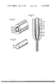
FIG. 1 is a view in oblique projection showing an example of an optical waveguide having a cylindrical layer with a high refractive index.
FIGS. 2 and 3 are views in oblique projection of a rod and a tube of fused silica respectively for explanation of an example of the method of manufacturing an optical waveguide according to the teachings of the present invention.
FIG. 4 is a view in longitudinal section of an optical waveguide presented for the purpose of explaining the manufacturing method of the present invention.
FIGS. 5 and 6 are views in obilque projection of a rod and tube of fused silica respectively for explanation of another example of the present invention.
FIG. 7 is a view in longitudinal section of an optical waveguide presented for the purpose of explaining another example of the present invention.
In FIG. 1, reference numeral 1 denotes the cylindrical layer of fused silica having a higher refractive index than that of the fused silica fiber composing the optical waveguide, reference numeral 2 the light transparent inner part of the optical fiber, and reference numeral 3 the light transparent outer part. Manufacturing methods of an optical waveguide as shown in FIG. 1 will be hereinafter explained.
FIG. 2 is a an oblique view of a transparent rod of pure fused silica sheathed by three thin layers, from inside to outside respectively of a fine powder of pure silica, a fine powder of purely doped silica of high refractive index and a fine powder of pure silica.
In FIG. 2, reference numeral 4 denotes the transparent rod, 5 and 7 cylindrical layers of the fine powder of pure silica, and 6 a cylindrical layer of a fine powder of purely doped silica of high refractive index.
In the manufacturing method of the present invention, the surface of the rod 4 is polished to be smooth and clean by optical polishing and flame polishing, etc. On the polished surface of the rod 4 a uniform thin layer 5 of fine powder of pure silica produces by oxidizing silicontetrachloride is applied to a thickness from several microns to several tens of microns. Then a fine powder layer is of pure silica containing one or more metal oxides, for example, TiO2 in an amount of several percent is deposited in a similar way to make layer 6 on the layer 5.
The thickness of the layer 6 is also made to be from several microns to several tens of microns.
A layer 7 of fine powder of pure silica is further deposited in a similar way to make a layer 5 whose thickness is nearly equal to the thickness of the layer 5.
After the abovementiond processes, a rod as shown in FIG. 2 is obtained.
FIG. 3 shows an oblique view of a transparent tube of the same material of the rod 4 which has a deposited layer on the inner surface thereof.
In FIG. 3, reference numeral 8 denotes a transparent tube whose dimensions of inner diameter and thickness must be determined in relation to the dimensions of a rod such as shown in FIG. 2 so that the optical fiber made by drawing the rod and tube in the subsequent process has the requisite dimensions of cross section reference numeral 9 denotes a layer of a fine powder of pure silica which is produced in a similar way as was done to make layer 5 of FIG. 2.
In the subsequent process, the rod as shown in FIG. 2 and the tube as shown in FIG. 3 are heated to approximately a temperature of nearly 1500° C to sinter the layers of fine powder of quartz 5, 6, 7, and 9 in an oxygen-rich atmosphere.
Then, as shown in FIG. 4, the rod of fused silica 4 is inserted coaxially in the tube of fused silica 8 and placed in a high temperature furnace. They are heated to a high temperature of approximately 1900° C to their melting point and are drawn into the form of a filament -- in other words, are spun -- to produce an optical waveguide of a requisite size and shape.
FIG. 4 shows a longitudinal section of the rod 4 and tube 8 which are spun under a high temperature.
In FIG. 4, the reference numerals 1, 2 and 3 show the same parts as shown in FIG. 1.
The optical waveguide thus manufactured has a shape as shown in FIG. 1 and has the undermentioned relationship between the refractive indexes n4, n5, n6, n7, n8 and n9 for parts 4, 5, 6, 7, 8 and 9 respectively, wherein n4 = n5 = n7 = n8 = n9 , n6 > n4.
As a result, the layer 6 of pure silica containing one or two metal oxides makes a cylindrical thin layer 1 of higher refractive index n6 by several % than the refractive index n4 or any of the others in the interior of the optical waveguide.
Then the layer 5 of pure silica and the rod 4 of fused silica are integrated into one body and made into the transparent rod 2 inside of the layer 1, while the layers 7 and 9 of pure silica and the tube 8 of fused silica are integrated into one body and tube into the transparent rube 3 outside of the layer 1. In the manufacturing method of the present invention, if the addition of TiO2 to the pure silica powder of layer 6 is precisely controlled to a requisite amount, an optical waveguide having a cylindrical layer 1 of an ideal refractive index n6 is successfully obtained.
The thickness of the layer 6 of the optical waveguide is made from one-severalths to one-several tenths of the transmitted wavelength.
In the process mentioned above, the layer 9 of the inner surface on the tube 8 is not necessary, if the thickness of the layer 7 on the rod 4 is made thicker. We can obtain the same type optical fiber from a rod having the layer 7 of fused silica as thick as the tube 8.
An optical waveguide of a cylindrical shaped film may also be obtained in a similar way as mentioned above by the following method explained by reference to FIGS. 5 - 7. In this method, a thin cylindrical layer 11 of a fine powder of pure silica, a thin cylindrical layer 12 of a fine powder of pure silica containing such an oxide as TiO2 and a thin cylindrical layer 13 of a fine powder of pure silica are deposited in turn one upon another of the inner surface of the tube 10 of fused silica. These deposited layers 11, 12 and 13 are prepared in the same way as layers 5, 6 and 7 are deposited on the surface of the rod 4. Likewise the layer 15 of a fine powder of pure silica is prepared on the outer surface of the rod 14 which is shown in FIG. 6.
As shown in FIG. 7, the tube 10 and rod 14 are heated in a furnace to sinter the layers. Then being so treated, tube 10 and rod 14 are inserted coaxially of each other and heated to a high temperature of about 1900° C and then are spun to a filament which composes an optical waveguide having cross sectional parts 1 2 and 3 as shown in FIG. 1. The light transmission properties of a fibrous optical waveguide obtained in the afore-mentioned way can be improved by giving it a suitable heat treatment. For example, fiber obtained in the afore-mentioned way is then heated to about 800° C for several hours and its surface is made clean by etching and polishing with HF acid in order to strengthen the fiber.
As a metallic oxide to be contained in the fine powder of purely doped silica of the layer 6 or 12, tantalum oxide, tin oxide, niobium oxide, zirconium oxide, aluminum oxide, ytterbium oxide, lanthanum oxide, cesium oxide, rubidium oxide, germanium oxide etc. which are oxides that belong to III, IV and V atom groups may also serve the purpose beside TiO2.
In the manufacturing method of the present invention, the thin layers of pure silica are interposed between the layer of purely doped silica having a high refractive index and the rod or tube of quartz, and are so melted and integrated to one body with the rod or tube during the spinning process so that the inner and outer surfaces of the layer of high refractive index are extremely smooth and clean due to the layers of pure silica, even if convexities and concavities on the surfaces of the rod and tube have not been sufficiently removed by polishing.
In consequence, the roughness of the surface of the rod and tube is covered up and eliminated by the interposed layers of pure silica, so that the effects of a smooth surface of the rod and tube can be obtained. It is, therefore, not necessary to carry out precise polishing of the surfaces of the rod and tube.
The present invention makes it possible to manufacture without difficulty an optical waveguide which has a very low light transmission loss due to the small scattering loss at the interfaces with a cylindrical thin layer of higher refractive index.
The manufacturing method of the present invention is broadly applicable to many types of optical waveguides. By practicing the method of the present invention one can easily obtain, for example, a clad type optical waveguide wherein a tube of fused silica having a layer of pure fused silica and a layer of purely doped fused silica containing one or two metallic oxides deposited on the inner surface of the tube one after another is melted and spun to a clad type optical fiber. One can also obtain a clad type optical waveguide wherein a tube of fused silica having a layer of fine powder of pure fused silica and a layer of fine powdered purely doped silica containing one or more metallic oxides deposited on its inner surface one after another and sintered in an oxygen-rich atmosphere is melted and spun to a fiber.
Claims (18)
1. A method of manufacturing an optical waveguide comprising the steps of,
providing an elongated member of fused silica having a smooth cylindrical surface,
forming a layer of fused silica on said smooth surface,
forming a thin layer of doped fused silica having an index of refraction greater than that of said fused silica over said layer of fused silica,
forming a second layer of fused silica over said layer of doped fused silica,
heating the composite structure so formed to the drawing temperature of the materials thereof, and
drawing the heated structure to reduce the cross-sectional area thereof and form an optical waveguide having a cylindrical layer of higher refractive index interposed between a core and an outer cylindrical layer of lesser refractive index.
2. The method of claim 1 wherein said elongated member of fused silica is a solid rod.
3. The method of claim 2, immediately prior to the step of heating, including the step of inserting said composite structure so formed coaxially within a tube of fused silica to form a new composite structure for heating.
4. The method of claim 3 including the step of forming a layer of fused silica on the inner surface of said tube prior to the step of inserting.
5. The method of claim 1 wherein said elongated member of fused silica is a tube and said smooth cylindrical surface is the inner surface of said tube.
6. The method of claim 5, immediately prior to the step of heating, including the step of inserting a rod of fused silica coaxially inside said composite tube structure so formed to form a new composite structure for heating.
7. The method of claim 6 including the step of forming a layer of fused silica on said rod prior to the step of inserting.
8. The method of claim 1, subsequent to the step of drawing, heat treating the drawn optical waveguide in an oxygen-rich atmosphere.
9. The method of claim 8 including the step of etching and polishing the heat treated optical waveguide by means of HF acid.
10. A method of manufacturing an optical waveguide comprising the steps of,
providing an elongated member of fused silica having a smooth cylindrical surface,
applying a layer of fine powder of fused silica on said smooth surface,
applying a thin layer of fine powder of doped silica having an index of refraction greater than that of said fused silica over said layer of fused silica,
applying a second layer of fine powder of fused silica over said layer of doped fused silica,
sintering said layers of fine powder in an oxygen-rich atmosphere,
heating the sintered conmposite structure so formed to the drawing temperature of the materials thereof, and
drawing the heated structure to reduce the cross-sectional area thereof and form an optical waveguide having a cylindrical layer of higher refractive index interposed betweenn a core and an outer cylindrical layer of lesser refractive index.
11. The method of claim 10 wherein said elongated member of fused silica is a solid rod.
12. The method of claim 11, immediately prior to the step of heating, including the step of inserting said composite structure so formed coaxially within a tube of fused silica to form a new composite structure for heating.
13. The method of claim 11, immediately prior to the step of sintering, including the step of applying a layer of fine powder of fused silica on the inner surface of a tube of fused silica prior to the step of sintering; and subsequent to the step of sintering but prior to the step of heating, inserting said sintered composite rod structure so formed coaxially within said tube of fused silica having an inner layer of sintered powder of fused silica to form a new composite structure for heating.
14. The method of claim 10 wherein said elongated member of fused silica is a tube and said smooth cylindrical surface is the inner surface of said tube.
15. The method of claim 14, immediately prior to the step of heating, including the step of inserting a rod of fused silica coaxially inside said sintered composite tube structure so formed to form a new composite structure for heating.
16. The method of claim 14 immediately prior to the step of sintering, including the step of applying a layer of powder of fused silica on a rod of fused silica, and subsequent to the step of sintering but prior to the step of heating, including the step of inserting the rod of fused silica having said sintered layer of powder of fused silica thereon coaxially inside said composite tube structure so formed to form a new composite structure for heating.
17. The method of claim 10, subsequent to the step of drawing, heat treating the drawn optical waveguide in an oxygen-rich atmosphere.
18. The method of claim 17, including the step of etching and polishing the heat treated optical waveguide by means of HF acid.
Priority Applications (1)
| Application Number | Priority Date | Filing Date | Title |
|---|---|---|---|
| US05/708,640 US4088388A (en) | 1972-10-13 | 1976-07-26 | O-Type optical waveguide |
Applications Claiming Priority (4)
| Application Number | Priority Date | Filing Date | Title |
|---|---|---|---|
| JP47-102840 | 1972-10-13 | ||
| JP47-102839 | 1972-10-13 | ||
| JP10284072A JPS5419492B2 (en) | 1972-10-13 | 1972-10-13 | |
| JP10283972A JPS5514070B2 (en) | 1972-10-13 | 1972-10-13 |
Related Child Applications (1)
| Application Number | Title | Priority Date | Filing Date |
|---|---|---|---|
| US05/708,640 Division US4088388A (en) | 1972-10-13 | 1976-07-26 | O-Type optical waveguide |
Publications (1)
| Publication Number | Publication Date |
|---|---|
| US4123483A true US4123483A (en) | 1978-10-31 |
Family
ID=26443523
Family Applications (1)
| Application Number | Title | Priority Date | Filing Date |
|---|---|---|---|
| US05/406,112 Expired - Lifetime US4123483A (en) | 1972-10-13 | 1973-10-12 | Manufacturing method of an optical waveguide |
Country Status (5)
| Country | Link |
|---|---|
| US (1) | US4123483A (en) |
| DE (1) | DE2351354C3 (en) |
| FR (1) | FR2224415B1 (en) |
| GB (1) | GB1434977A (en) |
| NL (1) | NL176660C (en) |
Cited By (24)
| Publication number | Priority date | Publication date | Assignee | Title |
|---|---|---|---|---|
| FR2450790A1 (en) * | 1979-03-07 | 1980-10-03 | Int Standard Electric Corp | METHOD FOR MANUFACTURING OPTICAL FIBER OR OPTICAL FIBER PREFORM AND PRODUCTS OBTAINED |
| US4251251A (en) * | 1979-05-31 | 1981-02-17 | Corning Glass Works | Method of making optical devices |
| US4264347A (en) * | 1978-12-29 | 1981-04-28 | Ltd. Dainichi-Nippon Cables | Method of fabricating optical fiber preforms |
| US4276072A (en) * | 1977-06-07 | 1981-06-30 | International Telephone And Telegraph Corporation | Optical fiber fabrication |
| US4283213A (en) * | 1979-10-22 | 1981-08-11 | International Telephone And Telegraph Corporation | Method of fabrication of single mode optical fibers or waveguides |
| US4407668A (en) * | 1977-09-30 | 1983-10-04 | Siemens Aktiengesellschaft | Apparatus and process for producing a cladded optical fiber having a longitudinal side coupling zone |
| US4455267A (en) * | 1980-07-31 | 1984-06-19 | Rockwell International Corporation | Fabrication of birefringent electromagnetic transmission line |
| US4465336A (en) * | 1980-12-16 | 1984-08-14 | Licentia Patent-Verwaltungs-Gmbh | Waveguide and method of manufacturing same |
| US4551162A (en) * | 1984-10-01 | 1985-11-05 | Polaroid Corporation | Hollow tube method for forming an optical fiber |
| EP0182250A1 (en) * | 1984-11-13 | 1986-05-28 | Sumitomo Electric Industries Limited | Method for producing glass preform for optical fiber |
| US4594763A (en) * | 1984-12-21 | 1986-06-17 | At&T Technologies, Inc. | Method and apparatus for inserting a glass rod into a glass tube |
| EP0253427A1 (en) * | 1986-07-14 | 1988-01-20 | Koninklijke Philips Electronics N.V. | Method for making optical fibres with a core and an envelope from glass using the rod-in-tube method |
| US4737179A (en) * | 1985-08-14 | 1988-04-12 | Sumitomo Electric Industries, Ltd. | Method for producing glass preform for optical fiber |
| US4749396A (en) * | 1985-01-25 | 1988-06-07 | Polaroid Corporation | Method of forming an optical fiber preform |
| US4820322A (en) * | 1986-04-28 | 1989-04-11 | American Telephone And Telegraph Company At&T Bell Laboratories | Method of and apparatus for overcladding a glass rod |
| US4886538A (en) * | 1987-07-28 | 1989-12-12 | Polaroid Corporation | Process for tapering waveguides |
| US4986939A (en) * | 1986-05-23 | 1991-01-22 | Schott Glaswerke | Method for the production of cylindrically symmetric bodies with a radial gradient |
| US5059230A (en) * | 1990-01-22 | 1991-10-22 | At&T Bell Laboratories | Fabrication of doped filament optical fibers |
| US5585150A (en) * | 1994-09-08 | 1996-12-17 | Mulch Developement Company | Mulch product and process for its preparation |
| WO2002098806A1 (en) * | 2001-05-31 | 2002-12-12 | Corning Incorporated | Method of manufacturing an optical fiber from a perform and optical fiber made by the method |
| US20020186950A1 (en) * | 2001-05-10 | 2002-12-12 | Tony Mule' | Optical waveguides formed from nano air-gap inter-layer dielectric materials and methods of fabrication thereof |
| US20060121226A1 (en) * | 2002-11-29 | 2006-06-08 | Fuji Photo Flim Co., Ltd. | Preform for producing plastic optical components, method of fabricating the preform, and plastic optical fiber |
| WO2015077262A1 (en) * | 2013-11-19 | 2015-05-28 | Guill Tool & Engineering | Coextruded, multilayered and multicomponent 3d printing inputs |
| US20160136887A1 (en) * | 2013-11-19 | 2016-05-19 | Guill Tool & Engineering Co., Inc. | Coextruded, multilayer and multicomponent 3d printing inputs |
Families Citing this family (3)
| Publication number | Priority date | Publication date | Assignee | Title |
|---|---|---|---|---|
| FR2487811B1 (en) * | 1980-07-31 | 1985-07-26 | France Etat | PROCESS AND PLANT FOR CONTINUOUSLY MANUFACTURING OPTICAL FIBERS |
| GB2231168A (en) * | 1989-04-27 | 1990-11-07 | Stc Plc | Optical fibres |
| GB2231169A (en) * | 1989-04-27 | 1990-11-07 | Stc Plc | Optical fibres |
Citations (4)
| Publication number | Priority date | Publication date | Assignee | Title |
|---|---|---|---|---|
| US3646473A (en) * | 1969-04-10 | 1972-02-29 | Young Charles G | Clad glass laser rod |
| US3711262A (en) * | 1970-05-11 | 1973-01-16 | Corning Glass Works | Method of producing optical waveguide fibers |
| US3737293A (en) * | 1972-01-03 | 1973-06-05 | Corning Glass Works | Method of forming an economic optical waveguide fiber |
| US3775075A (en) * | 1972-01-03 | 1973-11-27 | Corning Glass Works | Method of forming optical waveguide fibers |
Family Cites Families (3)
| Publication number | Priority date | Publication date | Assignee | Title |
|---|---|---|---|---|
| GB1145630A (en) * | 1966-10-18 | 1969-03-19 | Standard Telephones Cables Ltd | Dielectric waveguide |
| GB1406870A (en) * | 1970-05-11 | 1975-09-17 | Corning Glass Works | Method of forming an economic optical waveguide fibre |
| CA951555A (en) * | 1970-05-11 | 1974-07-23 | Robert D. Maurer | Glass optical waveguide |
-
1973
- 1973-10-11 GB GB4742773A patent/GB1434977A/en not_active Expired
- 1973-10-12 US US05/406,112 patent/US4123483A/en not_active Expired - Lifetime
- 1973-10-12 NL NLAANVRAGE7314032,A patent/NL176660C/en not_active IP Right Cessation
- 1973-10-12 DE DE2351354A patent/DE2351354C3/en not_active Expired
- 1973-10-12 FR FR7336536A patent/FR2224415B1/fr not_active Expired
Patent Citations (4)
| Publication number | Priority date | Publication date | Assignee | Title |
|---|---|---|---|---|
| US3646473A (en) * | 1969-04-10 | 1972-02-29 | Young Charles G | Clad glass laser rod |
| US3711262A (en) * | 1970-05-11 | 1973-01-16 | Corning Glass Works | Method of producing optical waveguide fibers |
| US3737293A (en) * | 1972-01-03 | 1973-06-05 | Corning Glass Works | Method of forming an economic optical waveguide fiber |
| US3775075A (en) * | 1972-01-03 | 1973-11-27 | Corning Glass Works | Method of forming optical waveguide fibers |
Cited By (30)
| Publication number | Priority date | Publication date | Assignee | Title |
|---|---|---|---|---|
| US4276072A (en) * | 1977-06-07 | 1981-06-30 | International Telephone And Telegraph Corporation | Optical fiber fabrication |
| US4407668A (en) * | 1977-09-30 | 1983-10-04 | Siemens Aktiengesellschaft | Apparatus and process for producing a cladded optical fiber having a longitudinal side coupling zone |
| US4264347A (en) * | 1978-12-29 | 1981-04-28 | Ltd. Dainichi-Nippon Cables | Method of fabricating optical fiber preforms |
| US4518407A (en) * | 1979-03-07 | 1985-05-21 | International Standard Electric Corporation | Optical fibre preform manufacture |
| FR2450790A1 (en) * | 1979-03-07 | 1980-10-03 | Int Standard Electric Corp | METHOD FOR MANUFACTURING OPTICAL FIBER OR OPTICAL FIBER PREFORM AND PRODUCTS OBTAINED |
| US4251251A (en) * | 1979-05-31 | 1981-02-17 | Corning Glass Works | Method of making optical devices |
| US4283213A (en) * | 1979-10-22 | 1981-08-11 | International Telephone And Telegraph Corporation | Method of fabrication of single mode optical fibers or waveguides |
| US4455267A (en) * | 1980-07-31 | 1984-06-19 | Rockwell International Corporation | Fabrication of birefringent electromagnetic transmission line |
| US4465336A (en) * | 1980-12-16 | 1984-08-14 | Licentia Patent-Verwaltungs-Gmbh | Waveguide and method of manufacturing same |
| US4551162A (en) * | 1984-10-01 | 1985-11-05 | Polaroid Corporation | Hollow tube method for forming an optical fiber |
| EP0182250A1 (en) * | 1984-11-13 | 1986-05-28 | Sumitomo Electric Industries Limited | Method for producing glass preform for optical fiber |
| US4668263A (en) * | 1984-11-13 | 1987-05-26 | Sumitomo Electric Industries, Ltd. | Method for producing glass preform for optical fiber |
| AU578983B2 (en) * | 1984-11-13 | 1988-11-10 | Sumitomo Electric Industries, Ltd. | Method for producing glass preform for optical fiber |
| US4594763A (en) * | 1984-12-21 | 1986-06-17 | At&T Technologies, Inc. | Method and apparatus for inserting a glass rod into a glass tube |
| US4749396A (en) * | 1985-01-25 | 1988-06-07 | Polaroid Corporation | Method of forming an optical fiber preform |
| US4737179A (en) * | 1985-08-14 | 1988-04-12 | Sumitomo Electric Industries, Ltd. | Method for producing glass preform for optical fiber |
| US4820322A (en) * | 1986-04-28 | 1989-04-11 | American Telephone And Telegraph Company At&T Bell Laboratories | Method of and apparatus for overcladding a glass rod |
| US4986939A (en) * | 1986-05-23 | 1991-01-22 | Schott Glaswerke | Method for the production of cylindrically symmetric bodies with a radial gradient |
| EP0253427A1 (en) * | 1986-07-14 | 1988-01-20 | Koninklijke Philips Electronics N.V. | Method for making optical fibres with a core and an envelope from glass using the rod-in-tube method |
| US4886538A (en) * | 1987-07-28 | 1989-12-12 | Polaroid Corporation | Process for tapering waveguides |
| US5059230A (en) * | 1990-01-22 | 1991-10-22 | At&T Bell Laboratories | Fabrication of doped filament optical fibers |
| US5585150A (en) * | 1994-09-08 | 1996-12-17 | Mulch Developement Company | Mulch product and process for its preparation |
| US6947651B2 (en) | 2001-05-10 | 2005-09-20 | Georgia Tech Research Corporation | Optical waveguides formed from nano air-gap inter-layer dielectric materials and methods of fabrication thereof |
| US20020186950A1 (en) * | 2001-05-10 | 2002-12-12 | Tony Mule' | Optical waveguides formed from nano air-gap inter-layer dielectric materials and methods of fabrication thereof |
| US20030089133A1 (en) * | 2001-05-31 | 2003-05-15 | Corning Incorporated | Method of forming a glass article by collapsing an annular passage of a preform during draw |
| WO2002098806A1 (en) * | 2001-05-31 | 2002-12-12 | Corning Incorporated | Method of manufacturing an optical fiber from a perform and optical fiber made by the method |
| US20060121226A1 (en) * | 2002-11-29 | 2006-06-08 | Fuji Photo Flim Co., Ltd. | Preform for producing plastic optical components, method of fabricating the preform, and plastic optical fiber |
| WO2015077262A1 (en) * | 2013-11-19 | 2015-05-28 | Guill Tool & Engineering | Coextruded, multilayered and multicomponent 3d printing inputs |
| US20160136887A1 (en) * | 2013-11-19 | 2016-05-19 | Guill Tool & Engineering Co., Inc. | Coextruded, multilayer and multicomponent 3d printing inputs |
| US10730232B2 (en) * | 2013-11-19 | 2020-08-04 | Guill Tool & Engineering Co, Inc. | Coextruded, multilayer and multicomponent 3D printing inputs |
Also Published As
| Publication number | Publication date |
|---|---|
| FR2224415B1 (en) | 1976-05-07 |
| NL176660B (en) | 1984-12-17 |
| DE2351354B2 (en) | 1976-07-01 |
| DE2351354A1 (en) | 1974-05-02 |
| GB1434977A (en) | 1976-05-12 |
| NL7314032A (en) | 1974-04-16 |
| DE2351354C3 (en) | 1981-06-11 |
| FR2224415A1 (en) | 1974-10-31 |
| NL176660C (en) | 1985-05-17 |
Similar Documents
| Publication | Publication Date | Title |
|---|---|---|
| US4123483A (en) | Manufacturing method of an optical waveguide | |
| US3823995A (en) | Method of forming light focusing fiber waveguide | |
| US3877912A (en) | Method of producing an optical transmission line | |
| US3932162A (en) | Method of making glass optical waveguide | |
| US4243298A (en) | High-strength optical preforms and fibers with thin, high-compression outer layers | |
| US4561871A (en) | Method of making polarization preserving optical fiber | |
| US4225330A (en) | Process for producing glass member | |
| FI68391C (en) | CONTAINER CONTAINER FOIL FRAMEWORK FOR FRAMSTAELLNING AV ETT AEMNE FOER EN OPTISK VAOGLEDARE | |
| US3933453A (en) | Flame hydrolysis mandrel and method of using | |
| JPH0425210B2 (en) | ||
| KR830006127A (en) | Manufacturing method of optical fiber and suit preform formed from optical waveguide suit preform and preform | |
| US4351658A (en) | Manufacture of optical fibers | |
| US4749396A (en) | Method of forming an optical fiber preform | |
| US4453962A (en) | Method of manufacturing a flexible optical fiber bundle | |
| US4088388A (en) | O-Type optical waveguide | |
| US4087266A (en) | Optical fibre manufacture | |
| EP0738239B1 (en) | Optical preform with controlled and deeply placed radial bonded interface layer | |
| CA1121160A (en) | Method of manufacturing optical fibers | |
| US4163654A (en) | Method of manufacturing graded index optical fibers | |
| US4708726A (en) | Fabrication of a lightguide preform by the outside vapor deposition process | |
| US4549891A (en) | Method for forming a non-symmetrical optical fiber | |
| JPS6313944B2 (en) | ||
| JP2988524B2 (en) | Optical fiber and method for manufacturing the same | |
| JP2616087B2 (en) | Manufacturing method of elliptical core type polarization maintaining optical fiber | |
| JP3923282B2 (en) | Manufacturing method of optical fiber for mode field conversion |