US4149772A - Optical fibre having low mode dispersion - Google Patents
Optical fibre having low mode dispersion Download PDFInfo
- Publication number
- US4149772A US4149772A US05/855,408 US85540877A US4149772A US 4149772 A US4149772 A US 4149772A US 85540877 A US85540877 A US 85540877A US 4149772 A US4149772 A US 4149772A
- Authority
- US
- United States
- Prior art keywords
- core
- rings
- light transmitting
- refractive index
- light
- Prior art date
- Legal status (The legal status is an assumption and is not a legal conclusion. Google has not performed a legal analysis and makes no representation as to the accuracy of the status listed.)
- Expired - Lifetime
Links
Images

Classifications
-
- G—PHYSICS
- G02—OPTICS
- G02B—OPTICAL ELEMENTS, SYSTEMS OR APPARATUS
- G02B6/00—Light guides; Structural details of arrangements comprising light guides and other optical elements, e.g. couplings
- G02B6/02—Optical fibres with cladding with or without a coating
- G02B6/036—Optical fibres with cladding with or without a coating core or cladding comprising multiple layers
- G02B6/03616—Optical fibres characterised both by the number of different refractive index layers around the central core segment, i.e. around the innermost high index core layer, and their relative refractive index difference
- G02B6/03688—Optical fibres characterised both by the number of different refractive index layers around the central core segment, i.e. around the innermost high index core layer, and their relative refractive index difference having 5 or more layers
-
- G—PHYSICS
- G02—OPTICS
- G02B—OPTICAL ELEMENTS, SYSTEMS OR APPARATUS
- G02B6/00—Light guides; Structural details of arrangements comprising light guides and other optical elements, e.g. couplings
- G02B6/02—Optical fibres with cladding with or without a coating
- G02B6/02042—Multicore optical fibres
-
- G—PHYSICS
- G02—OPTICS
- G02B—OPTICAL ELEMENTS, SYSTEMS OR APPARATUS
- G02B6/00—Light guides; Structural details of arrangements comprising light guides and other optical elements, e.g. couplings
- G02B6/02—Optical fibres with cladding with or without a coating
- G02B6/028—Optical fibres with cladding with or without a coating with core or cladding having graded refractive index
- G02B6/0288—Multimode fibre, e.g. graded index core for compensating modal dispersion
-
- G—PHYSICS
- G02—OPTICS
- G02B—OPTICAL ELEMENTS, SYSTEMS OR APPARATUS
- G02B6/00—Light guides; Structural details of arrangements comprising light guides and other optical elements, e.g. couplings
- G02B6/02—Optical fibres with cladding with or without a coating
- G02B6/02295—Microstructured optical fibre
- G02B6/023—Microstructured optical fibre having different index layers arranged around the core for guiding light by reflection, i.e. 1D crystal, e.g. omniguide
-
- G—PHYSICS
- G02—OPTICS
- G02B—OPTICAL ELEMENTS, SYSTEMS OR APPARATUS
- G02B6/00—Light guides; Structural details of arrangements comprising light guides and other optical elements, e.g. couplings
- G02B6/10—Light guides; Structural details of arrangements comprising light guides and other optical elements, e.g. couplings of the optical waveguide type
- G02B6/14—Mode converters
Definitions
- This invention relates to optical fibres having low mode dispersion, particularly as used for communications systems.
- An optical fibre conveys, or transmits, light from an input end to an output end by the phenomenon of internal reflection.
- a fibre generally comprises a core surrounded by a cladding and the light is retained within the core by the internal reflection.
- mode dispersion causes pulse spreading. Differential mode delay can be eliminated if a fibre is allowed to propagate only a single fundamental mode. However this requires the fibre to have a small core diameter, making fibre splicing and connecting difficult. Also, single-mode lasing sources are required for efficient light insertion into such a single-mode fibre. The diameter of the core cannot be arbitrarily increased by reducing the numerical aperture as too small a numerical aperture requires a thick cladding for containment of the evanescent wave and also too large a radius of curvature for low bending losses.
- the present invention provides an optical fibre having a cross-section area which enables efficient coupling and a fairly large numerical aperture and which substantially eliminates mode dispersion.
- An optical fibre, in accordance with the present invention in addition to a light transmitting core, also has one or more rings around the core--each transmitting light, with a ring of "cladding" material, that is material having a refractory index lower than the light transmitting material on each side thereof.
- An alternative arrangement has a core of "cladding” material with alternate rings also of "cladding” material, with the intermediate rings light transmitting.
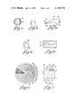
- FIG. 1 is a cross-section through one known form of optical fibre having a stepped refractory index
- FIG. 2 illustrates the form of the refractive index curve for the fibre of FIG. 1;
- FIG. 3 is a longitudinal cross-section of a fibre of the form of FIG. 1, illustrating light ray propagation therein;
- FIG. 4 is a curve illustrating the refractive index characteristic of another known form of optical fibre
- FIG. 5 is a longitudinal cross-section of the known form of fibre, the refractive index characteristic of which is illustrated in FIG. 4;
- FIG. 6 is a cross-section through a further form of optical fibre in accordance with the present invention.
- FIG. 7 is a curve illustrating the refractive index characteristic of the fibre of FIG. 6;
- FIG. 8 is a cross-section through yet a further form of optical fibre in accordance with the present invention.
- FIG. 9 is a curve illustrating the refractive index characteristic of the fibre of FIG. 8;
- FIGS. 10 and 11 are curves illustrating the refractive index characteristics of two further forms of optical fibre in accordance with the present invention.
- an optical fibre conveys, or transmits, light from an input end to an output end by the phenomenon of internal reflection.
- One form of optical fibre has a core 10 and a cladding 11, as illustrated in FIG. 1, with the core 10 having one refractive index and the cladding 11 a lower refractive index--as seen in FIG. 2.
- Waveguiding occurs via internal reflection for all light rays launched within the full cone angle ⁇ as illustrated in FIG. 3.
- the cone angle ⁇ is given by the numerical aperture (NA):
- n is the refractive index of the core 10 and n(1- ⁇ ) is the refractive index of the cladding 11.
- the core diameter D, NA, and cladding thickness T all determine the nature of modes propagating along the fibre.
- a light ray 12 launched at a large angle to the fibre axis near the critical angle ⁇ /2 will experience a large number of reflections at the core/cladding interface 13, compared to a light ray 14 entering at a shallower angle.
- the time delay difference between these highest and lowest order modes is:
- This differential mode delay is termed mode dispersion and causes pulse spreading even with monochromatic light.
- the frequency--length product bandwidth of the step-index fibre is thus limited at about 5 to 40 MHz-km.
- the fibre's information capacity is limited essentially by chromatic material dispersion (about 0.8 to 1 ns/km per 100 A of source spectral width in the GaAlAs range of 8000 to 8600A).
- D the core diameter
- This is a small core cross-section and makes splicing and connecting difficult.
- single-mode lasing sources are required for efficient light insertion into such a single-mode fibre.
- the diameter D cannot be arbitrarily increased by reducing the NA, since too small an NA requires too thick a cladding for containment of the evanescent wave and too large a radius of curvature for low bending losses.
- optical fibre has a core with a non-uniform refractive index. This is illustrated in FIGS. 4 and 5, FIG. 4 showing the core refractive index decreasing approximately parabolically, at 16.
- the cladding has a lower refractive index, as in the fibre of FIGS. 1 to 3.
- light rays 17 follow quasi-sinusoidal paths, rather than a zig-zag one. Light travels a shorter distance in regions of high refractive index than in regions of low index in a given time and this tends to equalize the average velocities of the various rays.
- the time delay between highest and lowest order modes 17 and 18 respectively is
- k is a number ranging from 1/8 to about 2 depending upon the accuracy with which the profile is maintained; ⁇ in %.
- graded index fibres With fibres of the non-uniform, or graded, refractive index, mode delays of 1/2 to 2 ns/km have been obtained. Manufacturing tolerances must be extremely tight if the theoretical limits of 1/64-1 ns/km are to be achieved.
- a disadvantage of graded index fibres is that they accept only half as much light from an incoherent source as do step-index fibres, and also require twice the curvature radius in bends.
- graded index fibres when produced from a concentric double crucibles require a fast ion diffusion exchange on the fibre drawing step.
- soft glasses of attenuation higher than that of fused silica are used, small cores of 30 to less than 50 ⁇ m diameter are produced, and it is difficult to attain a closely parabolic profile of the refractive index.
- Graded index fibres can also be produced by chemical vapour deposition (CVD) methods, but high precision in dopant concentrations is required.
- CVD chemical vapour deposition
- FIGS. 6 and 7 illustrate a fibre in accordance with one feature of the present invention.
- the fibre comprises a core 20 and a series of concentric rings or layers 21.
- the core 20 and each alternate ring, i.e. rings 22, 24, 26, 28 and 30 are of higher refractive index than the intervening and outer rings 21, 23, 25, 27, 29 and 31, as will be seen from FIG. 7.
- the light is conveyed through the core 20 and rings 22, 24, 26, 28 and 30.
- the thickness of each light conducting ring is reduced relative to the next inner ring and the innermost ring--22--is of a thickness slightly less than the radius of the core 20.
- a and b are the inner and outer radii of a light transmitting ring.
- the V and V r values of core 20 and rings 22, 24, 26, 28 and 30 should be approximately the same.
- the diameter of the core 20 and the inner and outer radii of the light transmitting rings are such that all areas are equal.
- the core/cladding index differences are held constant, that is index differences between core 20 and rings 22, 24, 26, 28 and 30 and the cladding rings 21, 23, 25, 27, 29 and 31, then the light transmitting ring thickness will decrease as radius increases. It is desirable that the thicknesses of the cladding rings 21, 23, 25, 27, 29 and 31 be large enough so that evanescent field coupling between the cores or light transmitting rings is minimized, as such coupling causes some spreading in modal velocities.
- the efficiency of input light insertion is related to the fraction of cross-sectional area occupied by core and light transmitting rays, and therefore the cladding ring thicknesses should not be too large.
- 30 to 50% of the total cross-section of a fibre is an optimum to be aimed at, for the light transmitting core and rings.
- the number of light conducting rings can vary, and to some extent is controlled by the NA.
- a large NA for example 0.2, reduces the number of rings, and a smaller NA--0.1--permits a larger number of rings.
- a small NA permits more and larger rings and a larger light source but light source must be more collimated than a small one.
- a larger NA requires less input light collimation and permits tighter bends.
- the arrangement of FIG. 6 gives a constant NA, with varying light transmitting ring thickness.
- FIGS. 8 and 9 relate to an optical fibre having a light transmitting core and a plurality of light transmitting rings in which there is a varying refractive index and constant ring thickness.
- the core can be of "cladding" that is of the lower refractive index and succeeding alternate rings also of cladding, with intermediate rings of high refractive index. That is, in FIG. 6, the refractive index as indicated in FIG. 7 can be reversed, although an outer ring of cladding will be required.
- ring thicknesses and index differences are both varied suitably.
- Multi ring optical fibres are readily produced by chemical vapour deposition (CVD), plasma deposition or flame hydrolysis, all known methods for producing optical fibres.
- CVD chemical vapour deposition
- plasma deposition plasma deposition
- flame hydrolysis all known methods for producing optical fibres.
- the doping level is constant and it is a matter of doping or not doping--so far as each dopant is concerned--for either a light transmitting ring or a "cladding" ring.
- a typical example of a process for CVD production of an optical fibre is as follows:
- a tube of fused silica is mounted for rotation about its longitudinal axis--the axis vertical.
- Oxygen is bubbled separately through reservoirs holding Si Cl 4 and Ge Cl 4 in liquid form, the oxygen picking up a vapour from the liquid.
- the oxygen and vapour from each reservoir are fed to a collecting chamber plus a direct flow of oxygen.
- the flows are combined and fed through the fused silica tube.
- the tube is rotated and a flame is traversed up and down the tube.
- the gases and vapour dissociate and oxidation of the silicon and germanium occur with a resultant deposition on the wall of the tube.
- the deposition is in the form of a sooty deposit which is fused onto the wall of the tube in the form of a glassy layer.
- Several passes of the flame are made to form a particular ring.
- the doping level is adjusted by varying the rate of oxygen flow through the germanium chloride solution.
- the tube is collapsed, again by passing the flame along the tube, but with a higher temperature so that the tube softens and collapses under surface tension forces.
- the collapsed tube is then pulled into a fibre in a conventional manner, for example by feeding into a furnace and pulling from the lower end and winding on a drum.
Abstract
An optical fibre has a core and a plurality of rings surrounding the core. In one arrangement the core and subsequent alternate rings are light transmitting, while the intermediate rings are of cladding material. In an alternative arrangement the core and alternate rings are of cladding material and intermediate rings are light transmitting. The light transmitting rings can be of varying refractive index or of constant refractive index.
Description
This application is a Continuation of application Ser. No. 615,223, filed Sept. 22, 1975.
This invention relates to optical fibres having low mode dispersion, particularly as used for communications systems.
An optical fibre conveys, or transmits, light from an input end to an output end by the phenomenon of internal reflection. A fibre generally comprises a core surrounded by a cladding and the light is retained within the core by the internal reflection.
One of the faults of conventional optical fibres is "mode dispersion," which causes pulse spreading. Differential mode delay can be eliminated if a fibre is allowed to propagate only a single fundamental mode. However this requires the fibre to have a small core diameter, making fibre splicing and connecting difficult. Also, single-mode lasing sources are required for efficient light insertion into such a single-mode fibre. The diameter of the core cannot be arbitrarily increased by reducing the numerical aperture as too small a numerical aperture requires a thick cladding for containment of the evanescent wave and also too large a radius of curvature for low bending losses.
The present invention provides an optical fibre having a cross-section area which enables efficient coupling and a fairly large numerical aperture and which substantially eliminates mode dispersion. An optical fibre, in accordance with the present invention, in addition to a light transmitting core, also has one or more rings around the core--each transmitting light, with a ring of "cladding" material, that is material having a refractory index lower than the light transmitting material on each side thereof. An alternative arrangement has a core of "cladding" material with alternate rings also of "cladding" material, with the intermediate rings light transmitting.
The invention will be readily understood by the following description of certain embodiments, by way of example, in conjunction with the accompanying diagrammatic drawings, in which:
FIG. 1 is a cross-section through one known form of optical fibre having a stepped refractory index;
FIG. 2 illustrates the form of the refractive index curve for the fibre of FIG. 1;
FIG. 3 is a longitudinal cross-section of a fibre of the form of FIG. 1, illustrating light ray propagation therein;
FIG. 4 is a curve illustrating the refractive index characteristic of another known form of optical fibre;
FIG. 5 is a longitudinal cross-section of the known form of fibre, the refractive index characteristic of which is illustrated in FIG. 4;
FIG. 6 is a cross-section through a further form of optical fibre in accordance with the present invention;
FIG. 7 is a curve illustrating the refractive index characteristic of the fibre of FIG. 6;
FIG. 8 is a cross-section through yet a further form of optical fibre in accordance with the present invention;
FIG. 9 is a curve illustrating the refractive index characteristic of the fibre of FIG. 8;
FIGS. 10 and 11 are curves illustrating the refractive index characteristics of two further forms of optical fibre in accordance with the present invention.
As previously stated, an optical fibre conveys, or transmits, light from an input end to an output end by the phenomenon of internal reflection. One form of optical fibre has a core 10 and a cladding 11, as illustrated in FIG. 1, with the core 10 having one refractive index and the cladding 11 a lower refractive index--as seen in FIG. 2. Waveguiding occurs via internal reflection for all light rays launched within the full cone angle φ as illustrated in FIG. 3. The cone angle φ is given by the numerical aperture (NA):
na≡sin φ/2=√n.sup.2 -n.sup.2 (1-Δ).sup.2 ≈n≧2Δ,
where n is the refractive index of the core 10 and n(1-Δ) is the refractive index of the cladding 11.
Typically, for low loss guides, Δ≈1/2% to 4%, NA≈0.15 to 0.42 and φ≈17° to 50°. The core diameter D, NA, and cladding thickness T, all determine the nature of modes propagating along the fibre. Thus, for example, a light ray 12 launched at a large angle to the fibre axis (near the critical angle φ/2) will experience a large number of reflections at the core/cladding interface 13, compared to a light ray 14 entering at a shallower angle. At the end of a length L of fibre the time delay difference between these highest and lowest order modes is:
τ.sub.s =(L/c)nΔ≈50Δns/km,
where c is the vacuum light velocity, Δ being in %.
This differential mode delay is termed mode dispersion and causes pulse spreading even with monochromatic light. The frequency--length product bandwidth of the step-index fibre is thus limited at about 5 to 40 MHz-km.
Differential mode dispersion is eliminated if the fibre is allowed to propagate only the single fundamental (HE11) mode. At a wavelength λ this occurs if the "V-value" of the guide satifies
V≡π(D/λ)·NA<2.405.
in single mode operation, the fibre's information capacity is limited essentially by chromatic material dispersion (about 0.8 to 1 ns/km per 100 A of source spectral width in the GaAlAs range of 8000 to 8600A). However this requires D, the core diameter, to be approximately equal to 1-5 μm. This is a small core cross-section and makes splicing and connecting difficult. As previously stated, single-mode lasing sources are required for efficient light insertion into such a single-mode fibre. The diameter D cannot be arbitrarily increased by reducing the NA, since too small an NA requires too thick a cladding for containment of the evanescent wave and too large a radius of curvature for low bending losses.
An alternative form of optical fibre has a core with a non-uniform refractive index. This is illustrated in FIGS. 4 and 5, FIG. 4 showing the core refractive index decreasing approximately parabolically, at 16. The cladding has a lower refractive index, as in the fibre of FIGS. 1 to 3. As seen in FIG. 5 light rays 17 follow quasi-sinusoidal paths, rather than a zig-zag one. Light travels a shorter distance in regions of high refractive index than in regions of low index in a given time and this tends to equalize the average velocities of the various rays. The time delay between highest and lowest order modes 17 and 18 respectively is
τ.sub.g =K(L/c)nΔ.sup.2 ≈(K/2)Δ.sup.2 ns/km
where k is a number ranging from 1/8 to about 2 depending upon the accuracy with which the profile is maintained; Δ in %.
With fibres of the non-uniform, or graded, refractive index, mode delays of 1/2 to 2 ns/km have been obtained. Manufacturing tolerances must be extremely tight if the theoretical limits of 1/64-1 ns/km are to be achieved. A disadvantage of graded index fibres is that they accept only half as much light from an incoherent source as do step-index fibres, and also require twice the curvature radius in bends.
In addition to the above disadvantages, graded index fibres when produced from a concentric double crucibles require a fast ion diffusion exchange on the fibre drawing step. Further, soft glasses of attenuation higher than that of fused silica are used, small cores of 30 to less than 50 μm diameter are produced, and it is difficult to attain a closely parabolic profile of the refractive index.
Graded index fibres can also be produced by chemical vapour deposition (CVD) methods, but high precision in dopant concentrations is required.
The present invention uses fibres having a "stepped" gradient for the refractive index while obtaining advantages of reduced mode dispersion. FIGS. 6 and 7 illustrate a fibre in accordance with one feature of the present invention. The fibre comprises a core 20 and a series of concentric rings or layers 21. The core 20 and each alternate ring, i.e. rings 22, 24, 26, 28 and 30 are of higher refractive index than the intervening and outer rings 21, 23, 25, 27, 29 and 31, as will be seen from FIG. 7. In the example of FIG. 6 the light is conveyed through the core 20 and rings 22, 24, 26, 28 and 30. The thickness of each light conducting ring is reduced relative to the next inner ring and the innermost ring--22--is of a thickness slightly less than the radius of the core 20.
All the rings 22, 24, 26, 28 and 30 have Vr values defined by the equation
V.sub.r ≡2(π/λ)√b.sup.2 -a.sup.2 ·NA
where a and b are the inner and outer radii of a light transmitting ring. To ensure that all modal group velocities are approximately equal, the V and Vr values of core 20 and rings 22, 24, 26, 28 and 30 should be approximately the same. Hence the diameter of the core 20 and the inner and outer radii of the light transmitting rings are such that all areas are equal. If the core/cladding index differences are held constant, that is index differences between core 20 and rings 22, 24, 26, 28 and 30 and the cladding rings 21, 23, 25, 27, 29 and 31, then the light transmitting ring thickness will decrease as radius increases. It is desirable that the thicknesses of the cladding rings 21, 23, 25, 27, 29 and 31 be large enough so that evanescent field coupling between the cores or light transmitting rings is minimized, as such coupling causes some spreading in modal velocities.
However, the efficiency of input light insertion is related to the fraction of cross-sectional area occupied by core and light transmitting rays, and therefore the cladding ring thicknesses should not be too large. As an indication, 30 to 50% of the total cross-section of a fibre is an optimum to be aimed at, for the light transmitting core and rings.
The number of light conducting rings can vary, and to some extent is controlled by the NA. A large NA, for example 0.2, reduces the number of rings, and a smaller NA--0.1--permits a larger number of rings. A small NA permits more and larger rings and a larger light source but light source must be more collimated than a small one. A larger NA requires less input light collimation and permits tighter bends. The arrangement of FIG. 6 gives a constant NA, with varying light transmitting ring thickness.
FIGS. 8 and 9 relate to an optical fibre having a light transmitting core and a plurality of light transmitting rings in which there is a varying refractive index and constant ring thickness. There is a light transmitting core 35 and light transmitting rings 37 and 39, and cladding rings 36, 38 and 40.
In both arrangements as in FIGS. 6 and 8, the core can be of "cladding" that is of the lower refractive index and succeeding alternate rings also of cladding, with intermediate rings of high refractive index. That is, in FIG. 6, the refractive index as indicated in FIG. 7 can be reversed, although an outer ring of cladding will be required.
In a further alternative, not shown, ring thicknesses and index differences are both varied suitably.
It is also possible to vary the refractive index for each ring across the ring thickness. Typical examples are shown in FIGS. 10 and 11, for an optical fibre arrangement as in FIG. 8, for example.
Multi ring optical fibres are readily produced by chemical vapour deposition (CVD), plasma deposition or flame hydrolysis, all known methods for producing optical fibres. There is a particular advantage in producing rings which have a constant refractive index across their thickness in that the doping can readily be obtained. The doping level is constant and it is a matter of doping or not doping--so far as each dopant is concerned--for either a light transmitting ring or a "cladding" ring.
For a graded refractive index it is more difficult as the doping level must be varied during the production of a ring. A typical example of a process for CVD production of an optical fibre is as follows:
A tube of fused silica is mounted for rotation about its longitudinal axis--the axis vertical. Oxygen is bubbled separately through reservoirs holding Si Cl4 and Ge Cl4 in liquid form, the oxygen picking up a vapour from the liquid. The oxygen and vapour from each reservoir are fed to a collecting chamber plus a direct flow of oxygen. The flows are combined and fed through the fused silica tube. The tube is rotated and a flame is traversed up and down the tube. At the heated position in the tube the gases and vapour dissociate and oxidation of the silicon and germanium occur with a resultant deposition on the wall of the tube. The deposition is in the form of a sooty deposit which is fused onto the wall of the tube in the form of a glassy layer. Several passes of the flame are made to form a particular ring. The doping level is adjusted by varying the rate of oxygen flow through the germanium chloride solution.
After the required number of rings have been formed, the tube is collapsed, again by passing the flame along the tube, but with a higher temperature so that the tube softens and collapses under surface tension forces. Thus the inner ring becomes the core. The collapsed tube is then pulled into a fibre in a conventional manner, for example by feeding into a furnace and pulling from the lower end and winding on a drum.
Claims (7)
1. An optical fibre having a plurality of concentric, spaced, light transmission paths, each path for transmission of the same single optical mode, comprising a core and at least three rings surrounding the core, said rings and core of alternate high refractive index light transmitting material and low refractive index cladding material, relative to one another, to provide at least two concentric light transmitting paths separated by cladding material, the cross-sectional area of each light transmitting path defined by:
V≈2(π/λ)√b.sup.2 -a.sup.2 ·NA
where NA=numerical aperture; a is the inner radius and b is the outer radius of the light transmitting path, λ is the wavelength and V is less than about 2.4.
2. An optical fibre as claimed in claim 1, said core and subsequent alternate rings being of cladding material and the intermediate rings of light transmission material to provide said at least two light transmitting paths.
3. A fibre as claimed in claim 1, the cross-sectional areas of the light transmitting paths equal and the difference in refractive index between each light path and the related cladding is constant.
4. A fibre as claimed in claim 3, the refractive index of each light path different and the cross-sectional area of the light paths different.
5. An optical fibre as claimed in claim 1, said core and subsequent alternate rings comprising said light transmission paths, the intermediate rings of cladding material.
6. An optical fibre as claimed in claim 5, the core and each light transmitting ring having a reducing radial thickness and a substantially constant relatively higher refractive index.
7. An optical fibre as claimed in claim 5, the core and each light transmitting ring of the same radial thickness, the refractive index of the core and light transmitting rings reducing stepwise.
Applications Claiming Priority (1)
| Application Number | Priority Date | Filing Date | Title |
|---|---|---|---|
| US61522375A | 1975-09-22 | 1975-09-22 |
Related Parent Applications (1)
| Application Number | Title | Priority Date | Filing Date |
|---|---|---|---|
| US61522375A Continuation | 1975-09-22 | 1975-09-22 |
Publications (1)
| Publication Number | Publication Date |
|---|---|
| US4149772A true US4149772A (en) | 1979-04-17 |
Family
ID=24464518
Family Applications (1)
| Application Number | Title | Priority Date | Filing Date |
|---|---|---|---|
| US05/855,408 Expired - Lifetime US4149772A (en) | 1975-09-22 | 1977-11-28 | Optical fibre having low mode dispersion |
Country Status (1)
| Country | Link |
|---|---|
| US (1) | US4149772A (en) |
Cited By (29)
| Publication number | Priority date | Publication date | Assignee | Title |
|---|---|---|---|---|
| US4252403A (en) * | 1979-11-06 | 1981-02-24 | International Telephone And Telegraph Corporation | Coupler for a graded index fiber |
| US4265515A (en) * | 1978-05-08 | 1981-05-05 | International Telephone And Telegraph Corporation | Optical fiber waveguide with effective refractive index profile |
| US4266851A (en) * | 1979-11-06 | 1981-05-12 | International Telephone And Telegraph Corporation | Coupler for a concentric core optical fiber |
| US4363533A (en) * | 1979-12-26 | 1982-12-14 | Gould Inc. | Concentric fiber optical transducer |
| EP0083843A2 (en) * | 1981-12-07 | 1983-07-20 | Corning Glass Works | Low dispersion, low-loss single-mode optical waveguide |
| EP0127408A1 (en) * | 1983-05-20 | 1984-12-05 | Corning Glass Works | Optical waveguide fiber |
| US4621896A (en) * | 1984-07-30 | 1986-11-11 | The United States Of America As Represented By The Secretary Of The Navy | Optical fibers with reduced pressure sensitivity to high frequency acoustic field |
| US4643752A (en) * | 1984-11-15 | 1987-02-17 | At&T Bell Laboratories | Fresnel lens fabrication |
| US4645523A (en) * | 1984-11-15 | 1987-02-24 | At&T Bell Laboratories | Fresnel lens fabrication |
| US4715695A (en) * | 1983-06-15 | 1987-12-29 | Sumitomo Electric Industries, Ltd. | Fiber for optical transmission |
| US4895420A (en) * | 1988-08-22 | 1990-01-23 | Gte Products Corporation | High reflectance light guide |
| US4923279A (en) * | 1987-10-22 | 1990-05-08 | British Telecommunications Plc | Optical fibre with fluorescent additive |
| US4936650A (en) * | 1986-04-24 | 1990-06-26 | British Telecommunications Public Limited Company | Optical wave guides |
| US4974933A (en) * | 1986-06-04 | 1990-12-04 | British Telecommunications Plc | Optical waveguides and their manufacture |
| US5013131A (en) * | 1988-04-12 | 1991-05-07 | Schott Glaswerke | Single-mode optical, fiber and process for its production |
| US5067793A (en) * | 1989-08-16 | 1991-11-26 | U.S. Philips Corporation | Polarization-maintaining single-mode optical fibre and method of making same |
| US5822488A (en) * | 1995-10-04 | 1998-10-13 | Sumitomo Electric Industries, Inc. | Single-mode optical fiber with plural core portions |
| WO1999008142A1 (en) * | 1997-08-07 | 1999-02-18 | Corning Incorporated | Dispersion managed optical waveguide fiber |
| EP1352273A1 (en) * | 2001-01-19 | 2003-10-15 | The University Of Sydney | An optical fibre |
| US6859598B2 (en) * | 2000-01-21 | 2005-02-22 | Sumitomo Electric Industries, Ltd. | Microstructured optical fiber |
| AU2002226190B2 (en) * | 2001-01-19 | 2007-12-13 | The University Of Melbourne | An optical fibre |
| US20080166094A1 (en) * | 2007-01-08 | 2008-07-10 | Corning Incorporated | Bend resistant multimode optical fiber |
| WO2008111945A2 (en) * | 2006-05-31 | 2008-09-18 | The Regents Of The University Of California | Optical fiber having wave-guiding rings |
| US20090154888A1 (en) * | 2007-12-13 | 2009-06-18 | Abbott Iii John Steele | Bend Resistant Multimode Optical Fiber |
| US20150309249A1 (en) * | 2014-04-29 | 2015-10-29 | Florida Institute of Technology, Inc. | All-optical spatial domain multiplexing de-multiplexer |
| US9481599B2 (en) | 2010-12-21 | 2016-11-01 | Corning Incorporated | Method of making a multimode optical fiber |
| US20180372958A1 (en) * | 2016-07-15 | 2018-12-27 | Light Field Lab, Inc. | System and methods for realizing transverse anderson localization in energy relays using component engineered structures |
| US10884251B2 (en) | 2018-01-14 | 2021-01-05 | Light Field Lab, Inc. | Systems and methods for directing multiple 4D energy fields |
| WO2021170748A1 (en) * | 2020-02-25 | 2021-09-02 | Biolitec Unternehmensbeteiligungs Ii Ag | Preforms for speckle-free output optical fibers having structured silica sections, methods of such preform manufacture, and improved speckle-free output optical fibers |
Citations (2)
| Publication number | Priority date | Publication date | Assignee | Title |
|---|---|---|---|---|
| US3157726A (en) * | 1960-03-01 | 1964-11-17 | American Optical Corp | Optical energy transmitting devices and method of making same |
| US4000416A (en) * | 1975-07-11 | 1976-12-28 | International Telephone And Telegraph Corporation | Multi-core optical communications fiber |
-
1977
- 1977-11-28 US US05/855,408 patent/US4149772A/en not_active Expired - Lifetime
Patent Citations (2)
| Publication number | Priority date | Publication date | Assignee | Title |
|---|---|---|---|---|
| US3157726A (en) * | 1960-03-01 | 1964-11-17 | American Optical Corp | Optical energy transmitting devices and method of making same |
| US4000416A (en) * | 1975-07-11 | 1976-12-28 | International Telephone And Telegraph Corporation | Multi-core optical communications fiber |
Cited By (57)
| Publication number | Priority date | Publication date | Assignee | Title |
|---|---|---|---|---|
| US4265515A (en) * | 1978-05-08 | 1981-05-05 | International Telephone And Telegraph Corporation | Optical fiber waveguide with effective refractive index profile |
| US4252403A (en) * | 1979-11-06 | 1981-02-24 | International Telephone And Telegraph Corporation | Coupler for a graded index fiber |
| US4266851A (en) * | 1979-11-06 | 1981-05-12 | International Telephone And Telegraph Corporation | Coupler for a concentric core optical fiber |
| US4363533A (en) * | 1979-12-26 | 1982-12-14 | Gould Inc. | Concentric fiber optical transducer |
| EP0083843A2 (en) * | 1981-12-07 | 1983-07-20 | Corning Glass Works | Low dispersion, low-loss single-mode optical waveguide |
| EP0083843B1 (en) * | 1981-12-07 | 1989-09-27 | Corning Glass Works | Low dispersion, low-loss single-mode optical waveguide |
| EP0127408A1 (en) * | 1983-05-20 | 1984-12-05 | Corning Glass Works | Optical waveguide fiber |
| US4715695A (en) * | 1983-06-15 | 1987-12-29 | Sumitomo Electric Industries, Ltd. | Fiber for optical transmission |
| US4621896A (en) * | 1984-07-30 | 1986-11-11 | The United States Of America As Represented By The Secretary Of The Navy | Optical fibers with reduced pressure sensitivity to high frequency acoustic field |
| US4643752A (en) * | 1984-11-15 | 1987-02-17 | At&T Bell Laboratories | Fresnel lens fabrication |
| US4645523A (en) * | 1984-11-15 | 1987-02-24 | At&T Bell Laboratories | Fresnel lens fabrication |
| US4936650A (en) * | 1986-04-24 | 1990-06-26 | British Telecommunications Public Limited Company | Optical wave guides |
| US4974933A (en) * | 1986-06-04 | 1990-12-04 | British Telecommunications Plc | Optical waveguides and their manufacture |
| USRE35946E (en) * | 1987-10-22 | 1998-11-03 | British Telecommunications Plc | Optical fibre amplifier with fluorescent additive and method of amplifying signals using same |
| US4923279A (en) * | 1987-10-22 | 1990-05-08 | British Telecommunications Plc | Optical fibre with fluorescent additive |
| US5013131A (en) * | 1988-04-12 | 1991-05-07 | Schott Glaswerke | Single-mode optical, fiber and process for its production |
| US4895420A (en) * | 1988-08-22 | 1990-01-23 | Gte Products Corporation | High reflectance light guide |
| US5067793A (en) * | 1989-08-16 | 1991-11-26 | U.S. Philips Corporation | Polarization-maintaining single-mode optical fibre and method of making same |
| US6295843B1 (en) | 1995-10-04 | 2001-10-02 | Sumitomo Electric Industries, Ltd. | Method of making a single-mode optical fiber with multiple concentric core portions by using an outside vapor deposition process |
| US6062046A (en) * | 1995-10-04 | 2000-05-16 | Sumitomo Electric Industries, Inc. | Method of making a single-mode optical fiber with multiple concentric core portions including the RIT process |
| US5822488A (en) * | 1995-10-04 | 1998-10-13 | Sumitomo Electric Industries, Inc. | Single-mode optical fiber with plural core portions |
| US6446469B2 (en) | 1995-10-04 | 2002-09-10 | Sumitomo Electric Industries, Ltd. | MCVD method with GE depletion to form a single mode optical fiber |
| US20030007761A1 (en) * | 1995-10-04 | 2003-01-09 | Sumitomo Electric Industries, Ltd. | Single-mode optical fiber and method of fabricating the same |
| WO1999008142A1 (en) * | 1997-08-07 | 1999-02-18 | Corning Incorporated | Dispersion managed optical waveguide fiber |
| AU731474B2 (en) * | 1997-08-07 | 2001-03-29 | Corning Incorporated | Dispersion managed optical waveguide fiber |
| US6317552B1 (en) * | 1997-08-07 | 2001-11-13 | Corning Incorporated | Dispersion managed optical waveguide fiber |
| US6859598B2 (en) * | 2000-01-21 | 2005-02-22 | Sumitomo Electric Industries, Ltd. | Microstructured optical fiber |
| EP1352273A4 (en) * | 2001-01-19 | 2006-08-09 | Univ Sydney | An optical fibre |
| AU2002226190B2 (en) * | 2001-01-19 | 2007-12-13 | The University Of Melbourne | An optical fibre |
| EP1352273A1 (en) * | 2001-01-19 | 2003-10-15 | The University Of Sydney | An optical fibre |
| US7907810B2 (en) | 2006-05-31 | 2011-03-15 | Lawrence Livermore National Security, Llc | Optical fiber having wave-guiding rings |
| WO2008111945A2 (en) * | 2006-05-31 | 2008-09-18 | The Regents Of The University Of California | Optical fiber having wave-guiding rings |
| US20080260338A1 (en) * | 2006-05-31 | 2008-10-23 | The Regents Of The University Of Ca | Optical fiber having wave-guiding rings |
| WO2008111945A3 (en) * | 2006-05-31 | 2008-11-27 | Univ California | Optical fiber having wave-guiding rings |
| US20080166094A1 (en) * | 2007-01-08 | 2008-07-10 | Corning Incorporated | Bend resistant multimode optical fiber |
| US7787731B2 (en) | 2007-01-08 | 2010-08-31 | Corning Incorporated | Bend resistant multimode optical fiber |
| US20090154888A1 (en) * | 2007-12-13 | 2009-06-18 | Abbott Iii John Steele | Bend Resistant Multimode Optical Fiber |
| US8406592B2 (en) | 2007-12-13 | 2013-03-26 | Corning Incorporated | Bend resistant multimode optical fiber |
| US9481599B2 (en) | 2010-12-21 | 2016-11-01 | Corning Incorporated | Method of making a multimode optical fiber |
| US20150309249A1 (en) * | 2014-04-29 | 2015-10-29 | Florida Institute of Technology, Inc. | All-optical spatial domain multiplexing de-multiplexer |
| US9529147B2 (en) * | 2014-04-29 | 2016-12-27 | Florida Institute of Technology, Inc. | All-optical spatial domain multiplexing de-multiplexer |
| KR20190027387A (en) * | 2016-07-15 | 2019-03-14 | 라이트 필드 랩, 인코포레이티드 | System and method for realizing transverse Anderson aliasing in energy relay using component engineered structures |
| US20180372958A1 (en) * | 2016-07-15 | 2018-12-27 | Light Field Lab, Inc. | System and methods for realizing transverse anderson localization in energy relays using component engineered structures |
| US11796733B2 (en) | 2016-07-15 | 2023-10-24 | Light Field Lab, Inc. | Energy relay and Transverse Anderson Localization for propagation of two-dimensional, light field and holographic energy |
| US11740402B2 (en) | 2016-07-15 | 2023-08-29 | Light Field Lab, Inc. | Energy relays with traverse energy localization |
| US11733448B2 (en) | 2016-07-15 | 2023-08-22 | Light Field Lab, Inc. | System and methods for realizing transverse Anderson localization in energy relays using component engineered structures |
| US11221670B2 (en) * | 2016-07-15 | 2022-01-11 | Light Field Lab, Inc. | System and methods for realizing transverse Anderson localization in energy relays using component engineered structures |
| US11681091B2 (en) | 2016-07-15 | 2023-06-20 | Light Field Lab, Inc. | High density energy directing device |
| US11280940B2 (en) | 2018-01-14 | 2022-03-22 | Light Field Lab, Inc. | Systems and methods for directing multiple 4D energy fields |
| US11237307B2 (en) | 2018-01-14 | 2022-02-01 | Light Field Lab, Inc. | Systems and methods for forming energy relays with transverse energy localization |
| US11719864B2 (en) | 2018-01-14 | 2023-08-08 | Light Field Lab, Inc. | Ordered geometries for optomized holographic projection |
| US11181749B2 (en) | 2018-01-14 | 2021-11-23 | Light Field Lab, Inc. | Systems and methods for transverse energy localization in energy relays using ordered structures |
| US10884251B2 (en) | 2018-01-14 | 2021-01-05 | Light Field Lab, Inc. | Systems and methods for directing multiple 4D energy fields |
| US20230408737A1 (en) * | 2018-01-14 | 2023-12-21 | Light Field Lab, Inc. | Ordered geometries for optomized holographic projection |
| US11885988B2 (en) | 2018-01-14 | 2024-01-30 | Light Field Lab, Inc. | Systems and methods for forming energy relays with transverse energy localization |
| CN115190870A (en) * | 2020-02-25 | 2022-10-14 | 拜欧利泰克投资二代公司 | Preform for speckle-free output fiber with structured silica sections, method of manufacturing such preform, and improved speckle-free output fiber |
| WO2021170748A1 (en) * | 2020-02-25 | 2021-09-02 | Biolitec Unternehmensbeteiligungs Ii Ag | Preforms for speckle-free output optical fibers having structured silica sections, methods of such preform manufacture, and improved speckle-free output optical fibers |
Similar Documents
| Publication | Publication Date | Title |
|---|---|---|
| US4149772A (en) | Optical fibre having low mode dispersion | |
| US4447127A (en) | Low loss single mode fiber | |
| EP2299303B1 (en) | Multimode optical fibre with reduced bending losses | |
| US4204745A (en) | Optical fiber | |
| US4222631A (en) | Multicomponent optical waveguide having index gradient | |
| US4715679A (en) | Low dispersion, low-loss single-mode optical waveguide | |
| US20090019894A1 (en) | Method for Manufacturing a Multimode Optical Fibre | |
| DK152631B (en) | PREFORM FOR WHICH A OPTICAL FILAMENT WITH HIGH BANDWISE AND INDEX GRADIENT CAN BE MADE, AND PROCEDURE FOR THE CREATION OF SUCH A PREFORM. | |
| GB1570767A (en) | Single mode optical transmission line | |
| US4053205A (en) | Optical fiber having reduced dispersion | |
| US8606065B2 (en) | Optical fiber and method for fabricating the same | |
| US4185890A (en) | Optical transmission line | |
| CN105829928A (en) | Design and manufacture of multi-mode optical fibers | |
| US4053204A (en) | Optical fiber having reduced dispersion | |
| US6990277B2 (en) | Enhanced multimode fiber | |
| EP0127408B2 (en) | Optical waveguide fiber | |
| US5867616A (en) | Polarization mode coupled single mode waveguide | |
| US4205901A (en) | Limited mode optical fiber | |
| CA1038669A (en) | Optical fibre having low mode dispersion | |
| EP0083843B1 (en) | Low dispersion, low-loss single-mode optical waveguide | |
| US8369672B2 (en) | Single-polarization fiber | |
| US4140505A (en) | Method of manufacturing a limited mode optical fiber | |
| US4478623A (en) | Method of making optimal index profile for multicomponent nonlinear glass optical waveguide | |
| CN110937796B (en) | Method for manufacturing broadband multimode optical fiber preform | |
| CN110981183B (en) | Manufacturing method of broadband multimode optical fiber preform |
Legal Events
| Date | Code | Title | Description |
|---|---|---|---|
| AS | Assignment |
Owner name: NORTHERN TELECOM LIMITED Free format text: CHANGE OF NAME;ASSIGNOR:NORTHERN ELECTRIC COMPANY LIMITED;REEL/FRAME:003625/0888 Effective date: 19760301 |
|
| AS | Assignment |
Owner name: CORNING INCORPORATED, NEW YORK Free format text: ASSIGNMENT OF ASSIGNORS INTEREST;ASSIGNOR:NORTHERN TELECOM LIMITED;REEL/FRAME:006979/0552 Effective date: 19940225 |