US4168804A - Fuel injection nozzle for internal combustion engines - Google Patents
Fuel injection nozzle for internal combustion engines Download PDFInfo
- Publication number
- US4168804A US4168804A US05/886,313 US88631378A US4168804A US 4168804 A US4168804 A US 4168804A US 88631378 A US88631378 A US 88631378A US 4168804 A US4168804 A US 4168804A
- Authority
- US
- United States
- Prior art keywords
- valve needle
- blind bore
- fuel injection
- nozzle
- nozzle body
- Prior art date
- Legal status (The legal status is an assumption and is not a legal conclusion. Google has not performed a legal analysis and makes no representation as to the accuracy of the status listed.)
- Expired - Lifetime
Links
Images
Classifications
-
- F—MECHANICAL ENGINEERING; LIGHTING; HEATING; WEAPONS; BLASTING
- F02—COMBUSTION ENGINES; HOT-GAS OR COMBUSTION-PRODUCT ENGINE PLANTS
- F02M—SUPPLYING COMBUSTION ENGINES IN GENERAL WITH COMBUSTIBLE MIXTURES OR CONSTITUENTS THEREOF
- F02M61/00—Fuel-injectors not provided for in groups F02M39/00 - F02M57/00 or F02M67/00
- F02M61/16—Details not provided for in, or of interest apart from, the apparatus of groups F02M61/02 - F02M61/14
- F02M61/18—Injection nozzles, e.g. having valve seats; Details of valve member seated ends, not otherwise provided for
- F02M61/1806—Injection nozzles, e.g. having valve seats; Details of valve member seated ends, not otherwise provided for characterised by the arrangement of discharge orifices, e.g. orientation or size
- F02M61/182—Discharge orifices being situated in different transversal planes with respect to valve member direction of movement
-
- F—MECHANICAL ENGINEERING; LIGHTING; HEATING; WEAPONS; BLASTING
- F02—COMBUSTION ENGINES; HOT-GAS OR COMBUSTION-PRODUCT ENGINE PLANTS
- F02M—SUPPLYING COMBUSTION ENGINES IN GENERAL WITH COMBUSTIBLE MIXTURES OR CONSTITUENTS THEREOF
- F02M45/00—Fuel-injection apparatus characterised by having a cyclic delivery of specific time/pressure or time/quantity relationship
- F02M45/02—Fuel-injection apparatus characterised by having a cyclic delivery of specific time/pressure or time/quantity relationship with each cyclic delivery being separated into two or more parts
- F02M45/04—Fuel-injection apparatus characterised by having a cyclic delivery of specific time/pressure or time/quantity relationship with each cyclic delivery being separated into two or more parts with a small initial part, e.g. initial part for partial load and initial and main part for full load
- F02M45/08—Injectors peculiar thereto
- F02M45/083—Having two or more closing springs acting on injection-valve
Definitions
- the invention relates to a fuel injection nozzle of the type for use in internal combustion engines provided with an axially movable valve needle, which is radially guided in a blind bore of a nozzle body and is loaded in the normal manner by a closing force.
- nozzles of this type the frontal side opposite to the closing force together with a blind bore of the nozzle body defines a pressure chamber, which can be connected with a pressure line that serves to supply fuel to the nozzle.
- the pressure line extends through the nozzle body and opens into the blind bore and is correlated with the connecting channel.
- the connection between the pressure chamber and the pressure line is made by a connecting channel that begins in the outer surface of the guided section of the needle and runs through the valve needle.
- valve needle In this known fuel injection nozzle the valve needle is formed in several stages along the section that is guided in the nozzle body, and this has been found to involve difficulties with regard to the seal provided between the valve needle and the nozzle body. While it is relatively simple to match a bore and an element disposed therein that seals as tightly as possible, with multiple stage arrangements of bore and a valve needle it is practically impossible to maintain a desirable seal. While it is common in a simple assembly operation through a selection process to match somewhat larger elements to correspondingly larger bores during machining, this is not possible to be conducted in a satisfactory manner with multiple stage valve needles and nozzle bores. A further disadvantage of these known fuel injection nozzles is that pressurized fuel can flow between the valve needle and the nozzle body to the injection openings, which has the result of substantially decreasing the quality of the exhaust gas.
- the invention relates to a fuel injection nozzle in which the valve needle is formed as a shaft and controls fuel injection openings as a slide valve.
- the pressure chamber is arranged in a blind bore of the nozzle body and is defined by the frontal side of the valve needle and the bore.
- the fuel supply to the pressure chamber takes place through a connecting channel arranged in the valve needle, the beginning of which connecting channel communicates with the end of the fuel pressure line.
- An annular groove, which is relieved of pressure, is provided as a pressure block between the pressure chamber and the beginning of the connecting channel on the outer surface of the valve needle.
- the fuel injection nozzle according to the invention has the advantage of providing a relatively simple machining operation which produces a valve needle that somewhat resembles a roller that has a V-shaped kerf, with which a high level of sealing is attained in the guided sections between the valve needle and the nozzle body, and that in addition any leakage is avoided by a pressure block.
- the nozzle body is provided with an interiorly disposed conical valve seat adjacent to the blind bore and that the valve needle includes a cone-shaped zone for operation with said valve seat.
- Still another advantage of this invention is that at least one injection opening extends from the valve seat through the nozzle body to the exterior thereof.
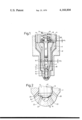
- FIG. 1 is a fragmentary sectional view through the lower portion of a fuel injection nozzle
- FIG. 2 is a magnified sectional view of the nozzle in the area of the valve seat.
- FIG. 1 A nozzle body 1 is held against an only partially shown nozzle holder 3 by a cap nut 2.
- An intermediate plate 4 is arranged between the nozzle body 1 and the nozzle holder 3.
- a valve needle 6 is arranged in a blind bore 5 of the nozzle body 1 so as to be radially sealed and axially movable.
- the valve needle 6 which includes a sealing cone 7 is arranged to rest on a valve seat 8 and defines with its lower frontal side 9 a blind bore 10 disposed in the nozzle body 1 and thus serves as a pressure chamber.
- the valve needle 6 is formed as a slide valve and is guided over most of its entire length in the blind bore 5 of the nozzle body 1.
- annular groove 11 which is connected with the pressure chamber 10 by means of an axially arranged channel 12, which runs through the valve needle 6.
- the annular groove 11, on the other hand, is in continuous communication with an opening 13 of a pressure line 14, which extends through the nozzle holder 3, the intermediate plate 4 and the nozzle body 5.
- a second annular groove 15 is arranged in the outer surface of the valve needle 6, namely between the sealing cone 7 and the annular groove 11. This second annular groove 15, which serves as a pressure block, is relieved of pressure by a relief channel 16.
- the valve needle 6 is loaded by means of a spring 18 which is supported on an annular shoulder provided on plate 17, said spring 18 being arranged in a spring chamber 19 of the needle holder 3.
- the discharge channel 16 opens into spring chamber 19, which is accordingly fully relieved of pressure.
- the support plate 17 for spring 18 strikes a stop ring 20, which in turn supports a second closing spring 21.
- injection openings 22, which are arranged in the nozzle body 1, are arranged in the valve seat 8, with these injection openings 22 adapted to be controlled by the sealing cone 7 of the valve needle 6. Because it is very difficult to maintain a precise covering of the injection openings 22 by the sealing cone 7, as shown in FIG. 2, the slope of the valve cone 7 is greater than that of the valve seat 8. In this manner there results a linear seat 23, which separates the pressure chamber 10 from the injection openings 22.
- annular chamber 24 of a somewhat larger diameter disposed between the cylindrical bore section of the blind bore 5 and its end, so that after the valve needle 6 lifts away from the seat 8 an additional pressure stage is effective.
- the fuel injection nozzle operates in the following manner: As soon as the fuel from the fuel injection pump (not shown) travels through the pressure line 14 and the connecting channel 12 and arrives in the pressure chamber 10, the valve needle 6 is pushed upwardly against the force of the spring 18 until it reaches the stop ring 20. In so doing, the sealing cone 7 lifts away from the valve seat 8 and thereby opens the injection openings 22. At this time fuel also flows into the annular chamber 24. Not until there is a further increase of the fuel pressure is the valve needle 6 then pushed against the spring 18 and the spring 21, until the valve needle strikes the intermediate plate 4 after completion of the entire stroke H 2 by the valve needle. During this strike the injection openings 25, which begin in the inner surface of the bore 5 and lead to the combustion chamber, are opened. In contrast to the injection openings 22, these injection openings 25 are opened by reason of the valve needle 6 sliding upwardly in the nozzle body 1.
- the annular groove 15 serves as a pressure relieving channel.
Abstract
The invention relates to fuel injection nozzles having a bored nozzle body terminating in a blind bore positioned in proximity to a plural series of fuel injection ports one series of which are in communication with a valve seat and arranged to be opened and closed by a slidable valve. The valve needle also includes an axial bore that provides for fuel pressure communication with the blind bore in the nozzle body.
Description
The invention relates to a fuel injection nozzle of the type for use in internal combustion engines provided with an axially movable valve needle, which is radially guided in a blind bore of a nozzle body and is loaded in the normal manner by a closing force. In nozzles of this type the frontal side opposite to the closing force together with a blind bore of the nozzle body defines a pressure chamber, which can be connected with a pressure line that serves to supply fuel to the nozzle. In these nozzles the pressure line extends through the nozzle body and opens into the blind bore and is correlated with the connecting channel. The connection between the pressure chamber and the pressure line is made by a connecting channel that begins in the outer surface of the guided section of the needle and runs through the valve needle. In this known fuel injection nozzle the valve needle is formed in several stages along the section that is guided in the nozzle body, and this has been found to involve difficulties with regard to the seal provided between the valve needle and the nozzle body. While it is relatively simple to match a bore and an element disposed therein that seals as tightly as possible, with multiple stage arrangements of bore and a valve needle it is practically impossible to maintain a desirable seal. While it is common in a simple assembly operation through a selection process to match somewhat larger elements to correspondingly larger bores during machining, this is not possible to be conducted in a satisfactory manner with multiple stage valve needles and nozzle bores. A further disadvantage of these known fuel injection nozzles is that pressurized fuel can flow between the valve needle and the nozzle body to the injection openings, which has the result of substantially decreasing the quality of the exhaust gas.
The invention relates to a fuel injection nozzle in which the valve needle is formed as a shaft and controls fuel injection openings as a slide valve. The pressure chamber is arranged in a blind bore of the nozzle body and is defined by the frontal side of the valve needle and the bore. The fuel supply to the pressure chamber takes place through a connecting channel arranged in the valve needle, the beginning of which connecting channel communicates with the end of the fuel pressure line. An annular groove, which is relieved of pressure, is provided as a pressure block between the pressure chamber and the beginning of the connecting channel on the outer surface of the valve needle.
The fuel injection nozzle according to the invention has the advantage of providing a relatively simple machining operation which produces a valve needle that somewhat resembles a roller that has a V-shaped kerf, with which a high level of sealing is attained in the guided sections between the valve needle and the nozzle body, and that in addition any leakage is avoided by a pressure block.
Another advantage of the present invention is that the nozzle body is provided with an interiorly disposed conical valve seat adjacent to the blind bore and that the valve needle includes a cone-shaped zone for operation with said valve seat.
Still another advantage of this invention is that at least one injection opening extends from the valve seat through the nozzle body to the exterior thereof.
The invention will be better understood as well as further objects and advantages thereof become more apparent from the ensuing detailed description of a preferred embodiment taken in conjunction with the drawing.
FIG. 1 is a fragmentary sectional view through the lower portion of a fuel injection nozzle; and
FIG. 2 is a magnified sectional view of the nozzle in the area of the valve seat.
Turning now to the drawing, the lower portion of a fuel injection nozzle in partial longitudinal section according to the present invention is shown in FIG. 1. A nozzle body 1 is held against an only partially shown nozzle holder 3 by a cap nut 2. An intermediate plate 4 is arranged between the nozzle body 1 and the nozzle holder 3. A valve needle 6 is arranged in a blind bore 5 of the nozzle body 1 so as to be radially sealed and axially movable. The valve needle 6 which includes a sealing cone 7 is arranged to rest on a valve seat 8 and defines with its lower frontal side 9 a blind bore 10 disposed in the nozzle body 1 and thus serves as a pressure chamber.
The valve needle 6 is formed as a slide valve and is guided over most of its entire length in the blind bore 5 of the nozzle body 1. In its exterior surface is arranged an annular groove 11 which is connected with the pressure chamber 10 by means of an axially arranged channel 12, which runs through the valve needle 6. The annular groove 11, on the other hand, is in continuous communication with an opening 13 of a pressure line 14, which extends through the nozzle holder 3, the intermediate plate 4 and the nozzle body 5. In addition, a second annular groove 15 is arranged in the outer surface of the valve needle 6, namely between the sealing cone 7 and the annular groove 11. This second annular groove 15, which serves as a pressure block, is relieved of pressure by a relief channel 16.
The valve needle 6 is loaded by means of a spring 18 which is supported on an annular shoulder provided on plate 17, said spring 18 being arranged in a spring chamber 19 of the needle holder 3. The discharge channel 16 opens into spring chamber 19, which is accordingly fully relieved of pressure. After completion of the first stroke H1 the support plate 17 for spring 18 strikes a stop ring 20, which in turn supports a second closing spring 21.
Referring at this time to FIG. 2, it will be seen that injection openings 22, which are arranged in the nozzle body 1, are arranged in the valve seat 8, with these injection openings 22 adapted to be controlled by the sealing cone 7 of the valve needle 6. Because it is very difficult to maintain a precise covering of the injection openings 22 by the sealing cone 7, as shown in FIG. 2, the slope of the valve cone 7 is greater than that of the valve seat 8. In this manner there results a linear seat 23, which separates the pressure chamber 10 from the injection openings 22. For manufacturing convenience, there is an annular chamber 24 of a somewhat larger diameter disposed between the cylindrical bore section of the blind bore 5 and its end, so that after the valve needle 6 lifts away from the seat 8 an additional pressure stage is effective.
The fuel injection nozzle according to this invention operates in the following manner: As soon as the fuel from the fuel injection pump (not shown) travels through the pressure line 14 and the connecting channel 12 and arrives in the pressure chamber 10, the valve needle 6 is pushed upwardly against the force of the spring 18 until it reaches the stop ring 20. In so doing, the sealing cone 7 lifts away from the valve seat 8 and thereby opens the injection openings 22. At this time fuel also flows into the annular chamber 24. Not until there is a further increase of the fuel pressure is the valve needle 6 then pushed against the spring 18 and the spring 21, until the valve needle strikes the intermediate plate 4 after completion of the entire stroke H2 by the valve needle. During this strike the injection openings 25, which begin in the inner surface of the bore 5 and lead to the combustion chamber, are opened. In contrast to the injection openings 22, these injection openings 25 are opened by reason of the valve needle 6 sliding upwardly in the nozzle body 1.
In order to prevent pressurized fuel other than that from the pressure chamber 10 from passing from the annular groove 11 to the injection openings 25, the annular groove 15 serves as a pressure relieving channel.
The foregoing relates to preferred exemplary embodiments of the invention, it being understood that other embodiments and variants thereof are possible within the spirit and scope of the invention, the latter being defined by the appended claims.
Claims (6)
1. A fuel injection nozzle for internal combustion engines comprising, in combination, a nozzle body having a blind bore, an axially displaceable, shaft-like valve needle radially guided in said nozzle body blind bore, means disposed adjacent the upper end of said valve needle for yieldingly urging said valve needle in a closing direction, the front face of said needle remote from said urging means together with the blind end of said nozzle body blind bore defining a pressure chamber, a pressure line extending within said nozzle body for supplying fuel to the nozzle, a connecting channel extending within the outer surface of said needle for connecting said pressure chamber with said pressure line, said connecting channel beginning in the portion of said needle guided within said blind bore, said pressure line being arranged to discharge fuel into said blind bore opposite the beginning of said connecting channel, said valve needle having the same diameter, representing the largest diameter, at least in the section located between said beginning of said connecting channel and said pressure chamber and a pressure-relieved annular chamber serving as a pressure barrier disposed within said valve needle section.
2. A fuel injection nozzle in accordance with claim 1, including a conical valve seat disposed in said nozzle body between said blind bore and said blind end of said blind bore, said valve needle having a sealing cone which cooperates with said valve seat.
3. A fuel injection nozzle in accordance with claim 2, including at least one injection port disposed within said nozzle body, said at least one injection port having one end opening into said valve seat.
4. A fuel injection nozzle in accordance with claim 3, wherein said valve seat and said sealing cone have a slightly different slope, said valve seat and said sealing cone defining a linear seat extending between said blind end of said blind bore and said at least one injection port.
5. A fuel injection nozzle in accordance with claim 3, including at least one injection port having one opening in the wall of said blind bore, and wherein said valve needle controls with its shaft said at least one injection port in accordance with the stroke of said valve needle.
6. A fuel injection nozzle in accordance with claim 1, wherein said urging means includes a plurality of springs, said plurality of springs being arranged to urge said valve needle in a closing direction in series.
Applications Claiming Priority (2)
| Application Number | Priority Date | Filing Date | Title |
|---|---|---|---|
| DE2711350 | 1977-03-16 | ||
| DE19772711350 DE2711350A1 (en) | 1977-03-16 | 1977-03-16 | FUEL INJECTION NOZZLE FOR COMBUSTION MACHINES |
Publications (1)
| Publication Number | Publication Date |
|---|---|
| US4168804A true US4168804A (en) | 1979-09-25 |
Family
ID=6003728
Family Applications (1)
| Application Number | Title | Priority Date | Filing Date |
|---|---|---|---|
| US05/886,313 Expired - Lifetime US4168804A (en) | 1977-03-16 | 1978-03-13 | Fuel injection nozzle for internal combustion engines |
Country Status (5)
| Country | Link |
|---|---|
| US (1) | US4168804A (en) |
| JP (1) | JPS53113923A (en) |
| DE (1) | DE2711350A1 (en) |
| FR (1) | FR2384124A1 (en) |
| GB (1) | GB1594174A (en) |
Cited By (41)
| Publication number | Priority date | Publication date | Assignee | Title |
|---|---|---|---|---|
| US4275844A (en) * | 1979-11-30 | 1981-06-30 | Caterpillar Tractor Co. | Fuel injection nozzle |
| US4467965A (en) * | 1982-06-19 | 1984-08-28 | Lucas Industries Public Limited Company | Fuel injection nozzles |
| US4537359A (en) * | 1982-10-20 | 1985-08-27 | Lucas Industries, P.L.C. | Fuel injection nozzles |
| US4715541A (en) * | 1985-02-26 | 1987-12-29 | Steyr-Daimler-Puch Ag | Fuel injection nozzle for combustion engines |
| US4715542A (en) * | 1985-03-04 | 1987-12-29 | Steyr-Daimler-Puch Ag | Fuel injection nozzle for internal combustion engines |
| US4758169A (en) * | 1986-02-12 | 1988-07-19 | Sulzer Brothers Limited | Injection valve for reciprocating internal combustion engine |
| US4768719A (en) * | 1985-11-21 | 1988-09-06 | Robert Bosch Gmbh | Fuel injection nozzle for internal combustion engines |
| US4846114A (en) * | 1985-09-16 | 1989-07-11 | Avl Gesellschaft Fur Verbrennungskraftmaschinen Und Messtechnik M.B.H. Prof. Dr.Dr.H.C. Hans List | Method concerning the delivery of fuel into the combustion chamber of a diesel engine and a device for realizing the method |
| US4892065A (en) * | 1985-09-16 | 1990-01-09 | Avl Gesellschaft Fur Verbrennungskraftmaschinen Und Messtechnik M.B.H. Prof. Dr.Dr.H.C. Hans List | Method concerning the delivery of fuel into the combustion chamber of a diesel engine and a device for realizing the method |
| US4899699A (en) * | 1988-03-09 | 1990-02-13 | Chinese Petroleum Company | Low pressure injection system for injecting fuel directly into cylinder of gasoline engine |
| DE3913062A1 (en) * | 1989-04-21 | 1990-10-25 | Daimler Benz Ag | FUEL INJECTION DEVICE FOR AN AIR COMPRESSING INTERNAL COMBUSTION ENGINE, ESPECIALLY SUCH AS A DIRECT INJECTOR |
| US4974571A (en) * | 1989-02-24 | 1990-12-04 | Regents Of The University Of California | Pulsed jet combustion generator for non-premixed charge engines |
| US5242118A (en) * | 1989-08-17 | 1993-09-07 | Steyr-Daimler-Punch Ag | Fuel injector for internal combustion engines |
| US5271565A (en) * | 1992-12-18 | 1993-12-21 | Chrysler Corporation | Fuel injector with valve bounce inhibiting means |
| US5288025A (en) * | 1992-12-18 | 1994-02-22 | Chrysler Corporation | Fuel injector with a hydraulically cushioned valve |
| US5341783A (en) * | 1988-02-03 | 1994-08-30 | Servojet Electronic Systems, Ltd. | Accumulator fuel injection system |
| US5467754A (en) * | 1988-02-03 | 1995-11-21 | Servojet Electronic Systems, Ltd. | Accumulator fuel injection system |
| GB2296039A (en) * | 1994-12-16 | 1996-06-19 | Perkins Ltd | Stress reduction at a high pressure fluid passage junction |
| US5537972A (en) * | 1994-07-28 | 1996-07-23 | Servojet Electronics Systems | Fuel injection system having a pressure intensifier incorporating an overtravel safety feature |
| US5647536A (en) * | 1995-01-23 | 1997-07-15 | Cummins Engine Company, Inc. | Injection rate shaping nozzle assembly for a fuel injector |
| US5899389A (en) * | 1997-06-02 | 1999-05-04 | Cummins Engine Company, Inc. | Two stage fuel injector nozzle assembly |
| US5934571A (en) * | 1996-05-22 | 1999-08-10 | Steyr-Daimler-Puch Aktiengesellschaft | Two-stage fuel-injection nozzle for internal combustion engines |
| US6062497A (en) * | 1996-01-19 | 2000-05-16 | Caterpillar Inc. | Fuel injector nozzle assembly with improved needle check valve stop mechanism |
| WO2001079688A1 (en) * | 2000-04-18 | 2001-10-25 | Robert Bosch Gmbh | Fuel injection valve for internal combustion engines |
| US6378503B1 (en) * | 1999-07-14 | 2002-04-30 | Delphi Technologies, Inc. | Fuel injector |
| WO2002036961A1 (en) * | 2000-11-02 | 2002-05-10 | Siemens Aktiengesellschaft | Injection needle with elastic needle tip |
| US6439483B2 (en) * | 2000-02-10 | 2002-08-27 | Andrew E. Meyer | Variable orifice electronically controlled common rail injector (VOECRRI) |
| US6557776B2 (en) | 2001-07-19 | 2003-05-06 | Cummins Inc. | Fuel injector with injection rate control |
| US20030168526A1 (en) * | 2001-03-12 | 2003-09-11 | Dieter Kienzler | Injection nozzle |
| US6637675B2 (en) | 2001-07-13 | 2003-10-28 | Cummins Inc. | Rate shaping fuel injector with limited throttling |
| US6705543B2 (en) | 2001-08-22 | 2004-03-16 | Cummins Inc. | Variable pressure fuel injection system with dual flow rate injector |
| US20040055562A1 (en) * | 2002-09-25 | 2004-03-25 | Chris Stewart | Mixed mode fuel injector with individually moveable needle valve members |
| US20050224605A1 (en) * | 2004-04-07 | 2005-10-13 | Dingle Philip J | Apparatus and method for mode-switching fuel injector nozzle |
| US20070199544A1 (en) * | 2006-02-28 | 2007-08-30 | Caterpillar Inc. | Fuel injector having recessed check top |
| CN101694199B (en) * | 2009-08-20 | 2011-05-11 | 余姚市舒春机械有限公司 | Nozzle of low-speed diesel engine |
| US20120012681A1 (en) * | 2010-07-15 | 2012-01-19 | Cummins Intellectual Properties, Inc. | Fuel injector having balanced and guided plunger |
| CN102536571A (en) * | 2010-12-06 | 2012-07-04 | Omt都灵机械车间有限公司 | Nozzle with long service life for high-pressure mechanical injectors operating with heavy fuel |
| CN102725511A (en) * | 2009-11-25 | 2012-10-10 | 莱奥林奇有限责任公司 | Fuel injection nozzle for internal combustion engines |
| WO2014022640A1 (en) * | 2012-08-01 | 2014-02-06 | 3M Innovative Properties Company | Fuel injectors with non-coined three-dimensional nozzle inlet face |
| US20160333839A1 (en) * | 2014-01-15 | 2016-11-17 | Continental Automotive Gmbh | Nozzle Assembly and Fuel Injection Valve for a Combustion Engine |
| US10590899B2 (en) | 2012-08-01 | 2020-03-17 | 3M Innovative Properties Company | Fuel injectors with improved coefficient of fuel discharge |
Families Citing this family (18)
| Publication number | Priority date | Publication date | Assignee | Title |
|---|---|---|---|---|
| DE2749379A1 (en) * | 1977-11-04 | 1979-05-10 | Bosch Gmbh Robert | FUEL INJECTOR |
| DE3151293A1 (en) * | 1981-12-24 | 1983-07-07 | Robert Bosch Gmbh, 7000 Stuttgart | FUEL INJECTION SYSTEM FOR DIRECT FUEL INJECTION IN COMBUSTION ENGINES |
| AT378244B (en) * | 1982-12-14 | 1985-07-10 | Steyr Daimler Puch Ag | INJECTION NOZZLE FOR AIR COMPRESSING, SELF-IGNITIONING PISTON PISTON COMBUSTION ENGINES |
| JPS60171958U (en) * | 1984-04-24 | 1985-11-14 | 日産自動車株式会社 | Satsukresu type hole type fuel injection nozzle |
| FR2563826B1 (en) * | 1984-05-07 | 1991-08-30 | Verre Fluore Sa | METHODS OF MANUFACTURING FIBERS AND OPTICAL COMPONENTS IN FLUORINATED GLASSES AND APPARATUSES FOR IMPLEMENTING SAME |
| AT394760B (en) * | 1985-02-26 | 1992-06-25 | Steyr Daimler Puch Ag | Fuel injection nozzle for internal combustion engines |
| AT394761B (en) * | 1985-11-08 | 1992-06-25 | Steyr Daimler Puch Ag | FUEL INJECTION NOZZLE FOR INTERNAL COMBUSTION ENGINES |
| DE3818862C2 (en) * | 1987-06-19 | 1999-01-07 | Volkswagen Ag | Fuel injector |
| JPH081160B2 (en) * | 1988-09-19 | 1996-01-10 | 株式会社ゼクセル | Fuel injection valve |
| GB8912647D0 (en) * | 1989-06-02 | 1989-07-19 | Lucas Ind Plc | Fuel injection nozzles |
| DE3938551A1 (en) * | 1989-11-21 | 1991-05-23 | Bosch Gmbh Robert | IC engine fuel injection nozzle - has longitudinal groove in needle valve stem, delivering fuel to seat |
| JPH04101060A (en) * | 1990-08-16 | 1992-04-02 | Nissan Motor Co Ltd | Direct injection type diesel engine |
| US5211340A (en) * | 1991-08-27 | 1993-05-18 | Zexel Corporation | Fuel injector |
| GB2334755B (en) * | 1996-01-19 | 1999-11-17 | Caterpillar Inc | Fuel injector nozzle assembly with improved needle check valve stop mechanism |
| AT2380U1 (en) * | 1997-08-07 | 1998-09-25 | Avl List Gmbh | INJECTION NOZZLE FOR A DIRECTLY INJECTING INTERNAL COMBUSTION ENGINE |
| DE10124745A1 (en) * | 2001-05-21 | 2003-03-27 | Bosch Gmbh Robert | Fuel injector |
| JP4748045B2 (en) * | 2006-12-01 | 2011-08-17 | 株式会社デンソー | Fuel injection nozzle |
| KR101638815B1 (en) * | 2016-01-07 | 2016-07-25 | 한빛정공(주) | Injection valve for 4 stroke engine |
Citations (3)
| Publication number | Priority date | Publication date | Assignee | Title |
|---|---|---|---|---|
| FR975205A (en) * | 1947-11-18 | 1951-03-02 | Kammer Engines Ltd | Injector |
| DE2014215A1 (en) * | 1970-03-24 | 1971-10-14 | Bergmann, Rolf, 8900 Augsburg | Control of the fuel nozzle |
| US4083498A (en) * | 1975-10-21 | 1978-04-11 | Lucas Industries Limited | Fuel injection nozzles |
Family Cites Families (1)
| Publication number | Priority date | Publication date | Assignee | Title |
|---|---|---|---|---|
| DE971928C (en) * | 1937-05-23 | 1959-04-16 | Max Georg Fiedler | Working method and injection device for diesel engines operated with overload |
-
1977
- 1977-03-16 DE DE19772711350 patent/DE2711350A1/en not_active Withdrawn
-
1978
- 1978-03-13 US US05/886,313 patent/US4168804A/en not_active Expired - Lifetime
- 1978-03-14 FR FR7807354A patent/FR2384124A1/en not_active Withdrawn
- 1978-03-14 JP JP2919678A patent/JPS53113923A/en active Granted
- 1978-03-15 GB GB10185/78A patent/GB1594174A/en not_active Expired
Patent Citations (3)
| Publication number | Priority date | Publication date | Assignee | Title |
|---|---|---|---|---|
| FR975205A (en) * | 1947-11-18 | 1951-03-02 | Kammer Engines Ltd | Injector |
| DE2014215A1 (en) * | 1970-03-24 | 1971-10-14 | Bergmann, Rolf, 8900 Augsburg | Control of the fuel nozzle |
| US4083498A (en) * | 1975-10-21 | 1978-04-11 | Lucas Industries Limited | Fuel injection nozzles |
Cited By (50)
| Publication number | Priority date | Publication date | Assignee | Title |
|---|---|---|---|---|
| US4275844A (en) * | 1979-11-30 | 1981-06-30 | Caterpillar Tractor Co. | Fuel injection nozzle |
| US4467965A (en) * | 1982-06-19 | 1984-08-28 | Lucas Industries Public Limited Company | Fuel injection nozzles |
| US4537359A (en) * | 1982-10-20 | 1985-08-27 | Lucas Industries, P.L.C. | Fuel injection nozzles |
| US4715541A (en) * | 1985-02-26 | 1987-12-29 | Steyr-Daimler-Puch Ag | Fuel injection nozzle for combustion engines |
| US4715542A (en) * | 1985-03-04 | 1987-12-29 | Steyr-Daimler-Puch Ag | Fuel injection nozzle for internal combustion engines |
| US4846114A (en) * | 1985-09-16 | 1989-07-11 | Avl Gesellschaft Fur Verbrennungskraftmaschinen Und Messtechnik M.B.H. Prof. Dr.Dr.H.C. Hans List | Method concerning the delivery of fuel into the combustion chamber of a diesel engine and a device for realizing the method |
| US4892065A (en) * | 1985-09-16 | 1990-01-09 | Avl Gesellschaft Fur Verbrennungskraftmaschinen Und Messtechnik M.B.H. Prof. Dr.Dr.H.C. Hans List | Method concerning the delivery of fuel into the combustion chamber of a diesel engine and a device for realizing the method |
| US4768719A (en) * | 1985-11-21 | 1988-09-06 | Robert Bosch Gmbh | Fuel injection nozzle for internal combustion engines |
| US4758169A (en) * | 1986-02-12 | 1988-07-19 | Sulzer Brothers Limited | Injection valve for reciprocating internal combustion engine |
| US5341783A (en) * | 1988-02-03 | 1994-08-30 | Servojet Electronic Systems, Ltd. | Accumulator fuel injection system |
| US5551391A (en) * | 1988-02-03 | 1996-09-03 | Servojet Electronic Systems, Ltd. | Accumulator fuel injection system |
| US5467754A (en) * | 1988-02-03 | 1995-11-21 | Servojet Electronic Systems, Ltd. | Accumulator fuel injection system |
| US4899699A (en) * | 1988-03-09 | 1990-02-13 | Chinese Petroleum Company | Low pressure injection system for injecting fuel directly into cylinder of gasoline engine |
| US4974571A (en) * | 1989-02-24 | 1990-12-04 | Regents Of The University Of California | Pulsed jet combustion generator for non-premixed charge engines |
| DE3913062A1 (en) * | 1989-04-21 | 1990-10-25 | Daimler Benz Ag | FUEL INJECTION DEVICE FOR AN AIR COMPRESSING INTERNAL COMBUSTION ENGINE, ESPECIALLY SUCH AS A DIRECT INJECTOR |
| US5242118A (en) * | 1989-08-17 | 1993-09-07 | Steyr-Daimler-Punch Ag | Fuel injector for internal combustion engines |
| US5271565A (en) * | 1992-12-18 | 1993-12-21 | Chrysler Corporation | Fuel injector with valve bounce inhibiting means |
| US5288025A (en) * | 1992-12-18 | 1994-02-22 | Chrysler Corporation | Fuel injector with a hydraulically cushioned valve |
| US5537972A (en) * | 1994-07-28 | 1996-07-23 | Servojet Electronics Systems | Fuel injection system having a pressure intensifier incorporating an overtravel safety feature |
| GB2296039A (en) * | 1994-12-16 | 1996-06-19 | Perkins Ltd | Stress reduction at a high pressure fluid passage junction |
| US5647536A (en) * | 1995-01-23 | 1997-07-15 | Cummins Engine Company, Inc. | Injection rate shaping nozzle assembly for a fuel injector |
| US5769319A (en) * | 1995-01-23 | 1998-06-23 | Cummins Engine Company, Inc. | Injection rate shaping nozzle assembly for a fuel injector |
| US6062497A (en) * | 1996-01-19 | 2000-05-16 | Caterpillar Inc. | Fuel injector nozzle assembly with improved needle check valve stop mechanism |
| US5934571A (en) * | 1996-05-22 | 1999-08-10 | Steyr-Daimler-Puch Aktiengesellschaft | Two-stage fuel-injection nozzle for internal combustion engines |
| US5899389A (en) * | 1997-06-02 | 1999-05-04 | Cummins Engine Company, Inc. | Two stage fuel injector nozzle assembly |
| US6378503B1 (en) * | 1999-07-14 | 2002-04-30 | Delphi Technologies, Inc. | Fuel injector |
| US6439483B2 (en) * | 2000-02-10 | 2002-08-27 | Andrew E. Meyer | Variable orifice electronically controlled common rail injector (VOECRRI) |
| WO2001079688A1 (en) * | 2000-04-18 | 2001-10-25 | Robert Bosch Gmbh | Fuel injection valve for internal combustion engines |
| US20030213459A1 (en) * | 2000-11-02 | 2003-11-20 | Thomas Hofmann | Injection needle with flexible needle tip |
| WO2002036961A1 (en) * | 2000-11-02 | 2002-05-10 | Siemens Aktiengesellschaft | Injection needle with elastic needle tip |
| US6871801B2 (en) * | 2001-03-12 | 2005-03-29 | Robert Bosch Gmbh | Injection nozzle |
| US20030168526A1 (en) * | 2001-03-12 | 2003-09-11 | Dieter Kienzler | Injection nozzle |
| US6637675B2 (en) | 2001-07-13 | 2003-10-28 | Cummins Inc. | Rate shaping fuel injector with limited throttling |
| US6557776B2 (en) | 2001-07-19 | 2003-05-06 | Cummins Inc. | Fuel injector with injection rate control |
| US6705543B2 (en) | 2001-08-22 | 2004-03-16 | Cummins Inc. | Variable pressure fuel injection system with dual flow rate injector |
| US20040055562A1 (en) * | 2002-09-25 | 2004-03-25 | Chris Stewart | Mixed mode fuel injector with individually moveable needle valve members |
| US6769635B2 (en) * | 2002-09-25 | 2004-08-03 | Caterpillar Inc | Mixed mode fuel injector with individually moveable needle valve members |
| US20050224605A1 (en) * | 2004-04-07 | 2005-10-13 | Dingle Philip J | Apparatus and method for mode-switching fuel injector nozzle |
| US7415969B2 (en) * | 2006-02-28 | 2008-08-26 | Caterpillar Inc. | Fuel injector having recessed check top |
| US20070199544A1 (en) * | 2006-02-28 | 2007-08-30 | Caterpillar Inc. | Fuel injector having recessed check top |
| CN101694199B (en) * | 2009-08-20 | 2011-05-11 | 余姚市舒春机械有限公司 | Nozzle of low-speed diesel engine |
| CN102725511A (en) * | 2009-11-25 | 2012-10-10 | 莱奥林奇有限责任公司 | Fuel injection nozzle for internal combustion engines |
| CN102725511B (en) * | 2009-11-25 | 2015-10-07 | 莱奥林奇有限责任公司 | For the fuel injection nozzle of internal-combustion engine |
| US20120012681A1 (en) * | 2010-07-15 | 2012-01-19 | Cummins Intellectual Properties, Inc. | Fuel injector having balanced and guided plunger |
| CN102536571A (en) * | 2010-12-06 | 2012-07-04 | Omt都灵机械车间有限公司 | Nozzle with long service life for high-pressure mechanical injectors operating with heavy fuel |
| CN102536571B (en) * | 2010-12-06 | 2014-10-01 | Omt都灵机械车间有限公司 | Nozzle with long service life for high-pressure mechanical injectors operating with heavy fuel |
| WO2014022640A1 (en) * | 2012-08-01 | 2014-02-06 | 3M Innovative Properties Company | Fuel injectors with non-coined three-dimensional nozzle inlet face |
| US10590899B2 (en) | 2012-08-01 | 2020-03-17 | 3M Innovative Properties Company | Fuel injectors with improved coefficient of fuel discharge |
| US20160333839A1 (en) * | 2014-01-15 | 2016-11-17 | Continental Automotive Gmbh | Nozzle Assembly and Fuel Injection Valve for a Combustion Engine |
| US10197034B2 (en) * | 2014-01-15 | 2019-02-05 | Continental Automotive Gmbh | Nozzle assembly and fuel injection valve for a combustion engine |
Also Published As
| Publication number | Publication date |
|---|---|
| JPS53113923A (en) | 1978-10-04 |
| DE2711350A1 (en) | 1978-09-21 |
| FR2384124A1 (en) | 1978-10-13 |
| GB1594174A (en) | 1981-07-30 |
| JPS6137453B2 (en) | 1986-08-23 |
Similar Documents
| Publication | Publication Date | Title |
|---|---|---|
| US4168804A (en) | Fuel injection nozzle for internal combustion engines | |
| US4215821A (en) | Fuel injection nozzle | |
| US4202500A (en) | Multi-hole injection nozzle | |
| US4151958A (en) | Fuel injection nozzle | |
| US4339080A (en) | Fuel injection nozzle | |
| US20040129804A1 (en) | Fuel injection valve for internal combustion engines | |
| US4356976A (en) | Fuel injection nozzle for internal combustion engines | |
| US7117842B2 (en) | Fuel injection valve for internal combustion engines | |
| KR20020027568A (en) | Fuel injection valve for internal combustion engines | |
| US4566635A (en) | Fuel injection nozzle for internal combustion engines | |
| KR20040093064A (en) | Fuel injection valve for internal combustion engines | |
| US4036192A (en) | Engine fuel injection system | |
| US7506635B2 (en) | Fuel injection system | |
| EP0311266B1 (en) | Damped opening poppet covered orifice fuel injection nozzle | |
| US4258883A (en) | Fuel injection nozzle | |
| US3499605A (en) | Nozzle holder | |
| US5950930A (en) | Fuel injection valve for internal combustion engines | |
| US20060202052A1 (en) | Fuel injection valve comprising two coaxial valve needles | |
| US7188790B2 (en) | Fuel-injection valve | |
| US4163521A (en) | Fuel injector | |
| US3403861A (en) | Fuel injection valve for preliminary and main injection | |
| US4641784A (en) | Fuel injection nozzles | |
| US2647015A (en) | Fuel injector | |
| US4216912A (en) | Fuel injection nozzle | |
| US4714198A (en) | Dual fuel single injector nozzle |