US4173281A - Intraocular lens packaging system - Google Patents
Intraocular lens packaging system Download PDFInfo
- Publication number
- US4173281A US4173281A US05/914,800 US91480078A US4173281A US 4173281 A US4173281 A US 4173281A US 91480078 A US91480078 A US 91480078A US 4173281 A US4173281 A US 4173281A
- Authority
- US
- United States
- Prior art keywords
- packaging system
- outer case
- inner case
- intraocular lens
- case
- Prior art date
- Legal status (The legal status is an assumption and is not a legal conclusion. Google has not performed a legal analysis and makes no representation as to the accuracy of the status listed.)
- Expired - Lifetime
Links
Images


Classifications
-
- A—HUMAN NECESSITIES
- A61—MEDICAL OR VETERINARY SCIENCE; HYGIENE
- A61F—FILTERS IMPLANTABLE INTO BLOOD VESSELS; PROSTHESES; DEVICES PROVIDING PATENCY TO, OR PREVENTING COLLAPSING OF, TUBULAR STRUCTURES OF THE BODY, e.g. STENTS; ORTHOPAEDIC, NURSING OR CONTRACEPTIVE DEVICES; FOMENTATION; TREATMENT OR PROTECTION OF EYES OR EARS; BANDAGES, DRESSINGS OR ABSORBENT PADS; FIRST-AID KITS
- A61F2/00—Filters implantable into blood vessels; Prostheses, i.e. artificial substitutes or replacements for parts of the body; Appliances for connecting them with the body; Devices providing patency to, or preventing collapsing of, tubular structures of the body, e.g. stents
- A61F2/02—Prostheses implantable into the body
- A61F2/14—Eye parts, e.g. lenses, corneal implants; Implanting instruments specially adapted therefor; Artificial eyes
- A61F2/16—Intraocular lenses
- A61F2/1691—Packages or dispensers for intraocular lenses
Definitions
- the present invention relates generally to an intraocular lens packaging system, and more particularly to an optically clear sterile intraocular lens packaging system which allows inspection and measurement of the lens without breaking sterility.
- cataracts In the healthy eye, light is focused on the retina by a natural crystalline lens. In certain individuals, the crystalline lens becomes cloudy and opaque, which results in the condition known as a cataract and which results in a loss of vision.
- One method of treating cataracts is the surgical removal of the natural crystalline lens, thereby allowing light to again be received by the retina.
- the light that reaches the retina is unfocused and therefore, normal vision still is impossible. Normal vision is restored by means of artificial lenses, which may be in the form of eyeglasses, contact lenses worn over the cornea or intraocular lenses implanted within the eye itself.
- Intraocular lenses come in a variety of styles and ranges of powers.
- the style of lens is dictated primarily by the preference of the surgeon for any of various surgical procedures for implanting the lens.
- the power of the lens is dictated by the size and shape of the individual eye and whether the lens is fixed anterior or posterior to the iris.
- intraocular lenses are packaged either in dry sterile envelopes with opaque lens cases or sterile transparent tubes with a liquid therein.
- Information as to the power and style of the lens is normally printed on a label affixed to the package.
- prudent surgical practice requires that the surgeon or one of his associates inspect the lens to verify that the labeling information is correct.
- the inspection is normally performed under sterile conditions in the operating room immediately prior to implantation of the lens and involves removing the lens from the package, visually inspecting the lens for style and defects, and measuring the power of the lens with a device known as a lensometer. If it develops that the lens is defective, the lens is normally discarded rather than being repackaged and relabeled, which is a costly and wasteful procedure.
- a further shortcoming of the prior intraocular lens packaging systems lies in maintaining sterility.
- the lens packaging material is brought into the operating room from the outside and therefore the outside thereof is unsterile.
- the prior systems provide no means for assuring sterility of the lens after the systems are opened.
- the lens packaging system includes an outer case having a top and a bottom. At least a portion of the top and bottom of the outer case have optically flat transparent surfaces that are parallel to each other.
- an inner case also having a top and a bottom. At least a portion of the top and bottom of the inner case have optically flat transparent surfaces parallel to each other and parallel to the optically flat transparent surfaces of the other case.
- Means are provided for mounting the lens within the inner case such that the lens lies in a plane parallel to the transparent surfaces of the inner and outer cases. The lens therefore may be inspected from the top to determine the style thereof while the lens is within the packaging system. Additionally, the system can be inserted into a lensometer. Since the optical surfaces of the system are optically flat and transparent and parallel to each other, and parallel to the plane of the lens, the power of the lens can be measured without any refraction from the optical surfaces of the packaging system. Additionally, the resolution of the optical surfaces of the packaging system is greater than that of the lens, thereby making gross inspection of the resolution of the lens possible. Additionally, means are provided for viewing the sides of the lens from the outside of the packaging system thereby allowing complete visual inspection of the lens.
- Means are provided for introducing a sterilizing agent into the packaging system and maintaining the inside thereof sterile while the outisde is unsterile.
- the construction of the packaging system of the present invention allows the system to be brought from the outside into the operating room and opened by a circulating nurse without breaking the sterility of the inner case. If the inner case does inadvertently become contaminated, the construction allows the lens to be removed in a sterile condition.
- FIG. 1 is an exploded perspective view of the preferred embodiment of the lens packaging system of the present invention.
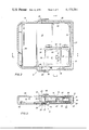
- FIG. 2 is a top partial sectional view of the lens packaging system of the present invention in the assembled condition.
- FIG. 3 is a sectional view along line 3--3 of FIG. 2.
- FIG. 4 is a sectional view taken generally along line 4--4 of FIG. 2.
- FIG. 5 is a fragmented view showing details of the lens mounting means.
- FIG. 6 is a top view taken along line 6--6 of FIG. 5 showing further details of the lens mounting means.
- packaging system 11 is designated generally by the numeral 11 and is adapted to provide an optically clear sterile package for an intraocular lens, designated by the numeral 12, that allows inspection of lens 12 without breaking sterility.
- Packaging system 11 is comprised of an outer case 20, an inner case 30, and means for mounting lens 12 within inner case 30, which in the preferred embodiment includes a mounting tray 40.
- Outer case 20 includes a viewing portion 21 and a cap portion 22.
- viewing portion 21 and cap portion 22 are hollow shells of clear plastic which when joined together form outer case 20.
- Viewing portion 21 and cap portion 22 are joined together by inserting a plug 23 at the open end of viewing portion 21 into a socket 24 at the open end of cap portion 22.
- a plurality of spacer ribs 25 are provided on plug 23 to space the outside of plug 23 apart from the inside of socket 24 to allow the flow of gas into and out of the inside of outer case 20, as will be detailed hereinafter.
- Viewing portion 21 includes a top 26 and a bottom 27, as best shown in FIGS. 3 and 4. At least a portion of top 26 and bottom 27 includes an optically flat surface, which in the preferred embodiment form top window 14 and bottom window 15. Windows 14 and 15 are parallel to each other and overlie each other such that light rays perpendicular to the planes of windows 14 and 15 may pass therethrough without being refracted. Windows 14 and 15 are recessed within top 26 and bottom 27 to prevent their being scratched.
- a side window 16 and an end window 17 are provided in viewing portion 21 of outer case 20.
- Windows 16 and 17 are recessed in similar fashion to windows 14 and 15 and are positioned to allow viewing into the space between windows 14 and 15.
- Inner case 30 is formed of clear plastic and is comprised generally of a bottom 31 hingedly connected to a top 32.
- Bottom 31 has integrally formed therewith a generally square laterally extending flange 33, which serves to position inner case 30 properly within outer case 20 and provides means by which inner case 30 may be inserted into and removed from viewing portion 21.
- Flange 33 also provides space upon which labels and the like may be applied.
- the lower portion of bottom 31 of inner case 30 forms an optically flat lower window 35 and the upper portion of the top 32 of inner case 30 forms an optically flat upper window 36.
- lower window 35 and upper window 36 are parallel to each other.
- a plurality of ribs 38 are provided in the interior of viewing portion 21 of outer case 20 in order to align lower window 35 and upper window 36 of inner case 30 parallel to top window 14 and bottom window 15 of outer case 20, such that light rays may pass through windows 14, 15, 35 and 36, perpendicular to the planes thereof without being refracted.
- Ribs 38 also serve to space apart windows 35 and 36 of inner case 30 from windows 14 and 15 of outer case 20 to prevent scratching thereof and to allow the flow of gas around case 30 and into the interior thereof through a plurality of gas ports 39, as will be detailed hereinafter.
- a side viewing gate 50 and an end viewing gate 51 are provided in bottom 31 of inner case 30.
- a side window 52 and an end window 53 are provided in top 32 of inner case 30, which when put together with side gate 50 and end gate 51 to allow clear viewing from the side and back when inner case 30 is closed.
- Windows 52 and 53 are positioned to coincide with windows 16 and 17 when inner case 30 is inserted into outer case 20.
- Mounting tray 40 is preferably formed of a flexible plastic and is shaped and sized to fit loosely into inner case 30.
- Mounting tray 40 has a flat bottom 41 which overlies lower window 35 of inner case 30 and is parallel thereto.
- At the corners of mounting tray 40 are four spacer posts 42, which serve to keep bottom 41 and lens 12 mounted thereon from contacting upper window 36 when packaging system 11 is inverted.
- Mounting tray 40 has at each end an end viewing gate 43, and at each side a side viewing gate 44. Gates 43 and 44 are positioned to allow clear end and side views of lens 12 from the outside of packaging system 11 when the parts thereof are assembled.
- Lens 12 is mounted upon mounting tray 40 by means of at least a pair of mounting posts 45.
- FIGS. 5 and 6 depict the mounting of a lens 12 having two loops 61 and of the irido capsular style, wherein lens 12 is positioned anterior to the iris and loops 61 pass through the pupil and are fixed within the capsule vacated by the natural crystalline lens.
- Three mounting posts 45 are provided spaced circumferentially about lens 12 at approximately 120° intervals. It will of course be apparent to those skilled in the art that other configurations and spacing of mounting posts would be provided for mounting lens of different styles and that the configuration shown in the drawings is illustrative only.
- Lens 12 is mounted to mounting posts 45 by means of notches 46. Notches 46 are positioned axially along mounting posts 45 equidistant from bottom 41 of mounting tray 40, such that lens 12 lies in a plane parallel to bottom 41.
- mounting tray 40 is preferably of a soft flexible plastic, mounting tray 40 is usually translucent or opaque rather than transparent. Therefore, a circular viewing port 47 is positioned in bottom 41 immediately below lens 12 to allow viewing therethrough. To remove lens 12 from mounting posts 46, mounting tray 40 is simply inverted and finger-tip pressure is applied to the bottom thereof in the vicinity of port 47, whereupon posts 46 spread apart and lens 12 drops free of notches 46.
- a lens 12 of a particular style and with a particular power is manufactured, and the style and power information is recorded on a label applied to flange 33.
- Lens 12 is inserted into notches 46 in mounting posts 45 and mounting tray 40 is deposited into bottom 31 of inner case 30, whereupon top 32 of inner case 30 is closed.
- Inner case 30 is then inserted into viewing portion 21 of outer case 20.
- Flange 30 engages a pair of side shoulders 28 and an end shoulder 29 whereby lens 12 is positioned for viewing through the various windows heretofore described.
- cap 22 With inner case 31 thus inserted into viewing portion 21, cap 22 is fitted over flange 33 such that socket 24 engages plug 23 as shown in FIGS. 2 and 3.
- a groove 55 is provided at the closed end of cap 22, which engages the end of flange 33 to keep the end of socket 24 from engaging the shoulder 70 adjacent to plug 23.
- Shoulder 70 is spaced apart from the end of socket 24 so as to allow the passage of gas into and out of packaging system 11.
- a strip of microporous gas permeable tape is applied around the exterior of socket 24 and shoulder 70 thereby isolating the interior of packaging system 11 from the exterior thereof.
- the porosity of tape 65 is such that gas may pass therethrough but organisms may not.
- packaging system 11 After lens packaging system 11 has been sealed with tape 65, packaging system 11 is placed into a pressure vessel and a vacuum is drawn, which tends to purge the air from the interior of packaging system 11. Viewing port 47, gas ports 39, and ribs 25 and 38 allow free flow of gases within packaging system 11, thereby making system 11 completely purgeable.
- the pressure chamber is pressurized with a sterilizing agent, for example, ethylene oxide gas.
- a sterilizing agent for example, ethylene oxide gas.
- the ethylene oxide gas permeates tape 65 and floods the interior of packaging system 11.
- the ethylene oxide gas kills any organisms within packaging system 11 and thereby sterilizes lens 12.
- the pressure chamber is again evacuated, whereupon the ethylene oxide gas migrates back out of packaging system 11. After substantially all of the ethylene oxide gas has exited system 11, air is allowed to re-enter. Lens packaging system 11 may then be transported to the hospital for use.
- the surgeon or one of his associates can verify in an unsterile environment the correctness of the labeling information with respect to style and optical properties of lens 12.
- Lens 12 may be visually observed through top window 14, side window 16 and end window 17 to determine the style and quality thereof.
- packaging system 11 can be inserted into a lensometer, which measures the focal length of lens 12. Windows 14, 15, 35 and 36, being optically flat and parallel to each other and to the plane of lens 12, do not refract the light passing through lens 12, whereby the lensometer measures only the power of lens 12. After the correctness of the labeling information has been verified, packaging system 11 may be stored for use.
- the surgeon desires to implant lens 12 into an eye, he prescribes the style and optical characteristics that are appropriate for the patient.
- a circulating nurse will then obtain the appropriate lens 12 within lens packaging system 11 from an unsterilized storage area and bring it into the sterilized operating room. Inside the operating room, the circulating nurse removes tape 65 and cap 22, thereby exposing sterilized flange 33. The circulating nurse presents flange 33 to a properly gloved and gowned scrub nurse who removes inner case 30 from viewing portion 21. The scrub nurse then removes mounting tray 40 from inner case 30 and delivers lens 12 to the surgeon for implantation.
- the circulating nurse may carefully open top 32 of inner case 30 and invert inner case 30, allowing mounting tray 40, which is loosely fitted into inner case 30, to fall into the hands of the scrub nurse. The scrub nurse may then proceed to deliver lens 12 to the surgeon for implantation.
- the circulating nurse may remove and invert mounting tray 40 and by the application of finger-tip pressure in the vicinity of view port 47 allow lens 12 to drop into the hands of the scrub nurse, who may then deliver lens 12 to the surgeon for implantation.
- the present invention provides an optically clear sterile intraocular lens packaging system which allows complete inspection of the lens without breaking the sterility thereof.
- the invention further offers maximum safeguards to the sterility of the lens in the transition from an unsterile environment into the operating room.
Abstract
Description
Claims (13)
Priority Applications (1)
| Application Number | Priority Date | Filing Date | Title |
|---|---|---|---|
| US05/914,800 US4173281A (en) | 1978-06-12 | 1978-06-12 | Intraocular lens packaging system |
Applications Claiming Priority (1)
| Application Number | Priority Date | Filing Date | Title |
|---|---|---|---|
| US05/914,800 US4173281A (en) | 1978-06-12 | 1978-06-12 | Intraocular lens packaging system |
Publications (1)
| Publication Number | Publication Date |
|---|---|
| US4173281A true US4173281A (en) | 1979-11-06 |
Family
ID=25434782
Family Applications (1)
| Application Number | Title | Priority Date | Filing Date |
|---|---|---|---|
| US05/914,800 Expired - Lifetime US4173281A (en) | 1978-06-12 | 1978-06-12 | Intraocular lens packaging system |
Country Status (1)
| Country | Link |
|---|---|
| US (1) | US4173281A (en) |
Cited By (37)
| Publication number | Priority date | Publication date | Assignee | Title |
|---|---|---|---|---|
| US4257521A (en) * | 1979-11-16 | 1981-03-24 | Stanley Poler | Packaging means for an intraocular lens |
| US4269307A (en) * | 1979-08-09 | 1981-05-26 | Iolab Corporation | Intraocular lens storage assembly |
| US4402396A (en) * | 1982-02-16 | 1983-09-06 | Cooper Laboratories, Inc. | Intraocular lens case |
| US4406362A (en) * | 1980-10-06 | 1983-09-27 | Ryder International Corporation | Lens carrying case |
| US4508216A (en) * | 1983-07-14 | 1985-04-02 | Kelman Charles D | Housing for an intraocular lens and method of using the same |
| US4545479A (en) * | 1984-08-13 | 1985-10-08 | Figari Alberto A | Contact lens carrying case with magnifying aid apparatus |
| US4615703A (en) * | 1983-07-22 | 1986-10-07 | Cilco, Inc. | Intraocular lens delivery system |
| US4684014A (en) * | 1985-12-09 | 1987-08-04 | American Hospital Supply Corp. | IOL loop retention package and method |
| FR2620687A1 (en) * | 1987-09-23 | 1989-03-24 | Allergan Inc | CONTAINER ASSEMBLY OF A LENS |
| US5171241A (en) * | 1989-06-09 | 1992-12-15 | Ioptex Research Inc. | Device for folding an intraocular lens and holding it in the folded state |
| US5199559A (en) * | 1992-03-16 | 1993-04-06 | Ioptex Research, Inc. | Intraocular lens case |
| US5281227A (en) * | 1992-11-09 | 1994-01-25 | Allergan, Inc. | Lens case with IOL folding device |
| US5396984A (en) * | 1991-06-24 | 1995-03-14 | Procornea Holding B. V. | Container for storing at least one contact lens |
| US5585049A (en) * | 1994-09-02 | 1996-12-17 | Allergan | Method for forming fixation members after optic attachment |
| EP1356791A1 (en) * | 2002-04-01 | 2003-10-29 | Canon-Staar Co., Inc. | Intraocular lens insertion device |
| US20040061828A1 (en) * | 2001-01-31 | 2004-04-01 | Newman Stephen Donald | Soft contact lens capable of engagement with an eye either right way out or inside out |
| US20050143813A1 (en) * | 2003-12-29 | 2005-06-30 | Hovey Larry C. | Universal accommodating iol holder for lens processing and packaging |
| US20050143815A1 (en) * | 2003-12-29 | 2005-06-30 | Jin Wen X. | Lens mounting fixture for accommodating IOL |
| US20060037871A1 (en) * | 2004-08-18 | 2006-02-23 | Jin Wen X | Holder for dual optic IOL |
| US7086526B2 (en) | 2001-08-17 | 2006-08-08 | Clearlab International Pte Ltd. | Packaging for disposable soft contact lenses |
| US20060219577A1 (en) * | 2001-08-17 | 2006-10-05 | Newman Stephen D | Packaging for disposable soft contact lenses |
| US20080011619A1 (en) * | 2002-08-17 | 2008-01-17 | Newman Stephen D | Duo Packaging for Disposable Soft Contact Lenses Using a Substrate |
| US20080146045A1 (en) * | 2006-12-18 | 2008-06-19 | Hon Hai Precision Ind. Co., Ltd. | Electrical connector assembly with protecting |
| CN1982168B (en) * | 2005-12-14 | 2010-05-26 | 鸿富锦精密工业(深圳)有限公司 | Chassis for bearing lens tray |
| US20110024649A1 (en) * | 2009-07-31 | 2011-02-03 | Sciconsult, Inc. | Ophthalmic lens case equipped with an ultraviolet light source |
| US20110214398A1 (en) * | 2010-03-05 | 2011-09-08 | Edwards Lifesciences Corporation | Dry Prosthetic Heart Valve Packaging System |
| US8377125B2 (en) | 2006-04-05 | 2013-02-19 | Anew Optics, Inc. | Intraocular lens with accommodation |
| US8480734B2 (en) | 2007-12-27 | 2013-07-09 | Anew Optics, Inc. | Intraocular lens with accommodation |
| US20130226194A1 (en) * | 2010-07-30 | 2013-08-29 | Procornea Holding B.V. | Device for inserting an intra-ocular lens |
| US20150342730A1 (en) * | 2012-12-20 | 2015-12-03 | Humanoptics Ag | Intraocular lens storage system |
| US9439755B2 (en) | 2008-11-26 | 2016-09-13 | Anew Iol Technologies, Inc. | Haptic devices for intraocular lens |
| US10010405B2 (en) | 2008-11-26 | 2018-07-03 | Anew Aol Technologies, Inc. | Haptic devices for intraocular lens |
| US10264863B2 (en) * | 2017-07-26 | 2019-04-23 | James Gregory Goerges | Tray insert for holding a spectacle lens during transport |
| US20200130921A1 (en) * | 2018-10-26 | 2020-04-30 | Serv Goyal | Bag container system |
| US11267643B2 (en) * | 2019-01-22 | 2022-03-08 | Coopervision International Limited | Contact lens dispenser |
| US20220117850A1 (en) * | 2018-12-27 | 2022-04-21 | Airnov, Inc. | A Tablet Dispensing Device |
| US20220395147A1 (en) * | 2021-06-14 | 2022-12-15 | Angelo Masino | Dispensers and related devices and methods for mounting dispensers |
Citations (5)
| Publication number | Priority date | Publication date | Assignee | Title |
|---|---|---|---|---|
| US2998126A (en) * | 1960-07-11 | 1961-08-29 | Paul W Jenkins | Coin display holder |
| US3155236A (en) * | 1963-02-15 | 1964-11-03 | Billy A Reno | Combined coin holder and exhibitor |
| US3485239A (en) * | 1967-11-02 | 1969-12-23 | Becton Dickinson Co | Self-contained sterile syringe |
| US3837475A (en) * | 1971-11-29 | 1974-09-24 | G Bolanz | Storage device for coins and similar objects |
| US4113088A (en) * | 1977-06-06 | 1978-09-12 | Binkhorst Richard D | Sterile package |
-
1978
- 1978-06-12 US US05/914,800 patent/US4173281A/en not_active Expired - Lifetime
Patent Citations (5)
| Publication number | Priority date | Publication date | Assignee | Title |
|---|---|---|---|---|
| US2998126A (en) * | 1960-07-11 | 1961-08-29 | Paul W Jenkins | Coin display holder |
| US3155236A (en) * | 1963-02-15 | 1964-11-03 | Billy A Reno | Combined coin holder and exhibitor |
| US3485239A (en) * | 1967-11-02 | 1969-12-23 | Becton Dickinson Co | Self-contained sterile syringe |
| US3837475A (en) * | 1971-11-29 | 1974-09-24 | G Bolanz | Storage device for coins and similar objects |
| US4113088A (en) * | 1977-06-06 | 1978-09-12 | Binkhorst Richard D | Sterile package |
Cited By (71)
| Publication number | Priority date | Publication date | Assignee | Title |
|---|---|---|---|---|
| US4269307A (en) * | 1979-08-09 | 1981-05-26 | Iolab Corporation | Intraocular lens storage assembly |
| US4257521A (en) * | 1979-11-16 | 1981-03-24 | Stanley Poler | Packaging means for an intraocular lens |
| US4406362A (en) * | 1980-10-06 | 1983-09-27 | Ryder International Corporation | Lens carrying case |
| US4402396A (en) * | 1982-02-16 | 1983-09-06 | Cooper Laboratories, Inc. | Intraocular lens case |
| US4508216A (en) * | 1983-07-14 | 1985-04-02 | Kelman Charles D | Housing for an intraocular lens and method of using the same |
| US4615703A (en) * | 1983-07-22 | 1986-10-07 | Cilco, Inc. | Intraocular lens delivery system |
| US4545479A (en) * | 1984-08-13 | 1985-10-08 | Figari Alberto A | Contact lens carrying case with magnifying aid apparatus |
| US4684014A (en) * | 1985-12-09 | 1987-08-04 | American Hospital Supply Corp. | IOL loop retention package and method |
| US4928815A (en) * | 1987-09-23 | 1990-05-29 | Allergan, Inc. | Lens container assembly |
| FR2620687A1 (en) * | 1987-09-23 | 1989-03-24 | Allergan Inc | CONTAINER ASSEMBLY OF A LENS |
| US4817789A (en) * | 1987-09-23 | 1989-04-04 | Allergan, Inc. | Lens container assembly |
| US5171241A (en) * | 1989-06-09 | 1992-12-15 | Ioptex Research Inc. | Device for folding an intraocular lens and holding it in the folded state |
| US5396984A (en) * | 1991-06-24 | 1995-03-14 | Procornea Holding B. V. | Container for storing at least one contact lens |
| US5199559A (en) * | 1992-03-16 | 1993-04-06 | Ioptex Research, Inc. | Intraocular lens case |
| US5281227A (en) * | 1992-11-09 | 1994-01-25 | Allergan, Inc. | Lens case with IOL folding device |
| US5585049A (en) * | 1994-09-02 | 1996-12-17 | Allergan | Method for forming fixation members after optic attachment |
| US20040061828A1 (en) * | 2001-01-31 | 2004-04-01 | Newman Stephen Donald | Soft contact lens capable of engagement with an eye either right way out or inside out |
| US7850002B2 (en) | 2001-08-17 | 2010-12-14 | Menicon Co., Ltd. | Packaging for soft contact lenses |
| US7828137B2 (en) | 2001-08-17 | 2010-11-09 | Menicon Co., Ltd. | Packaging for disposable soft contact lenses |
| US20080264804A1 (en) * | 2001-08-17 | 2008-10-30 | Newman Stephen D | Packaging for Soft Contact Lenses |
| US7086526B2 (en) | 2001-08-17 | 2006-08-08 | Clearlab International Pte Ltd. | Packaging for disposable soft contact lenses |
| US20060219577A1 (en) * | 2001-08-17 | 2006-10-05 | Newman Stephen D | Packaging for disposable soft contact lenses |
| EP1356791A1 (en) * | 2002-04-01 | 2003-10-29 | Canon-Staar Co., Inc. | Intraocular lens insertion device |
| CN100341468C (en) * | 2002-04-01 | 2007-10-10 | 佳能星股份有限公司 | Intraocular lens insertion device |
| US8955672B2 (en) | 2002-08-17 | 2015-02-17 | Menicon Singapore Pte Ltd. | Packaging for disposable soft contact lenses |
| US7832552B2 (en) | 2002-08-17 | 2010-11-16 | Menicon Co. Ltd. | Duo packaging for disposable soft contact lenses using a substrate |
| US20060249403A1 (en) * | 2002-08-17 | 2006-11-09 | Newman Stephen D | Packaging for disposable soft contact lenses |
| US20070199832A1 (en) * | 2002-08-17 | 2007-08-30 | Newman Stephen D | Packaging for soft contact lenses |
| US8104608B2 (en) | 2002-08-17 | 2012-01-31 | Menicon Singapore Pte Ltd. | Duo packaging for disposable soft contact lenses using a substrate |
| US20080011619A1 (en) * | 2002-08-17 | 2008-01-17 | Newman Stephen D | Duo Packaging for Disposable Soft Contact Lenses Using a Substrate |
| US8763794B2 (en) | 2002-08-17 | 2014-07-01 | Stephen D. Newman | Packaging for disposable soft contact lenses |
| US9615639B2 (en) | 2002-08-17 | 2017-04-11 | Menicon Singapore Pte Ltd. | Packaging for disposable soft contact lenses |
| US20110162980A1 (en) * | 2002-08-17 | 2011-07-07 | Newman Stephen D | Packaging for disposable soft contact lenses |
| US7461740B2 (en) | 2002-08-17 | 2008-12-09 | Menicon Co., Ltd. | Packaging for soft contact lenses |
| US7967133B2 (en) | 2002-08-17 | 2011-06-28 | Menicon Singapore Pte Ltd. | Packaging for disposable soft contact lenses |
| US20110042243A1 (en) * | 2002-08-17 | 2011-02-24 | Newman Stephen D | Duo packaging for disposable soft contact lenses using a substrate |
| US10786057B2 (en) | 2002-08-17 | 2020-09-29 | Menicon Singapore Pte Ltd. | Packaging for disposable soft contact lenses |
| US20080051801A1 (en) * | 2003-12-29 | 2008-02-28 | Hovey Larry C | Universal Accommodating IOL Holder for Lens Processing and Packaging |
| US20050143815A1 (en) * | 2003-12-29 | 2005-06-30 | Jin Wen X. | Lens mounting fixture for accommodating IOL |
| WO2005065590A1 (en) * | 2003-12-29 | 2005-07-21 | Bausch & Lomb Incorporated | Universal accommodating iol holder for lens processing and packaging |
| US7311194B2 (en) | 2003-12-29 | 2007-12-25 | Bausch & Lomb Incorporated | Lens mounting fixture for accommodating IOL |
| US20050143813A1 (en) * | 2003-12-29 | 2005-06-30 | Hovey Larry C. | Universal accommodating iol holder for lens processing and packaging |
| US7281699B2 (en) | 2003-12-29 | 2007-10-16 | Bausch & Lomb Incorporated | Universal accommodating IOL holder for lens processing and packaging |
| US20060037871A1 (en) * | 2004-08-18 | 2006-02-23 | Jin Wen X | Holder for dual optic IOL |
| CN1982168B (en) * | 2005-12-14 | 2010-05-26 | 鸿富锦精密工业(深圳)有限公司 | Chassis for bearing lens tray |
| US8377125B2 (en) | 2006-04-05 | 2013-02-19 | Anew Optics, Inc. | Intraocular lens with accommodation |
| US7611015B2 (en) * | 2006-12-18 | 2009-11-03 | Hon Hai Precision Ind. Co., Ltd. | Electrical connector assembly with protecting member |
| US20080146045A1 (en) * | 2006-12-18 | 2008-06-19 | Hon Hai Precision Ind. Co., Ltd. | Electrical connector assembly with protecting |
| US8480734B2 (en) | 2007-12-27 | 2013-07-09 | Anew Optics, Inc. | Intraocular lens with accommodation |
| US10010405B2 (en) | 2008-11-26 | 2018-07-03 | Anew Aol Technologies, Inc. | Haptic devices for intraocular lens |
| US9439755B2 (en) | 2008-11-26 | 2016-09-13 | Anew Iol Technologies, Inc. | Haptic devices for intraocular lens |
| US20110024649A1 (en) * | 2009-07-31 | 2011-02-03 | Sciconsult, Inc. | Ophthalmic lens case equipped with an ultraviolet light source |
| US8158961B2 (en) | 2009-07-31 | 2012-04-17 | Sciconsult, Inc. | Ophthalmic lens case equipped with an ultraviolet light source |
| US9539080B2 (en) | 2010-03-05 | 2017-01-10 | Edwards Lifesciences Corporation | Dry prosthetic heart valve packaging system |
| US8679404B2 (en) | 2010-03-05 | 2014-03-25 | Edwards Lifesciences Corporation | Dry prosthetic heart valve packaging system |
| US20110214398A1 (en) * | 2010-03-05 | 2011-09-08 | Edwards Lifesciences Corporation | Dry Prosthetic Heart Valve Packaging System |
| US10561486B2 (en) | 2010-03-05 | 2020-02-18 | Edwards Lifesciences Corporation | Dry prosthetic heart valve packaging system |
| US9937030B2 (en) | 2010-03-05 | 2018-04-10 | Edwards Lifesciences Corporation | Dry prosthetic heart valve packaging system |
| US11911256B2 (en) | 2010-03-05 | 2024-02-27 | Edwards Lifesciences Corporation | Dry prosthetic heart valve packaging system |
| US20130226194A1 (en) * | 2010-07-30 | 2013-08-29 | Procornea Holding B.V. | Device for inserting an intra-ocular lens |
| US9439756B2 (en) * | 2010-07-30 | 2016-09-13 | Oculentis Holding B.V. | Device for inserting an intra-ocular lens |
| US20150342730A1 (en) * | 2012-12-20 | 2015-12-03 | Humanoptics Ag | Intraocular lens storage system |
| US9763775B2 (en) * | 2012-12-20 | 2017-09-19 | Humanoptics Ag | Intraocular lens storage system |
| US10264863B2 (en) * | 2017-07-26 | 2019-04-23 | James Gregory Goerges | Tray insert for holding a spectacle lens during transport |
| US20200130921A1 (en) * | 2018-10-26 | 2020-04-30 | Serv Goyal | Bag container system |
| US20220117850A1 (en) * | 2018-12-27 | 2022-04-21 | Airnov, Inc. | A Tablet Dispensing Device |
| US20220144532A1 (en) * | 2019-01-22 | 2022-05-12 | Coopervision International Limited | Contact Lens Dispenser |
| US11724870B2 (en) * | 2019-01-22 | 2023-08-15 | Coopervision International Limited | Contact lens dispenser |
| US11267643B2 (en) * | 2019-01-22 | 2022-03-08 | Coopervision International Limited | Contact lens dispenser |
| US20220395147A1 (en) * | 2021-06-14 | 2022-12-15 | Angelo Masino | Dispensers and related devices and methods for mounting dispensers |
| US11707163B2 (en) * | 2021-06-14 | 2023-07-25 | Angelo Masino | Dispensers and related devices and methods for mounting dispensers |
Similar Documents
| Publication | Publication Date | Title |
|---|---|---|
| US4173281A (en) | Intraocular lens packaging system | |
| US4113088A (en) | Sterile package | |
| US4269307A (en) | Intraocular lens storage assembly | |
| US4607617A (en) | Apparatus and method for improving eyesight | |
| US4423809A (en) | Packaging system for intraocular lens structures | |
| US4994080A (en) | Optical lens having at least one stenopaeic opening located in the central area thereof | |
| US7712900B2 (en) | Wavefront characterization of corneas | |
| US3440144A (en) | Method and apparatus for checking and testing the effectiveness of sterilization | |
| US5196026A (en) | Method of implanting corneal inlay lenses smaller than the optic zone | |
| US4528268A (en) | Apparatus and method for testing the sufficiency of sterilization | |
| ES2656062T3 (en) | Medical device for preserving a cornea | |
| US20080114386A1 (en) | Method of providing corneal tissue and method of determining the bioburden of laboratory providing same | |
| US20080294149A1 (en) | Corneal Viewing Chamber | |
| JP2004524872A (en) | Apparatus and method for performing eye examination and / or treatment | |
| US6540358B2 (en) | Wavefront characterization of corneas | |
| US20160144454A1 (en) | Enclosure for laser cutting of human tissue | |
| US9737461B2 (en) | Lens holder method | |
| CN104302246B (en) | intracorneal lens | |
| US6286959B1 (en) | Wavefront characterization of corneas | |
| McReynolds et al. | The quick, simple measurement of intraocular lens power and lens resolution at surgery | |
| US20170249871A1 (en) | Training cornea for refractive surgery training | |
| CN103687573A (en) | Corneal implant | |
| US20050148949A1 (en) | Novel instrument for the transplantation of delicate micro-transplants | |
| CN117580548A (en) | Sterile wet packaging and packaging method for hydrophobic intraocular lenses | |
| JP2000175954A (en) | Eyeball fixing ring |
Legal Events
| Date | Code | Title | Description |
|---|---|---|---|
| AS | Assignment |
Owner name: CITIBANK, N.A., AS AGENT Free format text: SECURITY INTEREST;ASSIGNORS:INTERMEDICS, INC.;INTERMEDICS CARDIASSIST, INC.;INTERMEDICS INTRAOCULAR, INC.;AND OTHERS;REEL/FRAME:004303/0077 Effective date: 19840726 Owner name: FIRST NATIONAL BANK OF CHICAGO, THE Free format text: SECURITY INTEREST;ASSIGNORS:INTERMEDICS, INC.;INTERMEDICS CARDIASSIST, INC.;INTERMEDICS INTRAOCULAR, INC.;AND OTHERS;REEL/FRAME:004303/0077 Effective date: 19840726 Owner name: FIRST FREEPORT NATIONAL BANK Free format text: SECURITY INTEREST;ASSIGNORS:INTERMEDICS, INC.;INTERMEDICS CARDIASSIST, INC.;INTERMEDICS INTRAOCULAR, INC.;AND OTHERS;REEL/FRAME:004303/0077 Effective date: 19840726 Owner name: CHASE MANHATTAN BANK, N.A., THE Free format text: SECURITY INTEREST;ASSIGNORS:INTERMEDICS, INC.;INTERMEDICS CARDIASSIST, INC.;INTERMEDICS INTRAOCULAR, INC.;AND OTHERS;REEL/FRAME:004303/0077 Effective date: 19840726 Owner name: BRAZOSPORT BANK OF TEXAS Free format text: SECURITY INTEREST;ASSIGNORS:INTERMEDICS, INC.;INTERMEDICS CARDIASSIST, INC.;INTERMEDICS INTRAOCULAR, INC.;AND OTHERS;REEL/FRAME:004303/0077 Effective date: 19840726 Owner name: TRUST COMPANY BANK Free format text: SECURITY INTEREST;ASSIGNORS:INTERMEDICS, INC.;INTERMEDICS CARDIASSIST, INC.;INTERMEDICS INTRAOCULAR, INC.;AND OTHERS;REEL/FRAME:004303/0077 Effective date: 19840726 Owner name: BANK OF AMERICA NATIONAL TRUST AND SAVINGS ASSOCIA Free format text: SECURITY INTEREST;ASSIGNORS:INTERMEDICS, INC.;INTERMEDICS CARDIASSIST, INC.;INTERMEDICS INTRAOCULAR, INC.;AND OTHERS;REEL/FRAME:004303/0077 Effective date: 19840726 |
|
| AS | Assignment |
Owner name: CITICORP MILTILEASE (SEF), INC. Free format text: SECURITY INTEREST;ASSIGNORS:INTERMEDICS, INC.;INTERMEDICS CARDIASSIST, INC.;INTERMEDICS INTRAOCULAR, INC., A CORP. OF TEXAS;AND OTHERS;REEL/FRAME:004452/0900 Effective date: 19850703 Owner name: B.A. LEASING CORPORATION Free format text: SECURITY INTEREST;ASSIGNORS:INTERMEDICS, INC., A CORP. OF TEXAS;INTERMEDICS CARDIASSIST, INC.;INTERMEDICS INTRAOCULAR, INC., A CORP. OF TEXAS;AND OTHERS;REEL/FRAME:004449/0424 Effective date: 19850703 Owner name: CITIBANK, N.A. Free format text: SECURITY INTEREST;ASSIGNORS:INTERMEDICS, INC., A TX CORP;INTERMEDICS CARDIASSIST, INC., A TX CORP.;INTERMEDICS INTRAOCULAR, INC., A TX CORP.;AND OTHERS;REEL/FRAME:004434/0728 Effective date: 19850703 Owner name: CHASE COMMERCIAL CORPORATION Free format text: SECURITY INTEREST;ASSIGNORS:INTERMEDICS, INC., A CORP. OF TEXAS;INTERMEDICS CARDIASSIST, INC., A CORP OF TX.;INTERMEDICS INTRAOCULAR, INC., A CORP. OF TEXAS;AND OTHERS;REEL/FRAME:004449/0501 Effective date: 19850703 |
|
| AS | Assignment |
Owner name: INTERMEDICS, INC., INTERMEDICS CARDIASSIST, INC., Free format text: SECURED PARTY HEREBY RELEASE THE SECURITY INTEREST IN AGREEMENT RECORDED AUGUST 5, 1985. REEL 4434 FRAMES 728-782;ASSIGNOR:CITIBANK, N.A.;REEL/FRAME:004592/0394 Effective date: 19860502 Owner name: INTERMEDICS, INC. Free format text: RELEASED BY SECURED PARTY;ASSIGNOR:CITICORP MULTILEASE (SEF), INC.;REEL/FRAME:004576/0516 Effective date: 19860515 Owner name: INTERMEDICS, INC., INTERMEDICS CARDIASSIST, INC., Free format text: SAID PARTIES RECITES OBLIGATIONS RECITED IN SECURITY AGREEMENT RECORDED SEPTEMBER 17, 1984 REEL 4303 FRAMES 077-127 HAVE BEEN PAID IN FULL ALL;ASSIGNOR:CITIBANK, N.A., INDIVIDUALLY AND AS AGENT FOR BANK OF AMERICA NATIONAL TRUST AND SAVINGS ASSOCIATION, THE CHASE MANHATTAN BANK, N.A., THE FIRST NATIONAL BANK OF CHICAGO, TRUST COMPANY BANK, FIRST FREEPORT NATIONAL BANK OF BRAZOSPORT BANK OF TEXAS;REEL/FRAME:004592/0424 Effective date: 19860502 |
|
| AS | Assignment |
Owner name: PHARMACIA AB, A SWEDISH CORP. Free format text: ASSIGNMENT OF ASSIGNORS INTEREST.;ASSIGNOR:INTERMEDICS INTRAOCULAR, INC., A DE. CORP.;REEL/FRAME:004688/0946 Effective date: 19861031 Owner name: PHARMACIA AB,SWEDEN Free format text: ASSIGNMENT OF ASSIGNORS INTEREST;ASSIGNOR:INTERMEDICS INTRAOCULAR, INC.;REEL/FRAME:004688/0946 Effective date: 19861031 |