US4182472A - Contactless turning guide for running webs - Google Patents
Contactless turning guide for running webs Download PDFInfo
- Publication number
- US4182472A US4182472A US05/924,160 US92416078A US4182472A US 4182472 A US4182472 A US 4182472A US 92416078 A US92416078 A US 92416078A US 4182472 A US4182472 A US 4182472A
- Authority
- US
- United States
- Prior art keywords
- grooves
- web
- arcuate surface
- barrier
- slot
- Prior art date
- Legal status (The legal status is an assumption and is not a legal conclusion. Google has not performed a legal analysis and makes no representation as to the accuracy of the status listed.)
- Expired - Lifetime
Links
Images


Classifications
-
- B—PERFORMING OPERATIONS; TRANSPORTING
- B65—CONVEYING; PACKING; STORING; HANDLING THIN OR FILAMENTARY MATERIAL
- B65H—HANDLING THIN OR FILAMENTARY MATERIAL, e.g. SHEETS, WEBS, CABLES
- B65H23/00—Registering, tensioning, smoothing or guiding webs
- B65H23/04—Registering, tensioning, smoothing or guiding webs longitudinally
- B65H23/24—Registering, tensioning, smoothing or guiding webs longitudinally by fluid action, e.g. to retard the running web
-
- B—PERFORMING OPERATIONS; TRANSPORTING
- B65—CONVEYING; PACKING; STORING; HANDLING THIN OR FILAMENTARY MATERIAL
- B65H—HANDLING THIN OR FILAMENTARY MATERIAL, e.g. SHEETS, WEBS, CABLES
- B65H2406/00—Means using fluid
- B65H2406/10—Means using fluid made only for exhausting gaseous medium
- B65H2406/11—Means using fluid made only for exhausting gaseous medium producing fluidised bed
- B65H2406/111—Means using fluid made only for exhausting gaseous medium producing fluidised bed for handling material along a curved path, e.g. fluidised turning bar
-
- Y—GENERAL TAGGING OF NEW TECHNOLOGICAL DEVELOPMENTS; GENERAL TAGGING OF CROSS-SECTIONAL TECHNOLOGIES SPANNING OVER SEVERAL SECTIONS OF THE IPC; TECHNICAL SUBJECTS COVERED BY FORMER USPC CROSS-REFERENCE ART COLLECTIONS [XRACs] AND DIGESTS
- Y10—TECHNICAL SUBJECTS COVERED BY FORMER USPC
- Y10S—TECHNICAL SUBJECTS COVERED BY FORMER USPC CROSS-REFERENCE ART COLLECTIONS [XRACs] AND DIGESTS
- Y10S242/00—Winding, tensioning, or guiding
- Y10S242/908—Fluid treatment or handling
Definitions
- the present invention provides a contactless support for a running web in which an arcuate surface is provided and which has a series of parallel grooves in its periphery and that extend in the direction of web travel.
- the contactless support provided by the present invention also includes a pair of air nozzles extending longitudinally of the support member, that is transversely across the web, one such nozzle being located adjacent each of opposite ends of the parallel grooves.
- the air nozzles act to supply pressurized air to the space between the web and the arcuate surface of the support thereby supporting the web in a contactless manner by the pressurized cushion of air.
- the parallel grooves which are formed in the support surface act as labyrinth seals to inhibit the transverse movement of air towards the edges of the running web.
- the particular groove pattern provided by the present invention requires considerably less air flow and air horsepower than conventional arcuate surfaces of the prior art devices, to support the running web in a contactless manner and without marking of the web.
- the arrangement is such that when a web is in moderate to close clearance relationship with the grooved surface of the support, labyrinth seals are created which inhibit transverse air flow from out of the edges of the web.
- a more limited aspect of the invention relates to a barrier which extends transversely of the direction of the web travel and across the grooves and blocks them intermediate their length to thereby form a barrier to the air flow in the grooves.
- This barrier ensures flow stability by preventing one slot from dominating the other which would otherwise lead to a non-symmetrical air flow pattern and reduced cushion pressure as well as result in non-uniform cushion pressure.
- the present invention provides a contactless turning support for a running web in which an arcuate surface has a plurality of parallel grooves in its surface which act as labyrinth seals to provide transverse leakage of air from the air cushion from between the web and the arcuate support.
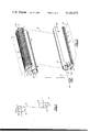
- FIG. 1 is a schematic, elevational view of a web being supported by a pair of contactless supports made in accordance with the present invention
- FIG. 2 is a perspective view of a pair of contactless supports made in accordance with the present invention and as shown schematically in FIG. 1;
- FIG. 3 is an enlarged, cross-sectional view through one of the supports shown in FIG. 2;
- FIG. 4 is a side elevational view of one of the supports shown in FIG. 3 but on a reduced scale
- FIG. 5 is a fragmentary view of the supports shown in FIG. 4 and taken generally along the line 5--5 in FIG. 4.
- FIG. 6 is a transverse cross-sectional view, taken generally along the line 6--6 in FIG. but on an enlarged scale;
- FIG. 7 is a fragmentary perspective view of a portion of the grooved arcuate surface shown, for example, in FIG. 2;
- FIG. 8 is a view similar to FIG. 7 but showing a modification of the barrier in the grooved arcuate surface.
- the web support provided by the present invention can support a running web through various degrees of turning movement, but the present invention has been illustrated as showing a web support for an approximate 90 degree turn of the running web. Such a turning movement is shown in FIG. 1 wherein the web W passes over and without contact with the support S provided by the present invention.
- the support S includes a member 1 formed generally with a 90 degree arcuate surface 2 which extends across the width of the web W to be supported and preferably beyond the edges of the web.
- the support S has shaft means SM by which it is mounted in the machine frame FM.
- a series of parallel grooves 3 are formed in the surface of the arcuate member 1 and extend in the direction of web travel, terminating at 3a at one end and at 3b at the other end. As shown in FIG. 6, the grooves 3 are generally rectangular in cross-sectional shape and form circumferential ribs 4 and also define the upper surface 2 of arcuate form for the support.
- the web W passes a distance away from the surface 2, for example on the order of 1/8 inch, between the web and the slotted surface 2.
- An air nozzle N is located along each of the ends of the grooves 3 and these nozzles extend the full width of the support S; namely, they extend transversely across the width of the web supported by the contactless support S.
- the nozzles are formed by a generally U-shaped piece of metal having a sharp nozzle edge 6 which is spaced a distance from the support 1 so as to define an elongated slot or nozzle 8 through which pressurized air is discharged.
- the nozzle N is held on the frame F of the support by a series of screws 10 at the rear end of the nozzle and also by adjustable screws 12 which are threadably engaged in the frame F and extend freely through the nozzle N so as to adjust the size of the nozzle opening 8.
- the arcuate support S is rigidly secured to the frame member F by the screws 14 and 15 which facilitate the manufacture and assembly of the various parts.
- the nozzle N and the frame F may be all one piece of metal, formed by extrusion, for example.
- the support S includes end plates 16 secured by cap screws 17 to the ends of the arcuate member 1.
- Stub shaft means SM are welded to and extend from the end plates and are adjustably mounted in the frame means FM. The angular position of the support can thus be changed by adjustably rotating the support on its stub shafts.
- the frame F has a series of holes 20 passing therethrough and through which pressurized air is fed from the chamber 24.
- Chamber 24 is also defined by sheet metal members 26 and 28 that in turn are welded to a central duct 30. Air under pressure is supplied to the end of the duct 30 by a supply conduit 31 from an air supply AS.
- the duct 30 has a longitudinal opening 32 and in this manner, pressurized air passes from duct 30 and into the chamber 24, and is readily available for discharge through the nozzle N and to each of the ends of the parallel grooves in the arcuate surface 2.
- a barrier 34 extends transversely of the direction of the web travel and across the grooves 3 and blocks them intermediate their length to thereby form a barrier to the air flow in the grooves.
- the barrier 34 may be formed by being cast if the grooved arcuate support 1 is formed as a casting, or the barrier may be formed by individual pieces inserted in the grooves.
- Another alternative, as shown in FIG. 8, is to form the barrier from a strip of material 34a which is then inserted in an axial slot 35 that is cut through the circumferential ribs 4.
- the barrier eliminates flow instability and prevents one slot from dominating the other which would otherwise result in a non-symmetrical air flow pattern, reduced cushion pressure, and non-uniform cushion pressure.
- pressurized air is introduced between the arcuate support 1 and the web, thus forming a pressurized cushion therebetween which floatingly supports and guides the web as it passes over the arcuate surface 2.
- a clearance is maintained between the web and the arcuate surface 2 of the arcuate support member 1 and by the use of the spaced grooves in the arcuate surface and that extend longitudinally of the web, a labyrinth sealing action is provided which inhibits lateral or transverse flow of air out from the pressurized cushion.
Abstract
Description
Claims (7)
Priority Applications (8)
| Application Number | Priority Date | Filing Date | Title |
|---|---|---|---|
| US05/924,160 US4182472A (en) | 1978-07-13 | 1978-07-13 | Contactless turning guide for running webs |
| SE7905015A SE439473B (en) | 1978-07-13 | 1979-06-08 | CONTROL FOR CONTACT MANAGEMENT OF A CURRENT MATERIAL COURSE |
| CA329,340A CA1078423A (en) | 1978-07-13 | 1979-06-08 | Contactless turning guide for running webs |
| GB7922405A GB2025346B (en) | 1978-07-13 | 1979-06-27 | Contactless turning guide for running web |
| DE2925985A DE2925985C2 (en) | 1978-07-13 | 1979-06-27 | Device for contactless support of a running web |
| FR7916640A FR2430908B1 (en) | 1978-07-13 | 1979-06-27 | DEVICE FOR GUIDING AND RETURNING A TRAVELING STRIP ON A FLUID LAYER AND WITHOUT OTHER CONTACTS |
| IT49633/79A IT1120475B (en) | 1978-07-13 | 1979-07-04 | IMPROVEMENT IN DRIVING SYSTEMS WITHOUT CONTACT OF TAPE MATERIAL ON CURVED ROUTES |
| JP54089210A JPS5839746B2 (en) | 1978-07-13 | 1979-07-13 | web support device |
Applications Claiming Priority (1)
| Application Number | Priority Date | Filing Date | Title |
|---|---|---|---|
| US05/924,160 US4182472A (en) | 1978-07-13 | 1978-07-13 | Contactless turning guide for running webs |
Publications (1)
| Publication Number | Publication Date |
|---|---|
| US4182472A true US4182472A (en) | 1980-01-08 |
Family
ID=25449796
Family Applications (1)
| Application Number | Title | Priority Date | Filing Date |
|---|---|---|---|
| US05/924,160 Expired - Lifetime US4182472A (en) | 1978-07-13 | 1978-07-13 | Contactless turning guide for running webs |
Country Status (8)
| Country | Link |
|---|---|
| US (1) | US4182472A (en) |
| JP (1) | JPS5839746B2 (en) |
| CA (1) | CA1078423A (en) |
| DE (1) | DE2925985C2 (en) |
| FR (1) | FR2430908B1 (en) |
| GB (1) | GB2025346B (en) |
| IT (1) | IT1120475B (en) |
| SE (1) | SE439473B (en) |
Cited By (44)
| Publication number | Priority date | Publication date | Assignee | Title |
|---|---|---|---|---|
| US4282998A (en) * | 1980-05-09 | 1981-08-11 | W. R. Grace & Co. | Maintenance of constant web clearance at contactless turning guide |
| US4288015A (en) * | 1980-02-11 | 1981-09-08 | W. R. Grace & Co. | Contactless web turning guide |
| DE3009325A1 (en) | 1980-03-11 | 1981-09-17 | Vits-Maschinenbau Gmbh, 4018 Langenfeld | Paper diverter between offset printer and drier - supports paper via air cushion, and has pressure roller activated if paper tears by photocell, sensor and air cylinder |
| DE3049790A1 (en) * | 1980-03-11 | 1983-06-16 | Vits-Maschinenbau Gmbh, 4018 Langenfeld | Rotating cylinder used for deflection of ribbon material, has external radial grooves of flat VEE-profile and radial holes are provided at base of these grooves, and two axial edges of box includes flexible strips with axial folds |
| DE3331856A1 (en) * | 1982-09-07 | 1984-03-08 | W.R. Grace & Co., 10036 New York, N.Y. | DEVICE FOR DRYING AND / OR HOLDING RAILWAY MATERIAL |
| US4461432A (en) * | 1980-06-07 | 1984-07-24 | Erwin Kampf Gmbh & Co. Maschinenfabrik | Unwinding apparatus for webs of material, in particular plastic films |
| US4539072A (en) * | 1984-01-31 | 1985-09-03 | Beloit Corporation | Curl neutralizer |
| US4646177A (en) * | 1983-11-25 | 1987-02-24 | Electronic Processors, Inc. | Automatic tape threading system for use in a tape transport system |
| US4696230A (en) * | 1986-09-25 | 1987-09-29 | Barkley Corporation | Adjustable bustle-forming apparatus for maintaining registration of multicolor images on printing webs |
| US4824002A (en) * | 1986-06-06 | 1989-04-25 | Ford John W | Contactless web support guide |
| US4833794A (en) * | 1988-08-10 | 1989-05-30 | Advance Systems, Inc. | Dryer apparatus for floating a running web and having baffle means for spent return air |
| US4904344A (en) * | 1989-04-17 | 1990-02-27 | Beloit Corporation | Automatic web threading apparatus and method |
| US4903907A (en) * | 1988-09-12 | 1990-02-27 | Eastman Kodak Company | Web winding apparatus |
| US4919319A (en) * | 1986-06-06 | 1990-04-24 | Ford John W | Contactless web support guide |
| US4925077A (en) * | 1989-05-04 | 1990-05-15 | Advance Systems, Inc. | Contactless turning guide for running web |
| US5017964A (en) * | 1989-11-29 | 1991-05-21 | Am International, Inc. | Corona charge system and apparatus for electrophotographic printing press |
| US5019868A (en) * | 1989-12-28 | 1991-05-28 | Am International, Inc. | Developer electrode and reverse roller assembly for high speed electrophotographic printing device |
| US5077172A (en) * | 1989-12-28 | 1991-12-31 | Am International, Inc. | Carrier web transfer device and method for electrophotographic printing press |
| EP0506390A1 (en) * | 1991-03-27 | 1992-09-30 | W.R. Grace & Co.-Conn. | Center pivot air turn web steering assembly |
| US5152080A (en) * | 1991-06-25 | 1992-10-06 | W. R. Grace & Co.-Conn. | Steerable air bar/edge dam apparatus |
| US5177877A (en) * | 1989-12-28 | 1993-01-12 | Am International, Inc. | Dryer-fuser apparatus and method for high speed electrophotographic printing device |
| US5284308A (en) * | 1991-04-22 | 1994-02-08 | International Business Machines Corporation | Tape path having implicit squeeze bearing |
| US5358193A (en) * | 1991-10-09 | 1994-10-25 | Minnesota Mining And Manufacturing Company | Tape guide for a data cartridge |
| EP0675064A1 (en) * | 1994-04-01 | 1995-10-04 | W.R. Grace & Co.-Conn. | Air foil wing extension for an air turn |
| US5480086A (en) * | 1988-09-19 | 1996-01-02 | Fuji Photo Film Co., Ltd. | Non-contact web conveying apparatus |
| US5558263A (en) * | 1994-07-26 | 1996-09-24 | Eastman Kodak Company | Apparatus and method for non-contact active tensioning and steering of moving webs |
| US5584441A (en) * | 1995-04-24 | 1996-12-17 | Eastman Kodak Company | Apparatus and method for spooling strips of web into a cartridge |
| US5584442A (en) * | 1995-04-24 | 1996-12-17 | Eastman Kodak Company | Apparatus and method for preparing strips of web and winding them into a cartridge |
| US5597132A (en) * | 1993-02-20 | 1997-01-28 | Basf Magnetics Gmbh | Tape winding device providing uniform winding and rapid installation and removal of winding arm |
| US5979731A (en) * | 1994-10-07 | 1999-11-09 | Eastman Kodak Company | Method and apparatus for preventing creases in thin webs |
| US6078481A (en) * | 1998-06-08 | 2000-06-20 | Imation Corp. | Tape storage cartridge having two-level tape path |
| WO2002044635A2 (en) | 2000-11-28 | 2002-06-06 | Megtec Systems, Inc. | Non-contact floating device for turning a floating web-private |
| US20030188965A1 (en) * | 2002-04-05 | 2003-10-09 | 3M Innovative Properties Company | Web processing method and apparatus |
| SG99320A1 (en) * | 2000-10-27 | 2003-10-27 | Asia Metal Ind Inc | Turning structure of a baking equipment |
| US20050212173A1 (en) * | 2004-03-23 | 2005-09-29 | 3M Innovative Properties Company | Apparatus and method for flexing a web |
| US20050246965A1 (en) * | 2004-03-23 | 2005-11-10 | Swanson Ronald P | Apparatus and method for flexing a web |
| US20080081123A1 (en) * | 2006-09-28 | 2008-04-03 | 3M Innovative Properties Company | System and method for controlling curl in multi-layer webs |
| US20080081164A1 (en) * | 2006-09-28 | 2008-04-03 | 3M Innovative Properties Company | System and method for controlling curl in multi-layer webs |
| US20090155458A1 (en) * | 2006-02-08 | 2009-06-18 | Roehrig Mark A | Method for manufacturing on a film substrate at a temperature above its glass transition |
| US20090252893A1 (en) * | 2005-08-31 | 2009-10-08 | Koji Ozaki | Plasma discharge treatment apparatus, and method of manufacturing gas barrier film |
| KR101021764B1 (en) | 2008-10-07 | 2011-03-17 | 성안기계 (주) | Air turn assembly and flexible web support apparatus having the same |
| US20120111054A1 (en) * | 2010-11-04 | 2012-05-10 | Blanding Douglass L | Methods and Apparatus for Guiding Flexible Glass Ribbons |
| CN106467252A (en) * | 2015-08-14 | 2017-03-01 | 富士胶片株式会社 | Web guide device |
| CN112863760A (en) * | 2021-01-15 | 2021-05-28 | 上海交通大学 | Bundling plate, bundling assembly and preparation device of internally-sealed optical fiber high-temperature superconducting tape |
Families Citing this family (8)
| Publication number | Priority date | Publication date | Assignee | Title |
|---|---|---|---|---|
| DE3479936D1 (en) * | 1983-12-12 | 1989-11-02 | Unisys Corp | Air bearing for moving webs |
| US4750715A (en) * | 1985-07-09 | 1988-06-14 | Mitsubishi Jukogyo Kabushiki Kaisha | Apparatus for cooling steel belt |
| DE3901782A1 (en) * | 1989-01-21 | 1990-08-02 | Breitenbach Ag Bandfabrik | METHOD FOR THE LOW-DISTURBINE TRANSPORT OF TAPE-SHAPED PRODUCTS AND DEVICE THEREFOR |
| US5172844A (en) * | 1989-01-21 | 1992-12-22 | Bandfabrik Breitenbach Ag | Method and apparatus for reducing a transporting strain on elongated material passing through a treatment chamber |
| US5111595A (en) * | 1990-02-21 | 1992-05-12 | W. R. Grace & Co.-Conn. | Chill roll nip |
| WO1992011194A1 (en) * | 1990-12-19 | 1992-07-09 | Eastman Kodak Company | Non-contact web turnbars and reversers with angled holes |
| GB2279489B (en) * | 1993-06-30 | 1997-04-02 | M4 Data Ltd | Tape drive machines |
| DE102011117494A1 (en) * | 2011-10-31 | 2013-05-02 | Eastman Kodak Company | Apparatus and method for printing a substrate web |
Citations (4)
| Publication number | Priority date | Publication date | Assignee | Title |
|---|---|---|---|---|
| US2736106A (en) * | 1956-02-28 | Offen | ||
| US3122295A (en) * | 1962-06-04 | 1964-02-25 | Sylvania Electric Prod | Web transport |
| US3405855A (en) * | 1966-03-11 | 1968-10-15 | Beloit Corp | Paper guide and drive roll assemblies |
| US3521802A (en) * | 1967-05-12 | 1970-07-28 | Masson Scott Thrissell Eng Ltd | Web guide members |
Family Cites Families (4)
| Publication number | Priority date | Publication date | Assignee | Title |
|---|---|---|---|---|
| ES274570A1 (en) * | 1961-02-18 | 1962-10-16 | Svenska Flaektfabriken Ab | Means for turning or reversing the direction of movement of web-shaped material at the end of a run |
| DE1774126B1 (en) * | 1968-04-13 | 1972-07-13 | Vits Maschb Gmbh | Device for stabilizing the position of sheet or arch-shaped workpieces |
| US3567093A (en) * | 1969-06-03 | 1971-03-02 | Michigan Oven Co | Fluid cushion turning roll for moving web |
| GB1307695A (en) * | 1970-08-19 | 1973-02-21 | Ilford Ltd | Air flotation turner bars |
-
1978
- 1978-07-13 US US05/924,160 patent/US4182472A/en not_active Expired - Lifetime
-
1979
- 1979-06-08 SE SE7905015A patent/SE439473B/en unknown
- 1979-06-08 CA CA329,340A patent/CA1078423A/en not_active Expired
- 1979-06-27 GB GB7922405A patent/GB2025346B/en not_active Expired
- 1979-06-27 FR FR7916640A patent/FR2430908B1/en not_active Expired
- 1979-06-27 DE DE2925985A patent/DE2925985C2/en not_active Expired
- 1979-07-04 IT IT49633/79A patent/IT1120475B/en active
- 1979-07-13 JP JP54089210A patent/JPS5839746B2/en not_active Expired
Patent Citations (4)
| Publication number | Priority date | Publication date | Assignee | Title |
|---|---|---|---|---|
| US2736106A (en) * | 1956-02-28 | Offen | ||
| US3122295A (en) * | 1962-06-04 | 1964-02-25 | Sylvania Electric Prod | Web transport |
| US3405855A (en) * | 1966-03-11 | 1968-10-15 | Beloit Corp | Paper guide and drive roll assemblies |
| US3521802A (en) * | 1967-05-12 | 1970-07-28 | Masson Scott Thrissell Eng Ltd | Web guide members |
Cited By (59)
| Publication number | Priority date | Publication date | Assignee | Title |
|---|---|---|---|---|
| US4288015A (en) * | 1980-02-11 | 1981-09-08 | W. R. Grace & Co. | Contactless web turning guide |
| DE3009325A1 (en) | 1980-03-11 | 1981-09-17 | Vits-Maschinenbau Gmbh, 4018 Langenfeld | Paper diverter between offset printer and drier - supports paper via air cushion, and has pressure roller activated if paper tears by photocell, sensor and air cylinder |
| DE3049790A1 (en) * | 1980-03-11 | 1983-06-16 | Vits-Maschinenbau Gmbh, 4018 Langenfeld | Rotating cylinder used for deflection of ribbon material, has external radial grooves of flat VEE-profile and radial holes are provided at base of these grooves, and two axial edges of box includes flexible strips with axial folds |
| US4282998A (en) * | 1980-05-09 | 1981-08-11 | W. R. Grace & Co. | Maintenance of constant web clearance at contactless turning guide |
| US4461432A (en) * | 1980-06-07 | 1984-07-24 | Erwin Kampf Gmbh & Co. Maschinenfabrik | Unwinding apparatus for webs of material, in particular plastic films |
| DE3331856A1 (en) * | 1982-09-07 | 1984-03-08 | W.R. Grace & Co., 10036 New York, N.Y. | DEVICE FOR DRYING AND / OR HOLDING RAILWAY MATERIAL |
| US4646177A (en) * | 1983-11-25 | 1987-02-24 | Electronic Processors, Inc. | Automatic tape threading system for use in a tape transport system |
| US4539072A (en) * | 1984-01-31 | 1985-09-03 | Beloit Corporation | Curl neutralizer |
| US4919319A (en) * | 1986-06-06 | 1990-04-24 | Ford John W | Contactless web support guide |
| US4824002A (en) * | 1986-06-06 | 1989-04-25 | Ford John W | Contactless web support guide |
| US4696230A (en) * | 1986-09-25 | 1987-09-29 | Barkley Corporation | Adjustable bustle-forming apparatus for maintaining registration of multicolor images on printing webs |
| US4833794A (en) * | 1988-08-10 | 1989-05-30 | Advance Systems, Inc. | Dryer apparatus for floating a running web and having baffle means for spent return air |
| US4903907A (en) * | 1988-09-12 | 1990-02-27 | Eastman Kodak Company | Web winding apparatus |
| US5480086A (en) * | 1988-09-19 | 1996-01-02 | Fuji Photo Film Co., Ltd. | Non-contact web conveying apparatus |
| US4904344A (en) * | 1989-04-17 | 1990-02-27 | Beloit Corporation | Automatic web threading apparatus and method |
| US4925077A (en) * | 1989-05-04 | 1990-05-15 | Advance Systems, Inc. | Contactless turning guide for running web |
| US5017964A (en) * | 1989-11-29 | 1991-05-21 | Am International, Inc. | Corona charge system and apparatus for electrophotographic printing press |
| US5019868A (en) * | 1989-12-28 | 1991-05-28 | Am International, Inc. | Developer electrode and reverse roller assembly for high speed electrophotographic printing device |
| US5077172A (en) * | 1989-12-28 | 1991-12-31 | Am International, Inc. | Carrier web transfer device and method for electrophotographic printing press |
| US5177877A (en) * | 1989-12-28 | 1993-01-12 | Am International, Inc. | Dryer-fuser apparatus and method for high speed electrophotographic printing device |
| EP0506390A1 (en) * | 1991-03-27 | 1992-09-30 | W.R. Grace & Co.-Conn. | Center pivot air turn web steering assembly |
| US5284308A (en) * | 1991-04-22 | 1994-02-08 | International Business Machines Corporation | Tape path having implicit squeeze bearing |
| US5152080A (en) * | 1991-06-25 | 1992-10-06 | W. R. Grace & Co.-Conn. | Steerable air bar/edge dam apparatus |
| US5358193A (en) * | 1991-10-09 | 1994-10-25 | Minnesota Mining And Manufacturing Company | Tape guide for a data cartridge |
| US5597132A (en) * | 1993-02-20 | 1997-01-28 | Basf Magnetics Gmbh | Tape winding device providing uniform winding and rapid installation and removal of winding arm |
| EP0675064A1 (en) * | 1994-04-01 | 1995-10-04 | W.R. Grace & Co.-Conn. | Air foil wing extension for an air turn |
| US5558263A (en) * | 1994-07-26 | 1996-09-24 | Eastman Kodak Company | Apparatus and method for non-contact active tensioning and steering of moving webs |
| US5979731A (en) * | 1994-10-07 | 1999-11-09 | Eastman Kodak Company | Method and apparatus for preventing creases in thin webs |
| US5584441A (en) * | 1995-04-24 | 1996-12-17 | Eastman Kodak Company | Apparatus and method for spooling strips of web into a cartridge |
| US5584442A (en) * | 1995-04-24 | 1996-12-17 | Eastman Kodak Company | Apparatus and method for preparing strips of web and winding them into a cartridge |
| US6078481A (en) * | 1998-06-08 | 2000-06-20 | Imation Corp. | Tape storage cartridge having two-level tape path |
| SG99320A1 (en) * | 2000-10-27 | 2003-10-27 | Asia Metal Ind Inc | Turning structure of a baking equipment |
| WO2002044635A2 (en) | 2000-11-28 | 2002-06-06 | Megtec Systems, Inc. | Non-contact floating device for turning a floating web-private |
| US6505792B1 (en) | 2000-11-28 | 2003-01-14 | Megtec Systems, Inc. | Non-contact floating device for turning a floating web |
| US6991717B2 (en) | 2002-04-05 | 2006-01-31 | 3M Innovative Properties Company | Web processing method and apparatus |
| US20030188965A1 (en) * | 2002-04-05 | 2003-10-09 | 3M Innovative Properties Company | Web processing method and apparatus |
| US20060116268A1 (en) * | 2002-04-05 | 2006-06-01 | 3M Innovative Properties Company | Web processing method and apparatus |
| US7399173B2 (en) | 2004-03-23 | 2008-07-15 | 3M Innovative Properties Company | Apparatus for flexing a web |
| US20050246965A1 (en) * | 2004-03-23 | 2005-11-10 | Swanson Ronald P | Apparatus and method for flexing a web |
| US7384586B2 (en) | 2004-03-23 | 2008-06-10 | 3M Innovative Properties Company | Method for flexing a web |
| US20050212173A1 (en) * | 2004-03-23 | 2005-09-29 | 3M Innovative Properties Company | Apparatus and method for flexing a web |
| US20080199552A1 (en) * | 2004-03-23 | 2008-08-21 | 3M Innovative Properties Company | System for flexing a web |
| US7753669B2 (en) | 2004-03-23 | 2010-07-13 | 3M Innovative Properties Company | System for flexing a web |
| US20090252893A1 (en) * | 2005-08-31 | 2009-10-08 | Koji Ozaki | Plasma discharge treatment apparatus, and method of manufacturing gas barrier film |
| EP2278047A1 (en) * | 2005-08-31 | 2011-01-26 | Konica Minolta Holdings, Inc. | Plasma discharge treatment apparatus, and method of manufacturing gas barrier film |
| US8871298B2 (en) | 2006-02-08 | 2014-10-28 | 3M Innovative Properties Company | Method for manufacturing on a film substrate at a temperature above its glass transition |
| US20090155458A1 (en) * | 2006-02-08 | 2009-06-18 | Roehrig Mark A | Method for manufacturing on a film substrate at a temperature above its glass transition |
| US8647556B2 (en) | 2006-09-28 | 2014-02-11 | 3M Innovative Properties Company | System and method for controlling curl in multi-layer webs |
| US7998534B2 (en) | 2006-09-28 | 2011-08-16 | 3M Innovative Properties Company | System and method for controlling curl in multi-layer webs |
| US20080081164A1 (en) * | 2006-09-28 | 2008-04-03 | 3M Innovative Properties Company | System and method for controlling curl in multi-layer webs |
| US20080081123A1 (en) * | 2006-09-28 | 2008-04-03 | 3M Innovative Properties Company | System and method for controlling curl in multi-layer webs |
| US10384231B2 (en) | 2006-09-28 | 2019-08-20 | 3M Innovative Properties Company | System and method for controlling curl in multi-layer webs |
| KR101021764B1 (en) | 2008-10-07 | 2011-03-17 | 성안기계 (주) | Air turn assembly and flexible web support apparatus having the same |
| US20120111054A1 (en) * | 2010-11-04 | 2012-05-10 | Blanding Douglass L | Methods and Apparatus for Guiding Flexible Glass Ribbons |
| KR20120047836A (en) * | 2010-11-04 | 2012-05-14 | 코닝 인코포레이티드 | Methods and apparatus for guiding flexible glass ribbons |
| US9199816B2 (en) * | 2010-11-04 | 2015-12-01 | Corning Incorporated | Methods and apparatus for guiding flexible glass ribbons |
| CN106467252A (en) * | 2015-08-14 | 2017-03-01 | 富士胶片株式会社 | Web guide device |
| CN112863760A (en) * | 2021-01-15 | 2021-05-28 | 上海交通大学 | Bundling plate, bundling assembly and preparation device of internally-sealed optical fiber high-temperature superconducting tape |
| CN112863760B (en) * | 2021-01-15 | 2022-06-28 | 上海交通大学 | Bundling assembly for superconducting tape packaging and inner-packaging optical fiber high-temperature superconducting tape preparation device thereof |
Also Published As
| Publication number | Publication date |
|---|---|
| JPS5839746B2 (en) | 1983-09-01 |
| CA1078423A (en) | 1980-05-27 |
| SE439473B (en) | 1985-06-17 |
| DE2925985C2 (en) | 1986-03-06 |
| GB2025346A (en) | 1980-01-23 |
| IT7949633A0 (en) | 1979-07-04 |
| DE2925985A1 (en) | 1980-01-24 |
| FR2430908A1 (en) | 1980-02-08 |
| JPS5511500A (en) | 1980-01-26 |
| GB2025346B (en) | 1982-08-25 |
| FR2430908B1 (en) | 1986-04-11 |
| IT1120475B (en) | 1986-03-26 |
| SE7905015L (en) | 1980-01-14 |
Similar Documents
| Publication | Publication Date | Title |
|---|---|---|
| US4182472A (en) | Contactless turning guide for running webs | |
| US4197972A (en) | Contactless turning guide having air slots longitudinally along running web edges | |
| US4833794A (en) | Dryer apparatus for floating a running web and having baffle means for spent return air | |
| CA1137528A (en) | Contactless web turning guide | |
| US4197973A (en) | High velocity web floating air bar having air flow straightening means for air discharge slot means | |
| US4043495A (en) | Air cushioned turn bar | |
| US3008366A (en) | Paper perforating mechanism | |
| CA1295478C (en) | Device for stabilizing the run of a meterial web, specifically for stabilizing a paper web in the drying section of a paper machine | |
| GB1340360A (en) | Web stabilizer | |
| US5022166A (en) | Flutter suppression air foils | |
| GB2070570A (en) | Silencing of webs running over fixed guide bars | |
| EP0106428B1 (en) | Web slitting and grooving system | |
| GB2034658A (en) | High velocity web floating air bar having an internal passage for transverse air discharge slot means | |
| US4925077A (en) | Contactless turning guide for running web | |
| EP1337798A2 (en) | Non-contact floating device for turning a floating web-private | |
| US3356067A (en) | Doctor blades having relieved ends | |
| US5242095A (en) | Contactless air turn guide with baffles for running webs | |
| US5252186A (en) | Wire or felt forming section with breast rollers supported by hydrostatic bearings | |
| US6174368B1 (en) | Stationary sliding bar | |
| JP3058880B1 (en) | Turner device | |
| US2839785A (en) | Film advancing roll | |
| US4239141A (en) | Web spreader | |
| US6131847A (en) | Turner bar for a web fed rotary printing machine | |
| US5947411A (en) | Method and apparatus for air flotation | |
| EP0675064A1 (en) | Air foil wing extension for an air turn |
Legal Events
| Date | Code | Title | Description |
|---|---|---|---|
| AS | Assignment |
Owner name: W. R. GRACE & CO.-CONN., MASSACHUSETTS Free format text: MERGER;ASSIGNORS:GRACE MERGER CORP. A CT CORP. (MERGED INTO);W. R. GRACE & CO. A CT. CORP.;REEL/FRAME:005206/0001 Effective date: 19880525 |
|
| AS | Assignment |
Owner name: THERMAL EMISSION CONTROL SYSTEMS, INC., WISCONSIN Free format text: ASSIGNMENT OF ASSIGNORS INTEREST;ASSIGNOR:W.R. GRACE & CO.-CONN.;REEL/FRAME:008820/0146 Effective date: 19970829 Owner name: MEGTEC SYSTEMS, INC., WISCONSIN Free format text: CHANGE OF NAME;ASSIGNOR:THERMAL EMISSION CONTROL SYSTEMS, INC.;REEL/FRAME:008820/0239 Effective date: 19970909 |