US4200297A - Side entry clamp and packoff - Google Patents
Side entry clamp and packoff Download PDFInfo
- Publication number
- US4200297A US4200297A US05/722,540 US72254076A US4200297A US 4200297 A US4200297 A US 4200297A US 72254076 A US72254076 A US 72254076A US 4200297 A US4200297 A US 4200297A
- Authority
- US
- United States
- Prior art keywords
- wireline
- packoff
- housing
- side entry
- sealing element
- Prior art date
- Legal status (The legal status is an assumption and is not a legal conclusion. Google has not performed a legal analysis and makes no representation as to the accuracy of the status listed.)
- Expired - Lifetime
Links
Images


Classifications
-
- E—FIXED CONSTRUCTIONS
- E21—EARTH DRILLING; MINING
- E21B—EARTH DRILLING, e.g. DEEP DRILLING; OBTAINING OIL, GAS, WATER, SOLUBLE OR MELTABLE MATERIALS OR A SLURRY OF MINERALS FROM WELLS
- E21B17/00—Drilling rods or pipes; Flexible drill strings; Kellies; Drill collars; Sucker rods; Cables; Casings; Tubings
- E21B17/02—Couplings; joints
- E21B17/023—Arrangements for connecting cables or wirelines to downhole devices
- E21B17/025—Side entry subs
Definitions
- the present invention relates to a sealing apparatus for a pressurized borehole drilling pipe, and, more particularly, to a side entry clamp and packoff for permitting the sealed and secured side entry of a communication wireline from the outside of a drill pipe section therein.
- Sealing apparatus for borehole drilling operations include structures referred to as "packoff" units for sealingly engaging elements in communication with pressurized members.
- packoffs are often used in drilling apparatus where drilling mud is pumped under pressure down a drill stem to a mud motor which drives a drill bit.
- the mud motor drilling operation is particularly advantageous for a type of borehole construction referred to as controlled drilling wherein the drilling head is directionally controlled to drill both vertically and laterally.
- various forms of packoffs have been found effective in facilitating certain aspects of controlled drilling.
- Controlled drilling by its very definition generally requires directional survey information, since, in order to assure that the intended hole controlled course and destination are achieved, it is necessary to know in which direction the hole is tending at any time.
- the bottom hole position with respect to the top hole position can be calculated from inclination and direction readings taken from a survey tool positioned in the borehole. It is the implementation of the survey tool that frequently requires the assembly of a packoff unit in the borehole apparatus.
- Survey tools have been found to be useful for all forms of drilling, whether controlled or uncontrolled, since each form of drilling is greatly affected by forces which operate upon the drilling head and tend to randomly direct the course of the borehole away from that desired. Variations and hardness of formations, in particular, may cause the course to wander since the drill bit seeks the path of least resistance. Borehole courses are also affected by their reactive torque produced by a rotating drill bit, which operates upon the length of drill pipe and tends to produce a spiral hole. These forces continually affect the drilling operation and may cause deviations from the intended course of the borehole even when the drilling is theoretically controlled.
- a deflection tool known as a "bent sub" which is a substitute section of drill pipe formed with a bend therein and positioned at the lower end of the drill string near the drill bit.
- the primary determinate of the angle at which the drill bit addresses the formation is the degree of bend in the bent sub. In order to turn the hole the entire drill string is merely rotated at the surface to point the bent sub in a different lateral direction.
- attitude indicating, or steering tool instruments adapted for positioning in the borehole to provide directional information.
- These instruments include the gyroscopic, inertial, magnetic and gravitational types.
- Gyroscopic devices utilize the direction maintaining characteristic of a rotating body, while inertial devices, such as accelerometers, sense changes in direction by the principle of inertia.
- Magnetic devices generally use either a magnetic compass or flux gate compass to sense the earth's magnetic field.
- Gravitational devices characteristically use a pendulum to sense the earth's gravity field.
- the position of the attitude indicating devices is detected either photographically, mechanically, electrically or magnetically.
- the key to steering is communicating this information to the surface, wherein the utilization of a packoff generally becomes necessary.
- Attitude sensing devices operate generally in either a drilling "interrupt” or a "while” drilling mode.
- the devices employing electrical or magnetic sensing elements can be used in the "while” drilling mode because of the necessity of transmitting the data up the drill string to the surface.
- the actual transmission from the steering tool is via acoustical transducers which alleviate cumbersome wirelines.
- a "wireline” is preferable. Such wirelines must interconnect steering tools inside the pressurized drill stem with instruments on the surface and outside the drill stem, necessitating a packoff at some point therebetween.
- a conventional and commonly utilized prior art approach to steering through attitude sensing in the "while" drilling mode includes the communication wireline, wherein a cable is threaded through a packoff unit at the surface of the borehole near the end of the drill pipe and suspended through the center thereof.
- the wireline in this manner, connects the steering tool and monitoring instruments at the surface.
- This approach while reliable and effective in steering the drill bit to facilitate true "controlled” drilling, creates other serious procedural and mechanical problems which are directly related to the drilling operation.
- a cable extending through the center of the drill pipe serves to complicate the requisite drilling hardware and the procedural aspect of adding additional sections of pipe which is inherently necessary as the borehole becomes deeper.
- the apparatus of the present invention is especially adapted for drilling with a steering system by providing for a wireline to be suspended along the outside of the drill stem and to enter and be secured therein through a side entry packoff and clamp near the drilling head.
- the present apparatus overcomes many of the disadvantages of the prior art by providing a wireline communication link which enters the borehole through the upwardly moving mudflow which is egressing around the drill stem rather than a surface packoff. It may be seen that the surface packoff is effectively replaced by a "downhole", side entry clamp and packoff, and, the step of pulling the wireline and steering tool out of the hole to add additional drill stem may be eliminated. Since the outside wireline may still serve to connect the steering tool with the surface monitoring equipment, the method and apparatus of the present invention permits an effective "while" drilling steering mode without the major operational disadvantages generally associated therewith.
- the invention relates to apparatus for controlled drilling with a steering system which includes means for positioning a communication wireline along the outside of the drill pipe extending down into the borehole. More particularly, one aspect of the invention includes a side entry packoff positioned in a section of drill pipe with an apertured sidewall, for receiving the wireline therethrough. The apertured section is positioned above a section of drill pipe having a steering tool therein, and, communication between the surface and the steering tool may be provided through the wireline via the packoff in the drill pipe sidewall. In this manner, steering communications may be continuous during drilling operations and additional drill pipe sections may be added at the surface of the borehole without having to disconnect the wireline or pull it out of the existing drill pipe.
- the invention in another aspect, includes a side entry wireline clamp and packoff for providing sealed entry and securement of a wireline in a drill pipe section disposed within a borehole.
- Controlled drilling with a mud motor may be provided therein and mud may be pumped under pressure down a section of drill pipe through the mud motor on the end thereof.
- the mud motor receives its power from the circulating mud which also picks up the drill cuttings and carries them to the surface where the mud and cuttings egress from the borehole.
- the packoff provides for the positioning of the wireline along the outside of the drill pipe in the borehole and an improved method of drilling with a wireline steering system.
- the method of drilling may be of the type disclosed and claimed in co-pending U.S. Patent Application Ser. No. 722,387, filed on 9/13/76, now abandoned, and assigned to the assignee of the present invention under the title "Method of and Apparatus for Drilling With a Steering System".
- the invention includes apparatus for an improved steering system for controlled drilling of a borehole of the type wherein a steering tool is disposed within a section of drill pipe above a mud motor.
- the steering tool is adapted for sensing the attitude of a section of borehole and communicating the attitude information to the surface of the borehole during the operation of the mud motor.
- a section of drill pipe is provided with an apertured sidewall and is adapted for being positioned above the steering tool and in open-ended communication therewith.
- An insertable sealing unit is provided for positioning in the apertured region of the drill pipe.
- a communication wireline extending from the surface of the borehole may lie along the outside of the drill pipe to the point where it extends through the apertured wall of the drill pipe section and the sealing unit therein for communicating with the steering tool contained therebelow. Communication between the surface and the steering tool may thus be provided in a manner permitting the addition and deletion of sections of drill pipe thereabove without affecting the wireline interconnection therebetween.
- the sealing unit may include an expansion element for extension within a housing provided around the inner periphery of the aperture.
- a compressible sealing element of generally toroidal configuration may similarly be provided for circumferential engagement of the wireline and compression therearound upon extension of the expansion element providing the packoff function therefor.
- a set of cable engaging jaws may be provided for rigid clamping of the cable in conjunction with the sealing element, as downhole requirements necessitate.
- the side entry clamp and packoff apparatus of the present invention further facilitates a more effective and efficient controlled drilling operation.
- a conventional controlled drilling operation is stopped for the purpose of adding additional drill pipe, valuable time is consumed in having to pull a wireline and steering tool on the end thereof out of the drill pipe to provide for this function.
- FIG. 1 is a fragmentary, cross-sectional, side-elevational view of a typical directionally drilled borehole and boring apparatus therefor, illustrating relative earth and instrument positioning and one embodiment of a method of and apparatus for drilling a borehole with a steering system constructed in accordance with the principles of the present invention
- FIG. 2 is an enlarged, side-elevational, cross-sectional, fragmentary view of the section of drill pipe in the borehole of FIG. 1 illustrating the relative positioning of the steering tool wireline, and side entry packoff therefor;
- FIGS. 3a and 3b are fragmentary, front and side-elevational views, respectively, of the steering tool string shown in FIG. 2 housed within a section of drill pipe;
- FIG. 4 is an enlarged, cross-sectional, perspective view of the apertured section of drill pipe of FIG. 2, illustrating in more detail one embodiment of a side entry, wireline packoff secured therein;
- FIGS. 5a, 5b and 5c are cross-sectional views of the apertured section of drill pipe of FIG. 4 taken along lines 5a--5a, 5b--5b and 5c--5c, respectively, thereof, for purposes of illustrating one embodiment of the construction of the assembled wireline packoff shown therein;
- FIG. 6 is an enlarged, cross-sectional, perspective view of an apertured section of drill pipe of the type shown in FIG. 4, illustrating in more detail another embodiment of a side entry wireline packoff and clamp secured therein;
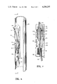
- FIG. 7 is an enlarged, side elevational, cross-sectional view of the wireline clamp and packoff of FIG. 6, taken along the lines 7--7 thereof and illustrating in more detail the construction thereof.
- FIG. 1 there is shown a fragmentary, side-elevational, cross-sectional view of one type of drilling apparatus including a borehole depending therebeneath, with one embodiment of a method of and apparatus for drilling with a steering system provided therein.
- the drilling apparatus as shown for purposes of illustration, includes a derrick structure 10 upstanding from a generally vertically formed borehole 12 which depends from a base surface 14 through a plurality of layers of earth therebeneath.
- the derrick structure 10 is shown in operational support of a type of drilling apparatus generally referred to as the mud motor variety.
- drill pipe 16 interconnected sections of drill pipe 16 are lowered into the borehole 12 for providing viscous mud under pressure to a hydraulic motor housed therein which drives a drilling head, or bit 18, therebelow. Only the drill bit 18 rotates in the mud motor apparatus rather than an entire drill string 19 as in conventional rotary drilling systems. The mud exiting from the drill bit 18 also picks up the borehole cuttings and carries them to the surface of the borehole. A trench 23 is provided at the surface 14 for receiving the mud egressing from the borehole for recirculation. It is in this particular system of drilling that the methods and apparatus of the present invention are particularly applicable.
- the drill string 19 is made up of sections of drill pipe 16 which are securely assembled and interconnected one to the other at the surface 14 before lowering into the borehole 12.
- the standard drill string pipe sections are generally linear, tubular structures with interconnected fittings on both ends.
- Certain pipe sections may, however, have specific modified configurations for providing preselected boring or operational characteristics. It may be seen that such a modified pipe section is provided in a portion of the drill string 19 comprising the angled substitute section 20, commonly referred to as the "bent sub".
- the bent sub is generally positioned above the drill bit 18 for providing a deflection plane which causes the drill bit to bore downwardly through, and laterally from, the theoretically vertical borehole axis.
- a steering tool is positioned preferably in the lower end of the drill string 19 in the general vicinity of the drilling head, as will be discussed in more detail below. It is the requisite function of communicating with the steering tool 21 from the surface 14 that provides the basis of the methods and apparatus of the present invention.
- a cable reel, or drawworks 22 is shown to be provided for feeding a "surface to steering tool” communication wireline, or cable 24, into the borehole.
- the surface end of the cable 24 is connected to an instrument package 26 for receiving and translating the desired cable signals from the borehole 12.
- the lower end of the cable 24 is connected to the steering tool 21 in a manner to be discussed in more detail below.
- the cable 24 of the present invention is provided along the outside of the drill pipe 16 rather than suspended through the center thereof. Provisions are made in the particular embodiment of the invention illustrated herein for the cable 24 to enter the drill pipe 16 near the steering tool 21 through the sidewall of a specially adapted drill pipe section.
- An aperture 25 may thus be seen to be formed longitudinally along the sidewall of the lower drill pipe section 26.
- the aperture 25 is suitably constructed to permit the cable 24 to be received therein in condition for extending through the lower drill pipe section 16 to the steering tool 21 secured therein.
- the cable 24 above the drill pipe section 26 may continually lie undisturbed in the borehole 12 while additional sections of pipe 16 are added at the surface 14.
- the cable 24 provides the requisite communication link between surface and steering tool while utilizing the otherwise conventional steering apparatus of the wireline variety as described herein.
- FIG. 2 there is shown one embodiment of a side entry packoff assembled in position in a section of drill pipe, as will be discussed in detail below. It may also be seen that suitable apparatus is provided for assuring that the rotational position of the steering tool 21 and side entry packoff positioned thereabove is controllably secured.
- the drill string 19 thus preferably includes a mule shoe orienting sub 30 and non-magnetic drill collar 31.
- the steering tool 21 is shown positioned within the interior of the drill collar 31 and is connected at its upper end to the cable 24 which extends up, through, and out the apertured section 26 thereabove.
- the cable 24 therein carries signals generated in the tool 21 to the surface 14 for translation in the instrument package 27.
- Mule shoe orienting sub 30 generally includes a mule shoe sleeve 33 positioned within its interior bore in a predetermined orientation.
- Sleeve 32 is held in the predetermined orientation with the sub by means of a screw, or the like, 34, extending through the sidewall of the sub 30.
- Mule shoe sleeve 32 has a key 36 positioned in its sidewall extending inwardly into the interior bore. The mule shoe sleeve and its key are normally aligned with respect to the deflection plane of the bent sub.
- Mule shoe sleeve 32 has longitudinal slots (not shown) formed therein which provide a mud circulating bypass through the sleeve when the tool 21 is positioned therein.
- a mule shoe 40 is preferably secured to the lower end of the drill string 21 and includes a depending shaft 42 having a tapered end 44 for the guiding thereof into mule sleeve 32.
- a beveled shoulder 46 preferably extends around opposite sides of the prortuding portion 42 meeting at a pointed terminal 48.
- the beveled portions 46 meet to form a longitudinally extending slot 50 sized to receive the inwardly extending key 36 on the mule shoe sleeve 32 when the tool is positioned in the drill pipe 16.
- a hole 52 extends downwardly in the slot toward the center of the tool 21. Hole 52 is arranged to receive a conventional leveling device 54 which has a pin depending therefrom for insertion into the hole.
- the attitude sensing element of the steering tool 21 may include a mule shoe adjuster for permitting rotation of mule shoe 40 relative to the tool string.
- the adjuster may include mating portions such as a conventional T-slot connector (not shown), between mule shoe 40 and tool string 21 to prevent to prevent unwanted relative rotation therebetween.
- a locking collar 56 may also be provided for securing tool string 21 and mule shoe 40 in a fixed relative position.
- FIG. 4 there is shown in a fragmentary, perspective cross-section the apertured region of the wall of the pipe section 26 wherein there is provided a side entry packoff 58 as shown in FIG. 2 and in accordance with one embodiment of the principles of the present invention.
- the packoff 58 is adapted for receiving and sealingly engaging the cable 24 as it is received through the aperture 25.
- the packoff 58 may be seen to provide elongated, side entry means for sealing off the elongate aperture 25 from the center of the drill pipe 16 wherein mud flows under pressure to a mud motor therebelow. It is important to the function of the mud motor drilling apparatus that the drill pipe 16 comprise a closed flow path for the mud from the surface 14 to the drill bit 18.
- the flow path preferably should remain substantially unobstructed. It may be thus seen that the packoff 58 is provided along the outer wall of apertured pipe section 26 to permit a suitable flow path therebehind.
- Such a side entry packoff construction provides for a method of controlled drilling with a steering system as disclosed and claimed in the aforementioned co-pending U.S. Patent application.
- the particular embodiment of the side entry packoff 58 as shown herein is comprised of an elongated, open front housing 60 wherein a separately insertable wireline sealing unit 63 is provided.
- the housing 60 is open through its bottom portion for providing a depending communication passage 62 between the aperture 25 and the flow section of the pipe section 26.
- the housing 60 is securely affixed in sealed engagement to the inside of the pipe section 26 around the inner periphery of the aperture 25 thereof, with the upper end of the housing 60 closed through an upper bulkhead 61 for providing a sealed engagement therewith.
- the cable 24 may be seen to be received from the outside of the drill pipe 16 to the inside region thereof via the aperture 25 and through the sealing unit 63 which includes an elastomeric sealing element 64 positioned in the lower passage 62 of the housing 60. Underlying support of the sealing element 64 is provided by a centrally apertured bulkhead plug 66 adapted for threadably engaging the housing 60 and rigidly securing said sealing element 64 therein. Immediately above the sealing element 64 upstands an expansion structure 68 for providing the requisite wireline receiving and sealing function of the unit 58.
- the expansion structure 68 comprises an apertured spacer 70 having a lower, centrally bored base for receiving the cable 24 therethrough and abutting the sealing element 64 therebetween.
- an extension element 72 Upstanding from the spacer 70 is an extension element 72 including a threaded coupling 74 depending therefrom and engaging the spacer 70 therebeneath.
- the extension element 72 includes a mating head 76 having a cylindrical shoulder 78 which centrally upstands therefrom for mating engagement with a locking recess 80 formed in the upper bulkhead 61 of the housing 60.
- Means are provided for the rotation of the extension element 72 in relation to the stationary spacer unit 70 containing the cable 24 therein.
- Such rotational means preferably includes wrench holes 82 as shown to be provided in the mating head 76 thereof, which wrench holes are adapted for receiving tools for its rotation and its extension upwardly from the spacer 70.
- Suitable locking means are preferably provided for securing the extension of the structure 68 in the housing 60 and the resultant compression of the elastomeric seal 64, which compression seals the cable 24 extending centrally therethrough.
- Such locking means may include a threaded element such as lock nut 84 threadably engaging the threaded coupling 74 depending from the extension element 72 thereabove.
- FIG. 5a illustrating a cross-section of the elastomeric element 64
- the cable 24 extending through the centrally apertured region thereof is circumferentially compressed within the sealing element 64 when said extension element 68 is expanded within the housing 60.
- the housing 60 is securely affixed to the drill pipe 26 by brasing or the like along the outer walls thereof as shown by the fillet 86 therealong.
- the cable 24 freely extends from the spacer 70 through the aperture 25 therealongside.
- the extension element 72 thereabove is similarly centrally apertured for receiving the threaded coupling 74 in the unexpanded condition which condition provides for its insertion into the housing 60 through the aperture 25.
- the packoff unit 58 may thus be seen to function effectively as a side entry sealing apparatus adapted for receiving the cable 24 and the extension thereof for providing the abutting engagement of the cylindrical mating head 78 and the upper bulkhead 61 of the housing 60 causing the axial compression of the sealing element 64 and the select packoff sealing.
- FIGS. 6 and 7 there is shown an alternative embodiment of the side entry packoff 58, as shown in FIG. 4 and in accordance with the principles of the present invention.
- the packoff 58 is similarly adapted for receiving and sealingly engaging a cable 24 as it is received through the aperture 25. It may be seen that the particular embodiment of the packoff as shown herein includes a separate wireline clamping mechanism, apart from the sealing element 64. Moreover, the sealing element is provided against a rigid bulkhead rather than a removable plug as described in more detail below.
- packoff 58 is comprised of an elongated, open front housing 86, wherein a separately insertable wireline clamping and sealing unit 88 is provided.
- the housing 86 is apertured through its bottom portion by passage 90.
- the upper and lower ends of the housing 86 are otherwise through solid bulkheads and the whole structure rigidly secured to the pipe section 26 as set forth above.
- a sealing element 92 may be positioned in the lower portion of the housing 86 for receiving the cable 24 therethrough in sealed engagement therewith.
- Sealing element 92 may be seen to be the structural equivalent of sealing element 64 of FIG. 4, but includes an off-center aperture therethrough as shown in the drawings.
- a compression and clamping structure 94 for providing the requisite wireline receiving, securing, and sealing function of the unit 58.
- Structure 94 is comprised of a generally cylindrical mounting body 96, threaded capping element 98 and gripping jaws 100.
- Mounting body 96 is centrally apertured through a lower passage 102 and an upper mouth 104, centrally aligned one to the other. Mouth 104 is adapted for receiving the gripping jaws 100 therein.
- the capping element 98 is similarly adapted for threaded engagement upon an upper threaded portion 106 of the mounting body 96 and abutting engagement of an upper, slanted end portion 108 of the jaws 100.
- both body 96 and capping element 98 are preferably provided with hexagonal side surfaces for the requisite turning and threaded engagement thereof to provide the desired packoff function.
- the cable 24 is conveniently provided along the outside of the drill stem 19, entering the borehole 12 through the egressing mud flowing into the trench 23 rather than through an expensive packoff unit thereabove.
- the entry of the cable 24 into the drill stem 19 for connection with the steering tool 21 may be provided as desired above said tool and depending on the drilling conditions.
- the sealing packoff unit 58 and/or wireline clamp unit 88 being of the side entry variety facilitate both assembly and disassembly of the steering apparatus without obstructing mud flowing to the mud motor therebelow or extending outwardly of the drill stem as is often the case of conventional packoff and/or clamping units. In this manner additional sections of pipe 16 may be added or removed at the surface 14 without affecting the steering assembly or incurring disadvantageous time loss for the handling thereof.
Abstract
Description
Claims (7)
Priority Applications (1)
| Application Number | Priority Date | Filing Date | Title |
|---|---|---|---|
| US05/722,540 US4200297A (en) | 1976-09-13 | 1976-09-13 | Side entry clamp and packoff |
Applications Claiming Priority (1)
| Application Number | Priority Date | Filing Date | Title |
|---|---|---|---|
| US05/722,540 US4200297A (en) | 1976-09-13 | 1976-09-13 | Side entry clamp and packoff |
Publications (1)
| Publication Number | Publication Date |
|---|---|
| US4200297A true US4200297A (en) | 1980-04-29 |
Family
ID=24902283
Family Applications (1)
| Application Number | Title | Priority Date | Filing Date |
|---|---|---|---|
| US05/722,540 Expired - Lifetime US4200297A (en) | 1976-09-13 | 1976-09-13 | Side entry clamp and packoff |
Country Status (1)
| Country | Link |
|---|---|
| US (1) | US4200297A (en) |
Cited By (39)
| Publication number | Priority date | Publication date | Assignee | Title |
|---|---|---|---|---|
| FR2501777A1 (en) * | 1981-03-13 | 1982-09-17 | Inst Francais Du Petrole | METHOD AND APPARATUS FOR PERFORMING, WITH SPECIALIZED TOOLS, OPERATIONS SUCH AS MEASUREMENTS, IN WELL PORTIONS HIGHLY TILTED ON THE VERTICAL, OR HORIZONTAL |
| FR2502236A1 (en) * | 1981-03-17 | 1982-09-24 | Inst Francais Du Petrole | Tubular connection for drilling string - for introducing flexible line inside the borehole with reduced wear on the line |
| US4379493A (en) * | 1981-05-22 | 1983-04-12 | Gene Thibodeaux | Method and apparatus for preventing wireline kinking in a directional drilling system |
| US4388969A (en) * | 1980-12-01 | 1983-06-21 | Nl Industries, Inc. | Borehole pipe side entry method and apparatus |
| US4399877A (en) * | 1981-04-17 | 1983-08-23 | Nl Sperry Sun, Inc. | Continuous borehole telemetry system and method |
| US4505155A (en) * | 1981-07-13 | 1985-03-19 | Sperry-Sun, Inc. | Borehole pressure measuring system |
| US4506729A (en) * | 1983-02-22 | 1985-03-26 | Exxon Production Research Co. | Drill string sub with self closing cable port valve |
| US4524834A (en) * | 1982-06-22 | 1985-06-25 | Smith International, Inc. | Cablehead side entry sub |
| US4607693A (en) * | 1985-02-11 | 1986-08-26 | Schlumberger Technology Corporation | Side-entry sub |
| US4628995A (en) * | 1985-08-12 | 1986-12-16 | Panex Corporation | Gauge carrier |
| US4674328A (en) * | 1985-07-19 | 1987-06-23 | Dresser Industries, Inc. | Method and apparatus for determining subsurface conditions using a tubing packoff tool |
| US4678038A (en) * | 1986-03-07 | 1987-07-07 | Rankin E Edward | Side entry sub well logging apparatus and method |
| US4681162A (en) * | 1986-02-19 | 1987-07-21 | Boyd's Bit Service, Inc. | Borehole drill pipe continuous side entry or exit apparatus and method |
| US4697638A (en) * | 1986-01-22 | 1987-10-06 | Gearhart Industries, Inc. | Downhole logging and servicing system with manipulatable logging and servicing tools |
| US4699216A (en) * | 1986-08-12 | 1987-10-13 | Rankin E Edward | Blowout preventer for a side entry sub |
| USRE33150E (en) * | 1986-02-19 | 1990-01-23 | Boyd's Bit Service Inc. | Borehole drill pipe continuous side entry or exit apparatus and method |
| US4913227A (en) * | 1987-05-07 | 1990-04-03 | Institut Francais Du Petrole | Equipment for a drill pipe string including a side entry sub, a safety member for anchoring a cable on a support, and a method of using the equipment |
| US4986350A (en) * | 1989-02-09 | 1991-01-22 | Institut Francais Du Petrole | Device for the seismic monitoring of an underground deposit |
| FR2663978A1 (en) * | 1990-06-29 | 1992-01-03 | Elf Aquitaine | PRODUCTION TUBE WITH INTEGRATED HYDRAULIC LINE. |
| US5080168A (en) * | 1989-10-11 | 1992-01-14 | Institut Francais Du Petrole | Device for locking a cable passing across the wall of a tube such as a side-entry sub |
| US5284210A (en) * | 1993-02-04 | 1994-02-08 | Helms Charles M | Top entry sub arrangement |
| WO1994025726A1 (en) * | 1993-04-29 | 1994-11-10 | Moore Boyd B | Seal electrical conductor arrangement for use with a well bore in hazardous areas |
| US5435395A (en) * | 1994-03-22 | 1995-07-25 | Halliburton Company | Method for running downhole tools and devices with coiled tubing |
| US5467826A (en) * | 1994-09-30 | 1995-11-21 | Marathon Oil Company | Oilfield tubing string integrally enclosing a fluid production or injection tube and a service line |
| US5626190A (en) * | 1991-02-06 | 1997-05-06 | Moore; Boyd B. | Apparatus for protecting electrical connection from moisture in a hazardous area adjacent a wellhead barrier for an underground well |
| US5642780A (en) * | 1991-02-06 | 1997-07-01 | Moore; Boyd B. | Stand off for electrical connection in an underground well |
| US5667008A (en) * | 1991-02-06 | 1997-09-16 | Quick Connectors, Inc. | Seal electrical conductor arrangement for use with a well bore in hazardous areas |
| US5810088A (en) * | 1997-03-26 | 1998-09-22 | Baker Hughes, Inc. | Electrically actuated disconnect apparatus and method |
| US6655452B2 (en) * | 2001-09-21 | 2003-12-02 | Fred Zillinger | Downhole gauge carrier apparatus |
| US20040144571A1 (en) * | 2003-01-28 | 2004-07-29 | Boyd's Bit Service, Inc. | Locking swivel apparatus with a supplemental internal locking mechanism |
| US20040144567A1 (en) * | 2003-01-28 | 2004-07-29 | Boyd's Bit Service, Inc. | Locking swivel apparatus with replaceable internal gear members |
| US7261155B1 (en) * | 2004-08-23 | 2007-08-28 | Varco I/P | Cable side-entry sub with grease injection flow tubes |
| US20120043726A1 (en) * | 2010-08-20 | 2012-02-23 | Smith International, Inc. | Multiple sealing element assembly |
| US20140054358A1 (en) * | 2007-04-30 | 2014-02-27 | Mark Andreychuk | Coiled tubing with heat resistant conduit |
| US9194512B2 (en) | 2007-04-30 | 2015-11-24 | Mark Andreychuk | Coiled tubing with heat resistant conduit |
| US20150354302A1 (en) * | 2014-06-09 | 2015-12-10 | Suncor Energy Inc. | Well instrumentation deployment past a downhole tool for in situ hydrocarbon recovery operations |
| CN107120072A (en) * | 2016-02-25 | 2017-09-01 | 中国石油化工股份有限公司 | A kind of steel pipe type cable traversing device |
| WO2018111689A1 (en) * | 2016-12-12 | 2018-06-21 | Shell Oil Company | Method and assembly for downhole deployment of well instrumentation |
| US20180371862A1 (en) * | 2016-09-15 | 2018-12-27 | Halliburton Energy Services, Inc. | Downhole wire routing |
Citations (3)
| Publication number | Priority date | Publication date | Assignee | Title |
|---|---|---|---|---|
| US2355342A (en) * | 1942-06-13 | 1944-08-08 | Carl W Van Wormer | Drilling apparatus |
| US3265398A (en) * | 1963-07-25 | 1966-08-09 | Crane Co | Fabricated stuffing box with gland eye-bolt arrangement |
| US3369618A (en) * | 1964-07-06 | 1968-02-20 | Moore Buell | Well drilling apparatus |
-
1976
- 1976-09-13 US US05/722,540 patent/US4200297A/en not_active Expired - Lifetime
Patent Citations (3)
| Publication number | Priority date | Publication date | Assignee | Title |
|---|---|---|---|---|
| US2355342A (en) * | 1942-06-13 | 1944-08-08 | Carl W Van Wormer | Drilling apparatus |
| US3265398A (en) * | 1963-07-25 | 1966-08-09 | Crane Co | Fabricated stuffing box with gland eye-bolt arrangement |
| US3369618A (en) * | 1964-07-06 | 1968-02-20 | Moore Buell | Well drilling apparatus |
Cited By (55)
| Publication number | Priority date | Publication date | Assignee | Title |
|---|---|---|---|---|
| US4388969A (en) * | 1980-12-01 | 1983-06-21 | Nl Industries, Inc. | Borehole pipe side entry method and apparatus |
| FR2501777A1 (en) * | 1981-03-13 | 1982-09-17 | Inst Francais Du Petrole | METHOD AND APPARATUS FOR PERFORMING, WITH SPECIALIZED TOOLS, OPERATIONS SUCH AS MEASUREMENTS, IN WELL PORTIONS HIGHLY TILTED ON THE VERTICAL, OR HORIZONTAL |
| FR2502236A1 (en) * | 1981-03-17 | 1982-09-24 | Inst Francais Du Petrole | Tubular connection for drilling string - for introducing flexible line inside the borehole with reduced wear on the line |
| US4399877A (en) * | 1981-04-17 | 1983-08-23 | Nl Sperry Sun, Inc. | Continuous borehole telemetry system and method |
| US4379493A (en) * | 1981-05-22 | 1983-04-12 | Gene Thibodeaux | Method and apparatus for preventing wireline kinking in a directional drilling system |
| US4505155A (en) * | 1981-07-13 | 1985-03-19 | Sperry-Sun, Inc. | Borehole pressure measuring system |
| US4524834A (en) * | 1982-06-22 | 1985-06-25 | Smith International, Inc. | Cablehead side entry sub |
| US4506729A (en) * | 1983-02-22 | 1985-03-26 | Exxon Production Research Co. | Drill string sub with self closing cable port valve |
| US4607693A (en) * | 1985-02-11 | 1986-08-26 | Schlumberger Technology Corporation | Side-entry sub |
| US4674328A (en) * | 1985-07-19 | 1987-06-23 | Dresser Industries, Inc. | Method and apparatus for determining subsurface conditions using a tubing packoff tool |
| US4628995A (en) * | 1985-08-12 | 1986-12-16 | Panex Corporation | Gauge carrier |
| US4697638A (en) * | 1986-01-22 | 1987-10-06 | Gearhart Industries, Inc. | Downhole logging and servicing system with manipulatable logging and servicing tools |
| US4681162A (en) * | 1986-02-19 | 1987-07-21 | Boyd's Bit Service, Inc. | Borehole drill pipe continuous side entry or exit apparatus and method |
| USRE33150E (en) * | 1986-02-19 | 1990-01-23 | Boyd's Bit Service Inc. | Borehole drill pipe continuous side entry or exit apparatus and method |
| US4678038A (en) * | 1986-03-07 | 1987-07-07 | Rankin E Edward | Side entry sub well logging apparatus and method |
| US4790377A (en) * | 1986-03-07 | 1988-12-13 | Halliburton Company | Side entry sub well logging apparatus and method |
| US4884632A (en) * | 1986-03-07 | 1989-12-05 | Halliburton Logging Services, Inc. | Side entry sub well logging apparatus and method |
| US4699216A (en) * | 1986-08-12 | 1987-10-13 | Rankin E Edward | Blowout preventer for a side entry sub |
| US4913227A (en) * | 1987-05-07 | 1990-04-03 | Institut Francais Du Petrole | Equipment for a drill pipe string including a side entry sub, a safety member for anchoring a cable on a support, and a method of using the equipment |
| EP0297899A1 (en) * | 1987-07-01 | 1989-01-04 | Halliburton Company | Apparatus and method for releasing a side entry sub |
| US4986350A (en) * | 1989-02-09 | 1991-01-22 | Institut Francais Du Petrole | Device for the seismic monitoring of an underground deposit |
| US5080168A (en) * | 1989-10-11 | 1992-01-14 | Institut Francais Du Petrole | Device for locking a cable passing across the wall of a tube such as a side-entry sub |
| FR2663978A1 (en) * | 1990-06-29 | 1992-01-03 | Elf Aquitaine | PRODUCTION TUBE WITH INTEGRATED HYDRAULIC LINE. |
| WO1992000437A1 (en) * | 1990-06-29 | 1992-01-09 | Societe Nationale Elf Aquitaine (Production) | Production pipe having an integrated hydraulic line |
| US5217071A (en) * | 1990-06-29 | 1993-06-08 | Societe Nationale Elf Aquitaine (Production) | Production tube with integrated hydraulic line |
| US5732771A (en) * | 1991-02-06 | 1998-03-31 | Moore; Boyd B. | Protective sheath for protecting and separating a plurality of insulated cable conductors for an underground well |
| US5823256A (en) * | 1991-02-06 | 1998-10-20 | Moore; Boyd B. | Ferrule--type fitting for sealing an electrical conduit in a well head barrier |
| US5626190A (en) * | 1991-02-06 | 1997-05-06 | Moore; Boyd B. | Apparatus for protecting electrical connection from moisture in a hazardous area adjacent a wellhead barrier for an underground well |
| US5642780A (en) * | 1991-02-06 | 1997-07-01 | Moore; Boyd B. | Stand off for electrical connection in an underground well |
| US5667008A (en) * | 1991-02-06 | 1997-09-16 | Quick Connectors, Inc. | Seal electrical conductor arrangement for use with a well bore in hazardous areas |
| US5667009A (en) * | 1991-02-06 | 1997-09-16 | Moore; Boyd B. | Rubber boots for electrical connection for down hole well |
| US5284210A (en) * | 1993-02-04 | 1994-02-08 | Helms Charles M | Top entry sub arrangement |
| USRE39509E1 (en) * | 1993-02-04 | 2007-03-13 | Specialty Rental Tools & Supply, Lp | Top entry sub arrangement |
| WO1994025726A1 (en) * | 1993-04-29 | 1994-11-10 | Moore Boyd B | Seal electrical conductor arrangement for use with a well bore in hazardous areas |
| US5435395A (en) * | 1994-03-22 | 1995-07-25 | Halliburton Company | Method for running downhole tools and devices with coiled tubing |
| US5467826A (en) * | 1994-09-30 | 1995-11-21 | Marathon Oil Company | Oilfield tubing string integrally enclosing a fluid production or injection tube and a service line |
| US5810088A (en) * | 1997-03-26 | 1998-09-22 | Baker Hughes, Inc. | Electrically actuated disconnect apparatus and method |
| US6655452B2 (en) * | 2001-09-21 | 2003-12-02 | Fred Zillinger | Downhole gauge carrier apparatus |
| US20040144571A1 (en) * | 2003-01-28 | 2004-07-29 | Boyd's Bit Service, Inc. | Locking swivel apparatus with a supplemental internal locking mechanism |
| US20040144567A1 (en) * | 2003-01-28 | 2004-07-29 | Boyd's Bit Service, Inc. | Locking swivel apparatus with replaceable internal gear members |
| US6915865B2 (en) | 2003-01-28 | 2005-07-12 | Boyd's Bit Service, Inc. | Locking swivel apparatus with a supplemental internal locking mechanism |
| US6994628B2 (en) | 2003-01-28 | 2006-02-07 | Boyd's Bit Service, Inc. | Locking swivel apparatus with replaceable internal gear members |
| US7261155B1 (en) * | 2004-08-23 | 2007-08-28 | Varco I/P | Cable side-entry sub with grease injection flow tubes |
| US20140054358A1 (en) * | 2007-04-30 | 2014-02-27 | Mark Andreychuk | Coiled tubing with heat resistant conduit |
| US8827140B2 (en) * | 2007-04-30 | 2014-09-09 | Mark Andreychuk | Coiled tubing with retainer for conduit |
| US9194512B2 (en) | 2007-04-30 | 2015-11-24 | Mark Andreychuk | Coiled tubing with heat resistant conduit |
| US20120043726A1 (en) * | 2010-08-20 | 2012-02-23 | Smith International, Inc. | Multiple sealing element assembly |
| US8820747B2 (en) * | 2010-08-20 | 2014-09-02 | Smith International, Inc. | Multiple sealing element assembly |
| US20150354302A1 (en) * | 2014-06-09 | 2015-12-10 | Suncor Energy Inc. | Well instrumentation deployment past a downhole tool for in situ hydrocarbon recovery operations |
| US9835001B2 (en) * | 2014-06-09 | 2017-12-05 | Suncor Energy Inc. | Well instrumentation deployment past a downhole tool for in situ hydrocarbon recovery operations |
| CN107120072A (en) * | 2016-02-25 | 2017-09-01 | 中国石油化工股份有限公司 | A kind of steel pipe type cable traversing device |
| US20180371862A1 (en) * | 2016-09-15 | 2018-12-27 | Halliburton Energy Services, Inc. | Downhole wire routing |
| US10927632B2 (en) * | 2016-09-15 | 2021-02-23 | Halliburton Energy Services, Inc. | Downhole wire routing |
| WO2018111689A1 (en) * | 2016-12-12 | 2018-06-21 | Shell Oil Company | Method and assembly for downhole deployment of well instrumentation |
| US10697249B2 (en) | 2016-12-12 | 2020-06-30 | Salamander Solutions Inc. | Method and assembly for downhole deployment of well equipment |
Similar Documents
| Publication | Publication Date | Title |
|---|---|---|
| US4200297A (en) | Side entry clamp and packoff | |
| US4388969A (en) | Borehole pipe side entry method and apparatus | |
| US4082144A (en) | Method and apparatus for running and retrieving logging instruments in highly deviated well bores | |
| US5421420A (en) | Downhole weight-on-bit control for directional drilling | |
| US4040495A (en) | Drilling apparatus | |
| US5353872A (en) | System, support for carrying out measurings and/or servicings in a wellbore or in a well in the process of being drilled and uses thereof | |
| US5305830A (en) | Method and device for carrying out measurings and/or servicings in a wellbore or a well in the process of being drilled | |
| US5294923A (en) | Method and apparatus for relaying downhole data to the surface | |
| US7172038B2 (en) | Well system | |
| CA1071530A (en) | Method and apparatus for running and retrieving logging instruments in highly deviated well bores | |
| CA2136559C (en) | Bottom hole drilling assembly | |
| US4665995A (en) | Wedging assembly for borehole steering or branching | |
| US4445578A (en) | System for measuring downhole drilling forces | |
| EP0787886A2 (en) | Apparatus and method for directional drilling using coiled tubing | |
| US4697638A (en) | Downhole logging and servicing system with manipulatable logging and servicing tools | |
| US11773676B2 (en) | Whipstock assembly | |
| US4196781A (en) | Telescoping joint | |
| US9004161B2 (en) | Apparatus and methods for real time communication in drill strings | |
| GB2333111A (en) | Orienting a milling guide in a wellbore | |
| CN113586040A (en) | Mud pulser and method of operating same | |
| EP1245783A2 (en) | Apparatus and method for directional drilling using coiled tubing | |
| US4317493A (en) | Kelly drive bushing adapter | |
| US4522234A (en) | Multiple conduit drill pipe | |
| GB2043747A (en) | Drilling boreholes | |
| US11608735B2 (en) | Drill bit position measurement |
Legal Events
| Date | Code | Title | Description |
|---|---|---|---|
| AS | Assignment |
Owner name: BAROID TECHNOLOGY, INC., 3000 NORTH SAM HOUSTON PA Free format text: ASSIGNMENT OF ASSIGNORS INTEREST.;ASSIGNOR:SPERRY-SUN DRILLING SERVICES, INC.;REEL/FRAME:005024/0898 Effective date: 19890210 Owner name: SPERRY-SUN, INC. Free format text: CERTIFICATE OF INCORPORATION TO RESTATE INCORPORATION, EFFECTIVE JULY 21, 1976;ASSIGNOR:SPERRY-SUN WELL SURVEYING COMPANY;REEL/FRAME:005024/0918 Effective date: 19760617 Owner name: SPERRY-SUN DRILLING SERVICES, INC. Free format text: CHANGE OF NAME;ASSIGNOR:NL SPERRY - SUN, INC.;REEL/FRAME:005024/0939 Effective date: 19880214 |
|
| AS | Assignment |
Owner name: CHASE MANHATTAN BANK (NATIONAL ASSOCIATION), THE Free format text: SECURITY INTEREST;ASSIGNOR:BAROID CORPORATION, A CORP. OF DE.;REEL/FRAME:005196/0501 Effective date: 19881222 |
|
| AS | Assignment |
Owner name: SPERRY-SUN DRILLING SERVICES, INC. Free format text: CHANGE OF NAME;ASSIGNORS:NL ACQUISTION CORPORATION, (CHANGED TO);SPERRY-SUN, INC., (CHANGED TO );NLSPERRY-SUN, INC., (CHANGED TO);REEL/FRAME:005208/0157 Effective date: 19810421 Owner name: SPERRY-SUN, INC., A CORP. OF DE., DELAWARE Free format text: CHANGE OF NAME;ASSIGNOR:SPERRY-SUN WELL SURVEYING COMPANY;REEL/FRAME:005208/0153 Effective date: 19760617 Owner name: BAROID TECHNOLOGY, INC., A CORP. OF DE., DELAWARE Free format text: ASSIGNMENT OF ASSIGNORS INTEREST.;ASSIGNOR:SPERRY-SUN DRILLING SERVICES, INC., A CORP. OF DE.;REEL/FRAME:005208/0161 Effective date: 19890613 |
|
| AS | Assignment |
Owner name: BAROID CORPORATION, TEXAS Free format text: RELEASED BY SECURED PARTY;ASSIGNOR:CHASE MANHATTAN BANK, THE;REEL/FRAME:006085/0590 Effective date: 19911021 |