US4215550A - Supercharged internal combustion engine and method of operation thereof - Google Patents
Supercharged internal combustion engine and method of operation thereof Download PDFInfo
- Publication number
- US4215550A US4215550A US05/877,031 US87703178A US4215550A US 4215550 A US4215550 A US 4215550A US 87703178 A US87703178 A US 87703178A US 4215550 A US4215550 A US 4215550A
- Authority
- US
- United States
- Prior art keywords
- line
- exhaust gas
- charging air
- combustion chamber
- bypass
- Prior art date
- Legal status (The legal status is an assumption and is not a legal conclusion. Google has not performed a legal analysis and makes no representation as to the accuracy of the status listed.)
- Expired - Lifetime
Links
Images


Classifications
-
- F—MECHANICAL ENGINEERING; LIGHTING; HEATING; WEAPONS; BLASTING
- F02—COMBUSTION ENGINES; HOT-GAS OR COMBUSTION-PRODUCT ENGINE PLANTS
- F02D—CONTROLLING COMBUSTION ENGINES
- F02D9/00—Controlling engines by throttling air or fuel-and-air induction conduits or exhaust conduits
- F02D9/04—Controlling engines by throttling air or fuel-and-air induction conduits or exhaust conduits concerning exhaust conduits
-
- F—MECHANICAL ENGINEERING; LIGHTING; HEATING; WEAPONS; BLASTING
- F02—COMBUSTION ENGINES; HOT-GAS OR COMBUSTION-PRODUCT ENGINE PLANTS
- F02B—INTERNAL-COMBUSTION PISTON ENGINES; COMBUSTION ENGINES IN GENERAL
- F02B29/00—Engines characterised by provision for charging or scavenging not provided for in groups F02B25/00, F02B27/00 or F02B33/00 - F02B39/00; Details thereof
- F02B29/04—Cooling of air intake supply
- F02B29/0406—Layout of the intake air cooling or coolant circuit
- F02B29/0418—Layout of the intake air cooling or coolant circuit the intake air cooler having a bypass or multiple flow paths within the heat exchanger to vary the effective heat transfer surface
-
- F—MECHANICAL ENGINEERING; LIGHTING; HEATING; WEAPONS; BLASTING
- F02—COMBUSTION ENGINES; HOT-GAS OR COMBUSTION-PRODUCT ENGINE PLANTS
- F02B—INTERNAL-COMBUSTION PISTON ENGINES; COMBUSTION ENGINES IN GENERAL
- F02B33/00—Engines characterised by provision of pumps for charging or scavenging
- F02B33/44—Passages conducting the charge from the pump to the engine inlet, e.g. reservoirs
- F02B33/443—Heating of charging air, e.g. for facilitating the starting
-
- F—MECHANICAL ENGINEERING; LIGHTING; HEATING; WEAPONS; BLASTING
- F02—COMBUSTION ENGINES; HOT-GAS OR COMBUSTION-PRODUCT ENGINE PLANTS
- F02B—INTERNAL-COMBUSTION PISTON ENGINES; COMBUSTION ENGINES IN GENERAL
- F02B37/00—Engines characterised by provision of pumps driven at least for part of the time by exhaust
- F02B37/12—Control of the pumps
- F02B37/16—Control of the pumps by bypassing charging air
- F02B37/164—Control of the pumps by bypassing charging air the bypassed air being used in an auxiliary apparatus, e.g. in an air turbine
- F02B37/166—Control of the pumps by bypassing charging air the bypassed air being used in an auxiliary apparatus, e.g. in an air turbine the auxiliary apparatus being a combustion chamber, e.g. upstream of turbine
-
- F—MECHANICAL ENGINEERING; LIGHTING; HEATING; WEAPONS; BLASTING
- F02—COMBUSTION ENGINES; HOT-GAS OR COMBUSTION-PRODUCT ENGINE PLANTS
- F02B—INTERNAL-COMBUSTION PISTON ENGINES; COMBUSTION ENGINES IN GENERAL
- F02B37/00—Engines characterised by provision of pumps driven at least for part of the time by exhaust
- F02B37/12—Control of the pumps
- F02B37/18—Control of the pumps by bypassing exhaust from the inlet to the outlet of turbine or to the atmosphere
-
- F—MECHANICAL ENGINEERING; LIGHTING; HEATING; WEAPONS; BLASTING
- F02—COMBUSTION ENGINES; HOT-GAS OR COMBUSTION-PRODUCT ENGINE PLANTS
- F02B—INTERNAL-COMBUSTION PISTON ENGINES; COMBUSTION ENGINES IN GENERAL
- F02B37/00—Engines characterised by provision of pumps driven at least for part of the time by exhaust
- F02B37/12—Control of the pumps
- F02B37/24—Control of the pumps by using pumps or turbines with adjustable guide vanes
-
- F—MECHANICAL ENGINEERING; LIGHTING; HEATING; WEAPONS; BLASTING
- F02—COMBUSTION ENGINES; HOT-GAS OR COMBUSTION-PRODUCT ENGINE PLANTS
- F02M—SUPPLYING COMBUSTION ENGINES IN GENERAL WITH COMBUSTIBLE MIXTURES OR CONSTITUENTS THEREOF
- F02M26/00—Engine-pertinent apparatus for adding exhaust gases to combustion-air, main fuel or fuel-air mixture, e.g. by exhaust gas recirculation [EGR] systems
- F02M26/02—EGR systems specially adapted for supercharged engines
- F02M26/04—EGR systems specially adapted for supercharged engines with a single turbocharger
- F02M26/05—High pressure loops, i.e. wherein recirculated exhaust gas is taken out from the exhaust system upstream of the turbine and reintroduced into the intake system downstream of the compressor
-
- F—MECHANICAL ENGINEERING; LIGHTING; HEATING; WEAPONS; BLASTING
- F02—COMBUSTION ENGINES; HOT-GAS OR COMBUSTION-PRODUCT ENGINE PLANTS
- F02M—SUPPLYING COMBUSTION ENGINES IN GENERAL WITH COMBUSTIBLE MIXTURES OR CONSTITUENTS THEREOF
- F02M26/00—Engine-pertinent apparatus for adding exhaust gases to combustion-air, main fuel or fuel-air mixture, e.g. by exhaust gas recirculation [EGR] systems
- F02M26/02—EGR systems specially adapted for supercharged engines
- F02M26/04—EGR systems specially adapted for supercharged engines with a single turbocharger
- F02M26/07—Mixed pressure loops, i.e. wherein recirculated exhaust gas is either taken out upstream of the turbine and reintroduced upstream of the compressor, or is taken out downstream of the turbine and reintroduced downstream of the compressor
-
- F—MECHANICAL ENGINEERING; LIGHTING; HEATING; WEAPONS; BLASTING
- F02—COMBUSTION ENGINES; HOT-GAS OR COMBUSTION-PRODUCT ENGINE PLANTS
- F02M—SUPPLYING COMBUSTION ENGINES IN GENERAL WITH COMBUSTIBLE MIXTURES OR CONSTITUENTS THEREOF
- F02M26/00—Engine-pertinent apparatus for adding exhaust gases to combustion-air, main fuel or fuel-air mixture, e.g. by exhaust gas recirculation [EGR] systems
- F02M26/02—EGR systems specially adapted for supercharged engines
- F02M26/08—EGR systems specially adapted for supercharged engines for engines having two or more intake charge compressors or exhaust gas turbines, e.g. a turbocharger combined with an additional compressor
-
- F—MECHANICAL ENGINEERING; LIGHTING; HEATING; WEAPONS; BLASTING
- F02—COMBUSTION ENGINES; HOT-GAS OR COMBUSTION-PRODUCT ENGINE PLANTS
- F02M—SUPPLYING COMBUSTION ENGINES IN GENERAL WITH COMBUSTIBLE MIXTURES OR CONSTITUENTS THEREOF
- F02M26/00—Engine-pertinent apparatus for adding exhaust gases to combustion-air, main fuel or fuel-air mixture, e.g. by exhaust gas recirculation [EGR] systems
- F02M26/02—EGR systems specially adapted for supercharged engines
- F02M26/09—Constructional details, e.g. structural combinations of EGR systems and supercharger systems; Arrangement of the EGR and supercharger systems with respect to the engine
- F02M26/10—Constructional details, e.g. structural combinations of EGR systems and supercharger systems; Arrangement of the EGR and supercharger systems with respect to the engine having means to increase the pressure difference between the exhaust and intake system, e.g. venturis, variable geometry turbines, check valves using pressure pulsations or throttles in the air intake or exhaust system
-
- Y—GENERAL TAGGING OF NEW TECHNOLOGICAL DEVELOPMENTS; GENERAL TAGGING OF CROSS-SECTIONAL TECHNOLOGIES SPANNING OVER SEVERAL SECTIONS OF THE IPC; TECHNICAL SUBJECTS COVERED BY FORMER USPC CROSS-REFERENCE ART COLLECTIONS [XRACs] AND DIGESTS
- Y02—TECHNOLOGIES OR APPLICATIONS FOR MITIGATION OR ADAPTATION AGAINST CLIMATE CHANGE
- Y02T—CLIMATE CHANGE MITIGATION TECHNOLOGIES RELATED TO TRANSPORTATION
- Y02T10/00—Road transport of goods or passengers
- Y02T10/10—Internal combustion engine [ICE] based vehicles
- Y02T10/12—Improving ICE efficiencies
Definitions
- the present invention relates to a piston engine and, more particularly, to a supercharged internal combustion piston engine which includes an exhaust gas turbine, a supercharging compressor, a bypass line connecting a charging or booster air line with an exhaust gas line, and a combustion chamber disposed in a line between the charging or booster air line and the exhaust gas turbine.
- the aim underlying the present invention assentially resides in providing an internal combustion engine arrangement which includes a combustion chamber for achieving an intensive preheating of the charging air for the internal combustion engine in addition to starting and supporting an exhaust gas turbocharger.
- a restricting and/or blocking means is arranged in an exhaust gas line extending between a combustion chamber and an end of the exhaust gas line with an exhaust gas return line, capable of being restricted and/or shut off, branching off from the exhaust gas line at a position between the combustion chamber and the restricting and/or blocking means with the return line terminating in the charging air line.
- the exhaust gas return line branches off from the bypass line at a position between the combustion chamber and the exhaust line with a valve means being provided for simultaneously or alternately restricting and/or shutting off the return line and the passageway of the bypass line between the point at which the return line branches off and the exhaust gas line.
- the air is aspirated into the piston engine through the bypass line, return line, and through the combustion chamber when the engine is being started with the combustion chamber being started by adding fuel and igniting the same to heat the aspirated air from the piston engine with the piston engine then being started by injecting fuel into the combustion spaces thereof.
- a vacuum effect of the engine can be used to start the combustion chamber without problems or any special starting devices when starting up the internal combustion engine and it is also possible to simultaneously achieve efficient heating of the charging air for the engine.
- aspirated air from the internal combustion engine may have additional air or exhaust gas added thereto from the exhaust gas line by virtue of the provision of restricting and/or blocking means in the exhaust gas line upstream of the exhaust gas turbocharger with the restricting and/or blocking means being in the form of control valves and/or adjustable vanes in the exhaust gas turbocharger.
- the exhaust gases from the combustion chamber are available for accelerating the exhaust gas turbocharger and/or for operating the exhaust gas turbocharger with the piston engine under a partial load operation.
- the exhaust gases are supplied to the combustion chamber in dependence upon the requirements of the engine and exhaust gas turbocharger and as a function of operating parameters and the operating state of the engine as well as the charging air for preheating and exhaust gases from the piston engine to support the drive of the exhaust gas turbocharger whereby operating with preheating of the charging air and simulataneous support of the exhaust gas turbine is possible during starting and under partial load operation of the engine so that a transition can be made from preference for preheating chargin air to increasing support for the exhaust gas turbine depending on thhe requirements.
- additional restricting and/or shutoff means are provided in the chargin air line downstream of the point at which the bypass line branches off and in the bypass line upstream of the combustion chamber with yet another restriction and/or blocking means being arranged in the bypass line leading from the combustion chamber to the branch-off position.
- the restriction and/or blocking means are continuously variable and control the throughflow by varying the cross-section of the respective lines thereby providing for a continuous adjustment of the individual gas streams in response to the changing operating parameters and operating states of the internal combustion engine.
- restricting and/or blocking means which can be fixed or set permanently can be disposed in a valve arrangement to determine the volume as well as the volume ratio of the individual gas streams.
- the restricting and/or blocking means according to the present invention may advantageously be constructed as either individual valves and/or flat valves or as a single multipath valve.
- individual flat-type valves there is provided a greater variety of possible means of regulation and variation; whereas, the single multipath valve offers the advantages of low cost and limited space requirements.
- the exhaust gases from the combustion chamber and the internal combustion engine can be recycled to the charging air line according to the present invention by providing a connecting line which includes a blocking and/or restricting means with the connecting line extending from a point upstream of the exhaust gas turbocharger to the chargin air line.
- Th recycling of thhe exhaust gases can also be accomplished in accordance with the present invention by providing a connecting line extending from th exhaust gas line to the charging air line with the connecting line including a restricting and/or blocking means and with a further restricting and/or blocking means being disposed in the exhaust gas line downstream of a point at which the connecting line branches from the exhaust gas line.
- a charging air cooler may be operatively connected to or disposed within the charging air line according to the present invention in order to achieve a high charging air input to the cylinders of the internal combustion engine under a full load operation.
- the charging air is heated during the starting process and under a partial load operation of the internal combustion engine.
- the bypass line branches off from the charging air line upstream of a charging air cooler with thhe return line terminating in the charging air line downstream of the charging air cooler. Restriction and/or blocking means are provided in the bypass line for conrolling the throughflow of the air to the charging air cooler.
- An electrically driven auxiliary blower may be provided for supplying auxiliary air to the combustion chamber to enhance the operation thereof.
- the auxiliary blower in accordance with the present invention can be constructed with relatively small dimensions since the blower supplies the combustion chamber with additional air only when required in order to achieve a smooth combustion.
- the internal combustion engine according to the present invention allows for an advantageous use of a process for a zero-load and partial-load operation to achieve good acceleration capability by feeding the total volume of exhaust gases from the combustion chamber together with the exhaust gases from the internal combustion engine to the exhaust gas turbocharger thereby producing a high charging air pressure.
- a valve arragment is provided for adding the exhaust gases together and directing the exhaust gases to the charging air line.
- Another object of the present invention resides in providing an internal combustion engine and method of operating the same which facilitates and/or improves and, under extreme conditions, makes possible the starting and operation of the engine equipped with an exhaust gas turbocharger.
- a further object of the present invention resides in providing an internal combustion engine and method of operating the same which utilizes a combustion chamber to achieve an intensive preheating of the charging air while nevertheless reducing the overall construction costs of the engine.
- Yet another object of the present invention resides in providing an internal combustion engine and method of operating the same which eliminates the previously required additional starting assemblies for starting the combustion chamber.
- a still further object of the present invention resides in providing an internal combustion engine and method of operating the same which functions reliably under all operating conditions.
- FIG. 1 is a schematic representation of a first embodiment of a supercharged internal combustion engine with a combustion chamber arranged in an exhaust gas line;
- FIG. 2 is a schematic representation of another embodiment of the internal combustion engine in accordance with the present invention with a combustion chamber disposed in a bypass line;
- FIG. 3 is a schematic representation of a further embodiment of an internal combustion engine in accordance with the present invention with a charging air cooler and an additional exhaust gas feedback;
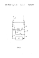
- FIG. 4 is a schematic representation of yet another embodiment of an internal combustion engine in accordance with the present invention with an exhaust gas feedback, guide vane control of an exhaust gas turbocharger, and an additional auxiliary blower for the combustion chamber.
- an internal combustion piston engine 11 is connected by way of a charging air line 12 with a compressor 13 and by an exhaust gas line 14 to an exhaust gas turbine 15.
- a bypass line 16 is disposed between the charging air line 12 and the exhaust gas line 14.
- a portion of the exhaust gas line 14 between the piston engine 11 and the exhaust gas turbine 15 includes a combustion chamber 17.
- a portion of the exhaust gas line 14 between the exhaust gas turbine 15 and an end of the exhaust gas line 14 is provided with a restricting and/or blocking means such as, for example, a single valve 18.
- a return line 20 branches off from a portion of the exhaust gas line 14 between the exhaust gas turbine 15 and the valve 18 with the return line 20 terminating in the charging air line 12.
- a restricting and/or blockgin valve 21 is provided for restricting and/or cutting off the flow of exhaust gases through the return line 20.
- the combustion chamber 17 is disposed in the exhaust gas line 14 upstream of the exhaust gas turbine 15 and the valve 18 is disposed at the end of the exhaust gas line 14 downstream of the exhaust gas turbine 15.
- the return line 20 may branch off the exhaust gas line 14 at a position between the exhaust gas turbine 15 and the combustion chamber 17 upstream of the exhaust gas turbine 15.
- a restriction and/or blocking means such as a valve 18' upstream of the exhaust gas turbine 15.
- the combustion chamber 17 is disposed in the bypass line 16 extending between the chargin air line 12 and the exhaust gas line 14 with the return line 20 branching off from the bypass line 16 at a point between the combustion chamber 17 and the exhaust gas line 14.
- the valve 18 is disposed in the bypass line 16 between the branching place of the return line 20 and the exhaust gas line 14. It is also possible to branch off the return line 20 from the exhaust gas line 14 and to dispose the valve 18 in the exhaust gas line 14 in the manner illustrated in FIG. 1.
- a restricting and/or blocking means such as a valve 24 is disposed in the exhaust gas line 14 upstream of the gas turbine 15 whereby exhaust gases from the internal combustion engine 11 and from the combustion chamber 17 disposed in the return line 16 can be recycled back to an exhaust gas return through a connecting line 25 which is controlled by a valve 26 for restricting and/or blocking the connecting line 25.
- a charging air cooler 31 is disposed in the charging air line 12 and is bypassed by a bypass line 16 and return line 20 as the charging air is heated up.
- An additional restricting and/or blocking means such as a valve 32 is disposed between the combustion chamber 17 and the branching off point of the return line 20 for the bypass line 16.
- a restricting and/or blocking means such as, for example, a valve 22 is located upstream of the combustion chamber 17 for controlling the throughflow through the combustion chamber 17 and an additional restricting and/or blocking valve 23 is disposed in the charging air line upstream of the charging air cooler 31.
- the exhaust gas from the combustion chamber 17 may be directed into the chargin air line or intake line of the internal combustion engine 11.
- the valves 18, 22, 26, 32 in an opened position and the valve 24 in a closed position, the exhaust gas from the combustion chamber 17 can be routed through the exhaust line 14 and connecting line 25 into the charging air line 12.
- the valve 23 is completely closed and the valve 22 is completely opened.
- the exhaust gas turbine 15 could be provided with adjustable guide vanes 27 (FIG. 4) to achieve the same blocking and/or restricting functions.
- another connecting line 29 is provided in which is arranged a restricting and/or blocking means such as, for example, a valve 28.
- a further restricting and/or blocking means for example, a valve 30, is provided in the exhaust gas line to slow down and/or control the flow of the exhaust gases in the exhaust gas line 14.
- a bypass line 33 provided with a restricting and/or blocking means such as a valve 34, is provided for bypassing the charging air cooler 31. With the valve 23 in a closed position and the valve 34 in a opened position, the bypass line 33 is cut in advantageously when the exhaust gases from the combustion chamber are used to drive the exhaust gas turbine and the compressed charging air is to be supplied to the piston engine without significant cooling.
- An auxiliary blower 37 driven by an electric motor 36, is provided at the combustion chamber 17 and serves to improve the combustion process in the combustion chamber 17 and to reduce the quantity of pollutants in the exhaust gases.
- the auxiliary blower 37 supplies the combustion chamber 17 with additional air only when required in order to achieve a smooth combustion.
- valve 18 and valve 21 are integrated into a valve arrangement 19 which functions to control the exhaust gas flow in the same manner as the valves 18, 21. In this manner, ever when the combustion chamber 17 is switched off, the exhaust gases can be recycled through the return line 20.
- the valves 22, 23 are provided in the bypass line 16 and charging air line 12 for respectively controlling the flow through the combustion chamber 17 and the charging air cooler 31. As with the embodiment of FIG. 3, the charging air cooler 31 in the charging air line 12 is bypassed by the bypass line 16 and return line 20 when the charging air is being heated up.
- the piston engine 11 creates a suction by way of the compressor 13, chargin air line 12, bypass line 16, through combustion chamber 17, by way of valves 18, 21 and/or valve arrangement 19, return line 20 and again through a section of the charging air line 12.
- the valve 18 and/or valve arrangement 19 is closed.
- FIGS. 1 and 2 by providing an appropriate diameter ratio between the charging air line 12 on the one hand and the bypass line 16 and return line 20 on the other hand, indicated schematically by a restriction 35 in the charging air line 12, most of the aspirated air is passed through the combustion chamber 17.
- the exhaust gases from the combustion chamber 17 can be used to drive the exhaust gas turbine 15 in the idle and partial load modes by closing valve 21 and opening valve 18 and/or by actuating valve arrangement 19.
- the continuously adjustable restricting and/or blocking means allows this transition to be accomplished continuously as a function of, for example, the charging air pressure, aspirated air temperature and/or cooling water temperature, and speed of the internal combustion engine 11 and/or exhaust gas turbine 15. These meansures allow recharging pressure to be increased and the rotational speed of the internal combustion engine 11 to be increased in a much shorter period of time.
- the combustion chamber 17 can be cut out.
- Restricting and/or blocking valves 18, 21, and/or valve arrangement 19, and restricting and/or blocking valves 22, 26, 28, and 34 are closed and restricting and/or blocking valves 23, 24 and 30 are opened. Operation of the piston engine 11 then proceeds in a conventional manner.
- valves can be controlled by conventional electronic means which adjust the respective valves in response to operating parameters and/or operating conditions of the internal combustion engine 11.
- the valves may, for example, be flat-type valves driven electrically as a function of the operating parameters and suitable conventional means may be provided for controlling the ignition and/or fuel metering for the internal combustion engine 11.
- the engine Aspirates air through the bypass line 16, return line 20, and through combustion chamber 17 with the combustion chamber being started by adding fuel and igniting the same, thereby heating the aspirated air from the engine 11.
- the engine 11 is then started by injecting fuel into the combustion spaces thereof. Additional air and/or exhaust gases from the exhaust gas line 14 may be added to the aspirated air.
- the exhaust gases are supplied to the combustion chamber 17 in dependence upon the requirements of the internal combustion engine 11 and the exhaust gas turbine 15 and as a function of the operating parameters and/or operational state of the engine 11, the preheating of the charging air, and the required amount of exhaust gases from the internal combustion engine 11 necessary to support the drive of the exhaust gas turbine 15.
- the total volume of the exhaust gases from the combustion chamber 17 together with the exhaust gases from the internal combustion engine 11 are fed to the exhaust gas turbine 15.
- the engine has a low compression ratio, all of the exhaust gases from the combustion chamber 17 are added to the charging air by way of the return line 20 to preheat the charging air. Additionally, the exhaust gases from th combustion chamber 17 together with the exhaust gases from the internal combustion engine 11 may be fed to the exhaust gas turbine 15 with the charging air being supplied to the internal combustion engine 11 by bypassing the charging air cooler 31.
Abstract
An internal combustion engine and a method of operating the same, which engine includes a supercharger having an exhaust gas turbine and a charging air compressor with a charging air line supplying charging air to the internal combustion engine. A bypass line is provided for connecting the charging air line with the exhaust gas line and a combustion chamber is disposed in one of the exhaust gas line and the bypass line. A return line for recycling exhaust gases branches off from the line in which the combustion chamber is disposed and a connecting line is provided for connecting the exhaust gas line with the charging air line. Arrangements are provided for at least one of selectively restricting and blocking at least one of the charging air line, bypass line, exhaust gas line and return line.
Description
The present invention relates to a piston engine and, more particularly, to a supercharged internal combustion piston engine which includes an exhaust gas turbine, a supercharging compressor, a bypass line connecting a charging or booster air line with an exhaust gas line, and a combustion chamber disposed in a line between the charging or booster air line and the exhaust gas turbine.
Arrangements have been proposed for cutting in and out the combustion chamber to support the exhaust gas turbocharger in those operating states in which the internal combustion engine itself does not produce sufficient exhaust gases. In such proposed arrangements, expensive additional assemblies are required to actuate the combustion chambers such as, for example, electrically driven auxiliary blowers, compressed air reservoirs whith shutoff, switching, and recharging devices, and/or auxiliary drives for the exhaust gas turbocharger with connecting and disconnecting devices to produce the required air throughput or throughflow through the combustion chamber for ignition.
Under extreme starting conditions with, for example, low air temperatures and/or low compression ratios in the internal combustion engine, it is necessary to, for example, employ a precompression of the charging or booster air and a preheating of such air in order to ensure a reliable starting. While heating devices for heating aspirated air in the charging or booster air line have been proposed for facilitating and/or permitting starting of an internal combustion engine, installation of the heating devices and/or combustion chambers in duplicate together with the necessary control devices results in a considerable construction cost.
The aim underlying the present invention assentially resides in providing an internal combustion engine arrangement which includes a combustion chamber for achieving an intensive preheating of the charging air for the internal combustion engine in addition to starting and supporting an exhaust gas turbocharger.
According to one advantageous feature of the present invention, a restricting and/or blocking means is arranged in an exhaust gas line extending between a combustion chamber and an end of the exhaust gas line with an exhaust gas return line, capable of being restricted and/or shut off, branching off from the exhaust gas line at a position between the combustion chamber and the restricting and/or blocking means with the return line terminating in the charging air line.
In a piston-type internal combustion engine in which a combustion chamber is disposed in a bypass line, according to another advantageous feature of the present invention, the exhaust gas return line branches off from the bypass line at a position between the combustion chamber and the exhaust line with a valve means being provided for simultaneously or alternately restricting and/or shutting off the return line and the passageway of the bypass line between the point at which the return line branches off and the exhaust gas line.
In accordance with further features of the present invention, the air is aspirated into the piston engine through the bypass line, return line, and through the combustion chamber when the engine is being started with the combustion chamber being started by adding fuel and igniting the same to heat the aspirated air from the piston engine with the piston engine then being started by injecting fuel into the combustion spaces thereof.
By virtue of these last-mentioned features, a vacuum effect of the engine can be used to start the combustion chamber without problems or any special starting devices when starting up the internal combustion engine and it is also possible to simultaneously achieve efficient heating of the charging air for the engine.
According to the present invention, aspirated air from the internal combustion engine may have additional air or exhaust gas added thereto from the exhaust gas line by virtue of the provision of restricting and/or blocking means in the exhaust gas line upstream of the exhaust gas turbocharger with the restricting and/or blocking means being in the form of control valves and/or adjustable vanes in the exhaust gas turbocharger. By virtue of these measures, the air heated by the compressive efforts of the internal combustion engine or the exhaust gas coming from the exhaust line is mixed with the exhaust gases from the combustion chamber and fed to the charging air.
When using an exhaust gas turbine which can be regulated by means of adjustable vanes which can be used advantageously as a restricting or blocking means in the exhaust gas line, the overall construction of the engine of the present invention can be considerably simplified.
In accordance with yet another feature of the present invention, immediately after starting or even during a starting phase, the exhaust gases from the combustion chamber are available for accelerating the exhaust gas turbocharger and/or for operating the exhaust gas turbocharger with the piston engine under a partial load operation.
According to the present invention, the exhaust gases are supplied to the combustion chamber in dependence upon the requirements of the engine and exhaust gas turbocharger and as a function of operating parameters and the operating state of the engine as well as the charging air for preheating and exhaust gases from the piston engine to support the drive of the exhaust gas turbocharger whereby operating with preheating of the charging air and simulataneous support of the exhaust gas turbine is possible during starting and under partial load operation of the engine so that a transition can be made from preference for preheating chargin air to increasing support for the exhaust gas turbine depending on thhe requirements.
According to yet another advantageous feature of the present invention, additional restricting and/or shutoff means are provided in the chargin air line downstream of the point at which the bypass line branches off and in the bypass line upstream of the combustion chamber with yet another restriction and/or blocking means being arranged in the bypass line leading from the combustion chamber to the branch-off position. The restriction and/or blocking means are continuously variable and control the throughflow by varying the cross-section of the respective lines thereby providing for a continuous adjustment of the individual gas streams in response to the changing operating parameters and operating states of the internal combustion engine.
For optimum conditions, with varying operating states, in accordance with the present invention, restricting and/or blocking means which can be fixed or set permanently can be disposed in a valve arrangement to determine the volume as well as the volume ratio of the individual gas streams.
The restricting and/or blocking means according to the present invention may advantageously be constructed as either individual valves and/or flat valves or as a single multipath valve. With individual flat-type valves,, there is provided a greater variety of possible means of regulation and variation; whereas, the single multipath valve offers the advantages of low cost and limited space requirements.
To provide additional support for heating the charging air, the exhaust gases from the combustion chamber and the internal combustion engine can be recycled to the charging air line according to the present invention by providing a connecting line which includes a blocking and/or restricting means with the connecting line extending from a point upstream of the exhaust gas turbocharger to the chargin air line.
Th recycling of thhe exhaust gases can also be accomplished in accordance with the present invention by providing a connecting line extending from th exhaust gas line to the charging air line with the connecting line including a restricting and/or blocking means and with a further restricting and/or blocking means being disposed in the exhaust gas line downstream of a point at which the connecting line branches from the exhaust gas line.
A charging air cooler may be operatively connected to or disposed within the charging air line according to the present invention in order to achieve a high charging air input to the cylinders of the internal combustion engine under a full load operation.
Advantageously, according to the present invention, the charging air is heated during the starting process and under a partial load operation of the internal combustion engine. For this purpose, the bypass line branches off from the charging air line upstream of a charging air cooler with thhe return line terminating in the charging air line downstream of the charging air cooler. Restriction and/or blocking means are provided in the bypass line for conrolling the throughflow of the air to the charging air cooler.
An electrically driven auxiliary blower may be provided for supplying auxiliary air to the combustion chamber to enhance the operation thereof. In contrast to the conventional auxiliary blowers required to start the combustion chamber, the auxiliary blower in accordance with the present invention can be constructed with relatively small dimensions since the blower supplies the combustion chamber with additional air only when required in order to achieve a smooth combustion.
The internal combustion engine according to the present invention allows for an advantageous use of a process for a zero-load and partial-load operation to achieve good acceleration capability by feeding the total volume of exhaust gases from the combustion chamber together with the exhaust gases from the internal combustion engine to the exhaust gas turbocharger thereby producing a high charging air pressure.
With low compression in the internal conbustion engine, at zero-load and partial-load operation, to ensure sufficient ignition conditions, according to the present invention, all of the exhaust gases from the combustion chamber are added to the charging air by way of a return line in order to preheat the charging air.
To facilitate the supply and control of the supply of the exhaust gases from the combustion chamber and the internal combustion engine to the charging air, a valve arragnement is provided for adding the exhaust gases together and directing the exhaust gases to the charging air line.
According to the present invention, with a low compression ratio, in order to ensure sufficient ignition conditions in the internal combustion engine, all of the exhaust gases from the piston engine are fed to the exhaust gas turbine to produce a high charging pressure and the charging air is supplies to the internal combustion engine by bypassing a charging air cooler.
Accordingly, it is an object of the present invention to provide an internal combustion engine and method of operating the same which avoids by simple means the disadvantages and drawbacks encountered in the prior art.
Another object of the present invention resides in providing an internal combustion engine and method of operating the same which facilitates and/or improves and, under extreme conditions, makes possible the starting and operation of the engine equipped with an exhaust gas turbocharger.
A further object of the present invention resides in providing an internal combustion engine and method of operating the same which utilizes a combustion chamber to achieve an intensive preheating of the charging air while nevertheless reducing the overall construction costs of the engine.
Yet another object of the present invention resides in providing an internal combustion engine and method of operating the same which eliminates the previously required additional starting assemblies for starting the combustion chamber.
A still further object of the present invention resides in providing an internal combustion engine and method of operating the same which functions reliably under all operating conditions.
These and other objects, features, and advantages of the present invention will become more apparent from the following description when taken in connection with the accompanying drawings which show, for the purposes of illustration only, several embodiments of an internal combustion engine in accordance with the present invention, and wherein:
FIG. 1 is a schematic representation of a first embodiment of a supercharged internal combustion engine with a combustion chamber arranged in an exhaust gas line;
FIG. 2 is a schematic representation of another embodiment of the internal combustion engine in accordance with the present invention with a combustion chamber disposed in a bypass line;
FIG. 3 is a schematic representation of a further embodiment of an internal combustion engine in accordance with the present invention with a charging air cooler and an additional exhaust gas feedback; and
FIG. 4 is a schematic representation of yet another embodiment of an internal combustion engine in accordance with the present invention with an exhaust gas feedback, guide vane control of an exhaust gas turbocharger, and an additional auxiliary blower for the combustion chamber.
Referring now to the drawings wherein like reference numerals are used throughout the various views to designate like parts and, more particularly, to FIG. 1, according to this figure, an internal combustion piston engine 11 is connected by way of a charging air line 12 with a compressor 13 and by an exhaust gas line 14 to an exhaust gas turbine 15. A bypass line 16 is disposed between the charging air line 12 and the exhaust gas line 14. A portion of the exhaust gas line 14 between the piston engine 11 and the exhaust gas turbine 15 includes a combustion chamber 17. A portion of the exhaust gas line 14 between the exhaust gas turbine 15 and an end of the exhaust gas line 14 is provided with a restricting and/or blocking means such as, for example, a single valve 18. A return line 20 branches off from a portion of the exhaust gas line 14 between the exhaust gas turbine 15 and the valve 18 with the return line 20 terminating in the charging air line 12. A restricting and/or blockgin valve 21 is provided for restricting and/or cutting off the flow of exhaust gases through the return line 20.
In the embodiment of FIG. 1, the combustion chamber 17 is disposed in the exhaust gas line 14 upstream of the exhaust gas turbine 15 and the valve 18 is disposed at the end of the exhaust gas line 14 downstream of the exhaust gas turbine 15. As shown in dotted line, the return line 20 may branch off the exhaust gas line 14 at a position between the exhaust gas turbine 15 and the combustion chamber 17 upstream of the exhaust gas turbine 15. However, as shown in dotted lines, in lieu of the valve 18, it is possible to dispose a restriction and/or blocking means such as a valve 18' upstream of the exhaust gas turbine 15.
As shown in FIG. 2, the combustion chamber 17 is disposed in the bypass line 16 extending between the chargin air line 12 and the exhaust gas line 14 with the return line 20 branching off from the bypass line 16 at a point between the combustion chamber 17 and the exhaust gas line 14. The valve 18 is disposed in the bypass line 16 between the branching place of the return line 20 and the exhaust gas line 14. It is also possible to branch off the return line 20 from the exhaust gas line 14 and to dispose the valve 18 in the exhaust gas line 14 in the manner illustrated in FIG. 1.
As shown in FIG. 3, a restricting and/or blocking means such as a valve 24 is disposed in the exhaust gas line 14 upstream of the gas turbine 15 whereby exhaust gases from the internal combustion engine 11 and from the combustion chamber 17 disposed in the return line 16 can be recycled back to an exhaust gas return through a connecting line 25 which is controlled by a valve 26 for restricting and/or blocking the connecting line 25. By virtue of this arrangement, it is possible to preheat the aspirated air especially during an idle operation and with the internal combustion engine 11 operating at a low load level. Before the piston engine 11 is started, the aspirated, compressed, and thereby additionally heated charging air can be mixed with the exhaust gases from the combustion chamber through the valve 18 and reaspirated. After the necessary air temperature is reached in the internal combustion engine 11, fuel is then injected into the combustion spaces of the engine in a conventional manner.
A charging air cooler 31 is disposed in the charging air line 12 and is bypassed by a bypass line 16 and return line 20 as the charging air is heated up. An additional restricting and/or blocking means such as a valve 32 is disposed between the combustion chamber 17 and the branching off point of the return line 20 for the bypass line 16.
A restricting and/or blocking means such as, for example, a valve 22 is located upstream of the combustion chamber 17 for controlling the throughflow through the combustion chamber 17 and an additional restricting and/or blocking valve 23 is disposed in the charging air line upstream of the charging air cooler 31.
By closing the control valve 18, the exhaust gas from the combustion chamber 17 may be directed into the chargin air line or intake line of the internal combustion engine 11. With the valves 18, 22, 26, 32, in an opened position and the valve 24 in a closed position, the exhaust gas from the combustion chamber 17 can be routed through the exhaust line 14 and connecting line 25 into the charging air line 12. When starting the piston engine 11, the valve 23 is completely closed and the valve 22 is completely opened. In lieu of the valve 24, the exhaust gas turbine 15 could be provided with adjustable guide vanes 27 (FIG. 4) to achieve the same blocking and/or restricting functions.
As shown in FIG. 4, another connecting line 29 is provided in which is arranged a restricting and/or blocking means such as, for example, a valve 28. A further restricting and/or blocking means, for example, a valve 30, is provided in the exhaust gas line to slow down and/or control the flow of the exhaust gases in the exhaust gas line 14. A bypass line 33, provided with a restricting and/or blocking means such as a valve 34, is provided for bypassing the charging air cooler 31. With the valve 23 in a closed position and the valve 34 in a opened position, the bypass line 33 is cut in advantageously when the exhaust gases from the combustion chamber are used to drive the exhaust gas turbine and the compressed charging air is to be supplied to the piston engine without significant cooling.
An auxiliary blower 37, driven by an electric motor 36, is provided at the combustion chamber 17 and serves to improve the combustion process in the combustion chamber 17 and to reduce the quantity of pollutants in the exhaust gases. The auxiliary blower 37 supplies the combustion chamber 17 with additional air only when required in order to achieve a smooth combustion.
In the FIG. 4 embodiment, the single valve 18 and valve 21 are integrated into a valve arrangement 19 which functions to control the exhaust gas flow in the same manner as the valves 18, 21. In this manner, ever when the combustion chamber 17 is switched off, the exhaust gases can be recycled through the return line 20. The valves 22, 23 are provided in the bypass line 16 and charging air line 12 for respectively controlling the flow through the combustion chamber 17 and the charging air cooler 31. As with the embodiment of FIG. 3, the charging air cooler 31 in the charging air line 12 is bypassed by the bypass line 16 and return line 20 when the charging air is being heated up.
During a starting operation, the piston engine 11 creates a suction by way of the compressor 13, chargin air line 12, bypass line 16, through combustion chamber 17, by way of valves 18, 21 and/or valve arrangement 19, return line 20 and again through a section of the charging air line 12. At this time, the valve 18 and/or valve arrangement 19 is closed. In the embodiments of FIGS. 1 and 2, by providing an appropriate diameter ratio between the charging air line 12 on the one hand and the bypass line 16 and return line 20 on the other hand, indicated schematically by a restriction 35 in the charging air line 12, most of the aspirated air is passed through the combustion chamber 17.
When fuel is injected into the combustion chamber 17 and ignited in a known manner, the ignition chamber 17 is started and the aspirated air intensively preheated. In this fashion, unfavorable ignition conditions such as, for example, a low compression ratio in the internal combustion engine 11 and/or low outside air temperatures can be compensated so that the injection of fuel into the internal combustion engine 11 then permits the same to readily start.
As the piston engine 11 heats up further, the exhaust gases from the combustion chamber 17 can be used to drive the exhaust gas turbine 15 in the idle and partial load modes by closing valve 21 and opening valve 18 and/or by actuating valve arrangement 19. The continuously adjustable restricting and/or blocking means allows this transition to be accomplished continuously as a function of, for example, the charging air pressure, aspirated air temperature and/or cooling water temperature, and speed of the internal combustion engine 11 and/or exhaust gas turbine 15. These meansures allow recharging pressure to be increased and the rotational speed of the internal combustion engine 11 to be increased in a much shorter period of time.
When the exhaust gas turbine 15 has reached its maximum speed with the internal combustion engine 11 at a peak load, and the charging air has reached its prescribed level, the combustion chamber 17 can be cut out. Restricting and/or blocking valves 18, 21, and/or valve arrangement 19, and restricting and/or blocking valves 22, 26, 28, and 34 are closed and restricting and/or blocking valves 23, 24 and 30 are opened. Operation of the piston engine 11 then proceeds in a conventional manner.
the restricting and/or blocking valves hereinabove can be controlled by conventional electronic means which adjust the respective valves in response to operating parameters and/or operating conditions of the internal combustion engine 11. The valves may, for example, be flat-type valves driven electrically as a function of the operating parameters and suitable conventional means may be provided for controlling the ignition and/or fuel metering for the internal combustion engine 11.
To start the engine 11, the engine aspirates air through the bypass line 16, return line 20, and through combustion chamber 17 with the combustion chamber being started by adding fuel and igniting the same, thereby heating the aspirated air from the engine 11. The engine 11 is then started by injecting fuel into the combustion spaces thereof. Additional air and/or exhaust gases from the exhaust gas line 14 may be added to the aspirated air. In operating the engine 11, the exhaust gases are supplied to the combustion chamber 17 in dependence upon the requirements of the internal combustion engine 11 and the exhaust gas turbine 15 and as a function of the operating parameters and/or operational state of the engine 11, the preheating of the charging air, and the required amount of exhaust gases from the internal combustion engine 11 necessary to support the drive of the exhaust gas turbine 15.
For zero-load and partial-load operation of the engine 11, in order to achieve good acceleration, the total volume of the exhaust gases from the combustion chamber 17 together with the exhaust gases from the internal combustion engine 11 are fed to the exhaust gas turbine 15.
If the engine has a low compression ratio, all of the exhaust gases from the combustion chamber 17 are added to the charging air by way of the return line 20 to preheat the charging air. Additionally, the exhaust gases from th combustion chamber 17 together with the exhaust gases from the internal combustion engine 11 may be fed to the exhaust gas turbine 15 with the charging air being supplied to the internal combustion engine 11 by bypassing the charging air cooler 31.
While we have shown and described several embodiments in accordance with the present invention, it is understood that the same is not limited thereto but is susceptible of numerous changes and modifications as known to a person skilled in the art, and we therefore do not wish to be limited to the details shown and described herein but intend to cover all such changes and modifications as encompassed by the scope of the appended claims.
Claims (6)
1. An internal combustion engine comprising a supercharging means including an exhaust gas turbine means and a charging air compressor means, a charging air line for supplying charging air from the charging air compressor means to the internal combustion engine, a bypass line means for connecting the charging air line with an exhaust gas line, a combustion chamber means disposed in the bypass line means, a return line branching off from said bypass line means at a point located between the combustion chamber means and a connecting place of the bypass line means with the exhaust gas line, said return line terminating in the charging air line, multipath valve means being provided in the bypass line means at the branching off point of the return line for controlling the flow through a portion of the bypass line means and through said return line, wherein the exhaust gas turbine means includes selectively adjustable guide vane means for controlling the flow through the exhaust gas line, and wherein a connecting line means is arranged between the charging air line and the exhaust gas line for recycling exhaust gasses between the exhaust gas line and the charging air line, said connecting line means being connected to the exhaust gas line at a place downstream of the exhaust gas turbine means so as to supply an output of the exhaust gas turbine means to the charging air line, and in that further valve means for controlling the flow through the exhaust gas line is arranged in the exhaust gas line at a place disposed downstream of the connecting place of the connecting line means with the exhaust gas line.
2. An engine according to claim 1, characterized in that a charging air cooler means is arranged in the charging air line, and in that the bypass line means is connected with the charging air line upstream of the charging air cooler means and the return line is connected with the charging air line downstream of the charging air cooler means.
3. An engine according to claim 2, characterized in that the bypass line means is additionally connected with said connecting line means, and in that valve means are arranged in the connecting line means for controlling the flow through said connecting line means, said last-mentioned valve means being arranged in the connecting line means at a position between the connecting place of the exhaust gas line with the connecting line means and a connecting place of the bypass line means with the connecting line means.
4. An engine according to claim 3, characterized in that a further valve means for controlling flow through the connecting line means is arraned between the connecting places of the bypass line means and the charging air line with said connecting line means.
5. An engine according to claim 4, characterized in that means are provided for supplying additional combustion air to the combustion chamber means.
6. An engine according to claim 5, characterized in that said means for supplying additional combustion air includes an auxiliary blower operatively associated with said combustion chamber means.
Applications Claiming Priority (2)
| Application Number | Priority Date | Filing Date | Title |
|---|---|---|---|
| DE2706696 | 1977-02-17 | ||
| DE2706696A DE2706696C2 (en) | 1977-02-17 | 1977-02-17 | Method for starting the combustion chamber of an internal combustion engine |
Publications (1)
| Publication Number | Publication Date |
|---|---|
| US4215550A true US4215550A (en) | 1980-08-05 |
Family
ID=6001417
Family Applications (1)
| Application Number | Title | Priority Date | Filing Date |
|---|---|---|---|
| US05/877,031 Expired - Lifetime US4215550A (en) | 1977-02-17 | 1978-02-10 | Supercharged internal combustion engine and method of operation thereof |
Country Status (8)
| Country | Link |
|---|---|
| US (1) | US4215550A (en) |
| JP (1) | JPS6017930B2 (en) |
| CH (1) | CH631240A5 (en) |
| DE (1) | DE2706696C2 (en) |
| ES (1) | ES467001A1 (en) |
| FR (1) | FR2381175A1 (en) |
| GB (1) | GB1565325A (en) |
| IT (1) | IT1090560B (en) |
Cited By (56)
| Publication number | Priority date | Publication date | Assignee | Title |
|---|---|---|---|---|
| US4355503A (en) * | 1979-01-12 | 1982-10-26 | Daimler-Benz Aktiengesellschaft | Exhaust gas turbocharger |
| US4404805A (en) * | 1980-03-21 | 1983-09-20 | Societe D'etudes De Machines Thermiques S.E.M.T. | Method of and system for power generation by supercharged internal combustion engine |
| US4622816A (en) * | 1983-02-03 | 1986-11-18 | Office National D'etudes Et De Recherches Aerospatiales (Par Abreviation O.N.E.R.A.) | Internal combustion engine supercharged by turbocompressor |
| US4833886A (en) * | 1982-11-02 | 1989-05-30 | Bbc Brown, Boveri & Company, Ltd. | Internal combustion engine supercharged by means of an exhaust gas turbocharger |
| US5163295A (en) * | 1991-09-09 | 1992-11-17 | Eaton Corporation | Controlling exhaust gas recirculation in a pressure boosted internal combustion engine |
| US5724813A (en) * | 1996-01-26 | 1998-03-10 | Caterpillar Inc. | Compressor by-pass and valving for a turbocharger |
| US5771868A (en) * | 1997-07-03 | 1998-06-30 | Turbodyne Systems, Inc. | Turbocharging systems for internal combustion engines |
| US5806308A (en) * | 1997-07-07 | 1998-09-15 | Southwest Research Institute | Exhaust gas recirculation system for simultaneously reducing NOx and particulate matter |
| AT2540U1 (en) * | 1997-12-16 | 1998-12-28 | Avl List Gmbh | INTERNAL COMBUSTION ENGINE WITH AT LEAST ONE COMPRESSOR FOR PRE-COMPRESSING THE INTAKE AIR |
| US5927075A (en) * | 1997-06-06 | 1999-07-27 | Turbodyne Systems, Inc. | Method and apparatus for exhaust gas recirculation control and power augmentation in an internal combustion engine |
| EP0931917A2 (en) * | 1998-01-21 | 1999-07-28 | Toyota Jidosha Kabushiki Kaisha | Combustion heater for internal combustion engine |
| US5937651A (en) * | 1997-07-03 | 1999-08-17 | Daimler-Benz A.G. | Internal combustion engine with exhaust gas turbocharger |
| US6003316A (en) * | 1995-04-11 | 1999-12-21 | Nederlandse Organisatie Voor Toegepast-Natuurwetenschappelijk Onderzoek Tno | Exhaust-gas recirculation system for a turbocharged internal combustion engine |
| US6053144A (en) * | 1998-11-05 | 2000-04-25 | Caterpillar Inc. | Diesel engine with a combustor which provides combustion products to reduce NOx production in a combustion chamber |
| US6076353A (en) * | 1999-01-26 | 2000-06-20 | Ford Global Technologies, Inc. | Coordinated control method for turbocharged diesel engines having exhaust gas recirculation |
| US6089019A (en) * | 1999-01-15 | 2000-07-18 | Borgwarner Inc. | Turbocharger and EGR system |
| US6205785B1 (en) | 1999-07-21 | 2001-03-27 | Caterpillar Inc. | Exhaust gas recirculation system |
| US6227178B1 (en) * | 1997-11-18 | 2001-05-08 | Toyota Jidosha Kabushiki Kaisha | Control system of combustion heater for internal combustion engine |
| US6230695B1 (en) * | 1999-03-22 | 2001-05-15 | Caterpillar Inc. | Exhaust gas recirculation system |
| US6276139B1 (en) | 2000-03-16 | 2001-08-21 | Ford Global Technologies, Inc. | Automotive engine with controlled exhaust temperature and oxygen concentration |
| EP1138928A2 (en) | 2000-03-27 | 2001-10-04 | Mack Trucks, Inc. | Turbocharged engine with exhaust gas recirculation |
| US6311494B2 (en) | 1999-08-20 | 2001-11-06 | Cummins Engine Company, Inc. | Exhaust gas recirculation system for a turbocharged internal combustion engine |
| US6321697B1 (en) * | 1999-06-07 | 2001-11-27 | Mitsubishi Heavy Industries, Ltd. | Cooling apparatus for vehicular engine |
| US6351946B1 (en) * | 1999-09-27 | 2002-03-05 | Caterpillar Inc. | Exhaust gas recirculation system in an internal combustion engine |
| US6360535B1 (en) | 2000-10-11 | 2002-03-26 | Ingersoll-Rand Company | System and method for recovering energy from an air compressor |
| US6378515B1 (en) | 2000-06-09 | 2002-04-30 | Mack Trucks, Inc. | Exhaust gas recirculation apparatus and method |
| US6526752B2 (en) | 2001-01-31 | 2003-03-04 | Cummins, Inc. | Passive engine exhaust flow restriction arrangement |
| CN1115472C (en) * | 1997-10-20 | 2003-07-23 | 丰田自动车株式会社 | Internal combustion engine having combustion heater |
| US20040050375A1 (en) * | 2002-08-21 | 2004-03-18 | Arnold Steven Don | Dual path EGR system and methods |
| US6755022B2 (en) | 2002-02-28 | 2004-06-29 | Mack Trucks, Inc. | Turbo-charged internal combustion engine with in-cylinder EGR and injection rate shaping |
| US6805093B2 (en) | 2002-04-30 | 2004-10-19 | Mack Trucks, Inc. | Method and apparatus for combining exhaust gas recirculation and engine exhaust braking using single valve actuation |
| US6820599B2 (en) | 2003-02-03 | 2004-11-23 | Ford Global Technologies, Llc | System and method for reducing Nox emissions during transient conditions in a diesel fueled vehicle with EGR |
| US20050045407A1 (en) * | 2003-08-28 | 2005-03-03 | Bulicz Tytus R. | Clean, low-pressure EGR in a turbocharged engine by back-pressure control |
| US6863058B2 (en) | 2003-02-03 | 2005-03-08 | Ford Global Technologies, Llc | System and method for reducing NOx emissions during transient conditions in a diesel fueled vehicle |
| US20050103013A1 (en) * | 2003-11-17 | 2005-05-19 | Dennis Brookshire | Dual and hybrid EGR systems for use with turbocharged engine |
| US7000393B1 (en) | 2005-04-14 | 2006-02-21 | International Engine Intellectual Property Company, Llc | System and method for relieving engine back-pressure by selectively bypassing a stage of a two-stage turbocharger during non-use of EGR |
| FR2891050A1 (en) * | 2005-09-20 | 2007-03-23 | Renault Sas | Air supercharging plant for Diesel type single cylinder test bench, has cooler and reheater provided in downstream connection with temperature control valves connected by channel and mounted in opposition for forming mixer |
| US20070068158A1 (en) * | 2005-09-28 | 2007-03-29 | Harold Sun | System and method for reducing surge |
| EP1977095A1 (en) * | 2006-01-13 | 2008-10-08 | Mack Trucks, Inc. | Controlling temperature of exhaust and intake gas |
| US20090120089A1 (en) * | 2007-11-14 | 2009-05-14 | General Electric Company | Purge system for an exhaust gas recirculation system |
| US20090151353A1 (en) * | 2007-12-14 | 2009-06-18 | General Electric Company | Control system for an egr purge system |
| US20090194079A1 (en) * | 2006-06-29 | 2009-08-06 | Toyota Jidosha Kabushiki Kaisha | Exhaust gas recirculation device of internal combustion engine, and control method thereof |
| US20100272588A1 (en) * | 2009-04-28 | 2010-10-28 | Alberto Scotti Del Greco | Energy recovery system in a gas compression plant |
| US20110146282A1 (en) * | 2009-12-18 | 2011-06-23 | General Electric Company | System and method for reducing sulfur compounds within fuel stream for turbomachine |
| US20110162360A1 (en) * | 2010-08-17 | 2011-07-07 | Ford Global Technologies, Llc | Egr mixer for high-boost engine systems |
| US20130232972A1 (en) * | 2010-10-27 | 2013-09-12 | Mtu Friedrichshafen Gmbh | Internal combustion engine |
| CN103827462A (en) * | 2011-07-12 | 2014-05-28 | Mtu腓特烈港有限责任公司 | Internal combustion machine, water craft, and method for operating the power supply system of a ship using an internal combustion machine |
| US20150007561A1 (en) * | 2013-07-05 | 2015-01-08 | Denso Thermal Systems S.P.A. | Active conditioning system of a gaseous fluid intake of an internal combustion engine |
| US20150192094A1 (en) * | 2014-01-03 | 2015-07-09 | Deere & Company | Power System Comprising an EGR System |
| US9273596B2 (en) | 2011-11-16 | 2016-03-01 | Toyota Motor Engineering & Manufacturing North America, Inc. | Boost extraction method of secondary air injection for internal combustion engine emission control |
| US20160245112A1 (en) * | 2015-02-24 | 2016-08-25 | General Electric Technology Gmbh | Method for operating a gas turbine arrangement |
| WO2018002037A1 (en) * | 2016-06-30 | 2018-01-04 | IFP Energies Nouvelles | Device and method for controlling the injection of air and exhaust gas at the intake of a supercharged internal combustion engine |
| CN114458440A (en) * | 2021-12-28 | 2022-05-10 | 中国北方发动机研究所(天津) | Cross afterburning exhaust gas turbocharging system |
| IL258770B (en) * | 2018-04-17 | 2022-12-01 | Zhmudyak Leonid | Method of controlling of turbocharging of aircraft engine |
| EP4187069A1 (en) * | 2021-11-24 | 2023-05-31 | Raytheon Technologies Corporation | Multi-mode engine system with gas turbine engine and turbo-compressor |
| US20230287817A1 (en) * | 2020-08-05 | 2023-09-14 | Mercedes-Benz Group AG | Internal Combustion Engine for a Motor Vehicle, and Motor Vehicle |
Families Citing this family (23)
| Publication number | Priority date | Publication date | Assignee | Title |
|---|---|---|---|---|
| GB1599761A (en) * | 1977-03-12 | 1981-10-07 | Lucas Industries Ltd | Turbo-supercharged compression ignition engine |
| DE3002701A1 (en) * | 1980-01-25 | 1981-07-30 | M.A.N. Maschinenfabrik Augsburg-Nürnberg AG, 8900 Augsburg | CHARGING SYSTEM FOR AN INTERNAL COMBUSTION ENGINE |
| FR2495689A1 (en) * | 1980-12-08 | 1982-06-11 | Hyperbar Develop Suralimentati | Coolant circuit for diesel engine - has heat exchanger in air intake for recuperator air and fuel circuit |
| DE3046876A1 (en) * | 1980-12-12 | 1982-07-15 | Mtu Motoren- Und Turbinen-Union Friedrichshafen Gmbh, 7990 Friedrichshafen | "INTERNAL COMBUSTION ENGINE" |
| JPS5918230A (en) * | 1982-07-21 | 1984-01-30 | Kanesaka Gijutsu Kenkyusho:Kk | Compression ignition engine provided with low compression ratio turbo-supercharger |
| DE4024572C2 (en) * | 1990-08-02 | 1994-11-10 | Kloeckner Humboldt Deutz Ag | Register charging for internal combustion engines in commercial vehicles |
| JP3658970B2 (en) | 1997-12-08 | 2005-06-15 | トヨタ自動車株式会社 | Internal combustion engine having a combustion heater |
| DE69816579T2 (en) | 1997-12-19 | 2004-06-03 | Toyota Jidosha K.K., Toyota | Internal combustion engine with NOx catalyst for lean mixture combustion |
| JP3528557B2 (en) * | 1997-12-22 | 2004-05-17 | トヨタ自動車株式会社 | Internal combustion engine having a combustion heater |
| JP3577961B2 (en) | 1998-02-27 | 2004-10-20 | トヨタ自動車株式会社 | Internal combustion engine having a combustion heater |
| JP3509563B2 (en) | 1998-03-10 | 2004-03-22 | トヨタ自動車株式会社 | Internal combustion engine having a combustion heater |
| JP3577946B2 (en) * | 1998-04-27 | 2004-10-20 | トヨタ自動車株式会社 | Compression ignition type internal combustion engine having a combustion type heater |
| JP3557928B2 (en) | 1998-12-22 | 2004-08-25 | トヨタ自動車株式会社 | Internal combustion engine having lean NOx catalyst |
| JP3454174B2 (en) | 1998-12-22 | 2003-10-06 | トヨタ自動車株式会社 | Exhaust gas purification system for hybrid vehicles |
| GB2393999B (en) * | 2002-10-04 | 2004-09-29 | Visteon Global Tech Inc | Reduction of turbo-lag in an internal combustion engine |
| FR2855562A1 (en) * | 2003-06-02 | 2004-12-03 | Valeo Climatisation | Heat transfer device for use in motor vehicles power unit, has set of primary units and set of secondary units, where secondary units are integrated or replaced by one of existing components of power unit of vehicle |
| DE102004029538A1 (en) * | 2004-06-18 | 2006-01-05 | Robert Bosch Gmbh | Charging device for internal combustion engines with pulse jet support |
| DE102006009319B4 (en) * | 2006-03-01 | 2017-03-30 | Volkswagen Ag | Method and device for operating an internal combustion engine |
| DE102011077147A1 (en) * | 2011-06-07 | 2012-12-13 | Abb Turbo Systems Ag | Exhaust duct system of internal combustion engine, has valves for switching on and off return lines provided from exhaust gas receiver to air receiver and from turbine to air receiver |
| FR3006006B1 (en) * | 2013-05-24 | 2015-12-04 | Peugeot Citroen Automobiles Sa | SEPARATE EXHAUST GAS RECIRCULATION DEVICE FOR INTERNAL COMBUSTION ENGINE. |
| FR3027955A1 (en) * | 2014-10-30 | 2016-05-06 | Peugeot Citroen Automobiles Sa | SUPERIOR THERMAL MOTOR WITH RECIRCULATION CIRCUIT FOR TURBINE DERIVATION |
| FR3036738B1 (en) * | 2015-05-28 | 2017-05-26 | Ifp Energies Now | DEVICE FOR CONTROLLING A QUANTITY OF AIR INTRODUCED TO THE ADMISSION OF A SUPERIOR INTERNAL COMBUSTION ENGINE AND EXHAUST COOLING - METHOD USING SUCH A DEVICE. |
| EP4257812A1 (en) * | 2022-04-05 | 2023-10-11 | Winterthur Gas & Diesel Ltd. | Internal combustion engine |
Citations (5)
| Publication number | Priority date | Publication date | Assignee | Title |
|---|---|---|---|---|
| US2216494A (en) * | 1937-10-21 | 1940-10-01 | Maschf Augsburg Nuernberg Ag | Internal combustion engine |
| US3423927A (en) * | 1965-10-28 | 1969-01-28 | Daimler Benz Ag | Installation for the operation of a diesel engine with exhaust gas turbo-charger |
| US3775971A (en) * | 1971-04-05 | 1973-12-04 | Saab Scania Ab | System for controlling the supply of air to an internal combustion engine |
| US3972644A (en) * | 1975-01-27 | 1976-08-03 | Caterpillar Tractor Co. | Vane control arrangement for variable area turbine nozzle |
| US4078387A (en) * | 1975-04-24 | 1978-03-14 | Etat Francais | Power units comprising a supercharged internal combustion engine |
Family Cites Families (6)
| Publication number | Priority date | Publication date | Assignee | Title |
|---|---|---|---|---|
| DE233349C (en) * | ||||
| US2633698A (en) * | 1948-02-05 | 1953-04-07 | Nettel Frederick | Turbosupercharger means to heat intake of compression-ignition engine for starting |
| DE1237835B (en) * | 1960-09-08 | 1967-03-30 | Daimler Benz Ag | Method and device for operating self-igniting, rechargeable internal combustion engines |
| DE1451888A1 (en) * | 1964-12-15 | 1970-05-14 | Daimler Benz Ag | Device to facilitate the starting of particularly charged diesel engines |
| US3925989A (en) * | 1974-04-15 | 1975-12-16 | Case Co J I | Turbocharger exhaust gas recirculation system |
| FR2271394B1 (en) * | 1974-05-15 | 1978-03-24 | France Etat |
-
1977
- 1977-02-17 DE DE2706696A patent/DE2706696C2/en not_active Expired
- 1977-12-12 IT IT52150/77A patent/IT1090560B/en active
-
1978
- 1978-02-10 US US05/877,031 patent/US4215550A/en not_active Expired - Lifetime
- 1978-02-15 ES ES467001A patent/ES467001A1/en not_active Expired
- 1978-02-16 GB GB6203/78A patent/GB1565325A/en not_active Expired
- 1978-02-16 CH CH172478A patent/CH631240A5/en not_active IP Right Cessation
- 1978-02-16 FR FR7804398A patent/FR2381175A1/en active Granted
-
1982
- 1982-01-21 JP JP57006871A patent/JPS6017930B2/en not_active Expired
Patent Citations (5)
| Publication number | Priority date | Publication date | Assignee | Title |
|---|---|---|---|---|
| US2216494A (en) * | 1937-10-21 | 1940-10-01 | Maschf Augsburg Nuernberg Ag | Internal combustion engine |
| US3423927A (en) * | 1965-10-28 | 1969-01-28 | Daimler Benz Ag | Installation for the operation of a diesel engine with exhaust gas turbo-charger |
| US3775971A (en) * | 1971-04-05 | 1973-12-04 | Saab Scania Ab | System for controlling the supply of air to an internal combustion engine |
| US3972644A (en) * | 1975-01-27 | 1976-08-03 | Caterpillar Tractor Co. | Vane control arrangement for variable area turbine nozzle |
| US4078387A (en) * | 1975-04-24 | 1978-03-14 | Etat Francais | Power units comprising a supercharged internal combustion engine |
Cited By (91)
| Publication number | Priority date | Publication date | Assignee | Title |
|---|---|---|---|---|
| US4355503A (en) * | 1979-01-12 | 1982-10-26 | Daimler-Benz Aktiengesellschaft | Exhaust gas turbocharger |
| US4404805A (en) * | 1980-03-21 | 1983-09-20 | Societe D'etudes De Machines Thermiques S.E.M.T. | Method of and system for power generation by supercharged internal combustion engine |
| US4833886A (en) * | 1982-11-02 | 1989-05-30 | Bbc Brown, Boveri & Company, Ltd. | Internal combustion engine supercharged by means of an exhaust gas turbocharger |
| US4622816A (en) * | 1983-02-03 | 1986-11-18 | Office National D'etudes Et De Recherches Aerospatiales (Par Abreviation O.N.E.R.A.) | Internal combustion engine supercharged by turbocompressor |
| US5163295A (en) * | 1991-09-09 | 1992-11-17 | Eaton Corporation | Controlling exhaust gas recirculation in a pressure boosted internal combustion engine |
| US6003316A (en) * | 1995-04-11 | 1999-12-21 | Nederlandse Organisatie Voor Toegepast-Natuurwetenschappelijk Onderzoek Tno | Exhaust-gas recirculation system for a turbocharged internal combustion engine |
| US5724813A (en) * | 1996-01-26 | 1998-03-10 | Caterpillar Inc. | Compressor by-pass and valving for a turbocharger |
| US5927075A (en) * | 1997-06-06 | 1999-07-27 | Turbodyne Systems, Inc. | Method and apparatus for exhaust gas recirculation control and power augmentation in an internal combustion engine |
| US5937651A (en) * | 1997-07-03 | 1999-08-17 | Daimler-Benz A.G. | Internal combustion engine with exhaust gas turbocharger |
| US5771868A (en) * | 1997-07-03 | 1998-06-30 | Turbodyne Systems, Inc. | Turbocharging systems for internal combustion engines |
| US5806308A (en) * | 1997-07-07 | 1998-09-15 | Southwest Research Institute | Exhaust gas recirculation system for simultaneously reducing NOx and particulate matter |
| CN1115472C (en) * | 1997-10-20 | 2003-07-23 | 丰田自动车株式会社 | Internal combustion engine having combustion heater |
| EP1186758A3 (en) * | 1997-10-20 | 2004-02-04 | Toyota Jidosha Kabushiki Kaisha | Internal combustion engine having combustion heater |
| US6227178B1 (en) * | 1997-11-18 | 2001-05-08 | Toyota Jidosha Kabushiki Kaisha | Control system of combustion heater for internal combustion engine |
| AT2540U1 (en) * | 1997-12-16 | 1998-12-28 | Avl List Gmbh | INTERNAL COMBUSTION ENGINE WITH AT LEAST ONE COMPRESSOR FOR PRE-COMPRESSING THE INTAKE AIR |
| EP0931917A2 (en) * | 1998-01-21 | 1999-07-28 | Toyota Jidosha Kabushiki Kaisha | Combustion heater for internal combustion engine |
| EP0931917B1 (en) * | 1998-01-21 | 2003-10-01 | Toyota Jidosha Kabushiki Kaisha | Combustion heater for internal combustion engine |
| US6053144A (en) * | 1998-11-05 | 2000-04-25 | Caterpillar Inc. | Diesel engine with a combustor which provides combustion products to reduce NOx production in a combustion chamber |
| EP1612390A2 (en) * | 1999-01-15 | 2006-01-04 | BorgWarner Inc. | Turbocharger and EGR system |
| US6089019A (en) * | 1999-01-15 | 2000-07-18 | Borgwarner Inc. | Turbocharger and EGR system |
| US6263672B1 (en) * | 1999-01-15 | 2001-07-24 | Borgwarner Inc. | Turbocharger and EGR system |
| EP1612390A3 (en) * | 1999-01-15 | 2006-01-18 | BorgWarner Inc. | Turbocharger and EGR system |
| US6076353A (en) * | 1999-01-26 | 2000-06-20 | Ford Global Technologies, Inc. | Coordinated control method for turbocharged diesel engines having exhaust gas recirculation |
| US6230695B1 (en) * | 1999-03-22 | 2001-05-15 | Caterpillar Inc. | Exhaust gas recirculation system |
| US6321697B1 (en) * | 1999-06-07 | 2001-11-27 | Mitsubishi Heavy Industries, Ltd. | Cooling apparatus for vehicular engine |
| US6205785B1 (en) | 1999-07-21 | 2001-03-27 | Caterpillar Inc. | Exhaust gas recirculation system |
| US6354084B1 (en) | 1999-08-20 | 2002-03-12 | Cummins Engine Company, Inc. | Exhaust gas recirculation system for a turbocharged internal combustion engine |
| US6311494B2 (en) | 1999-08-20 | 2001-11-06 | Cummins Engine Company, Inc. | Exhaust gas recirculation system for a turbocharged internal combustion engine |
| US6351946B1 (en) * | 1999-09-27 | 2002-03-05 | Caterpillar Inc. | Exhaust gas recirculation system in an internal combustion engine |
| US6276139B1 (en) | 2000-03-16 | 2001-08-21 | Ford Global Technologies, Inc. | Automotive engine with controlled exhaust temperature and oxygen concentration |
| EP1138928A3 (en) * | 2000-03-27 | 2002-08-07 | Mack Trucks, Inc. | Turbocharged engine with exhaust gas recirculation |
| US6470864B2 (en) | 2000-03-27 | 2002-10-29 | Mack Trucks, Inc. | Turbocharged engine with exhaust gas recirculation |
| EP1138928A2 (en) | 2000-03-27 | 2001-10-04 | Mack Trucks, Inc. | Turbocharged engine with exhaust gas recirculation |
| US6378515B1 (en) | 2000-06-09 | 2002-04-30 | Mack Trucks, Inc. | Exhaust gas recirculation apparatus and method |
| US6360535B1 (en) | 2000-10-11 | 2002-03-26 | Ingersoll-Rand Company | System and method for recovering energy from an air compressor |
| US6526752B2 (en) | 2001-01-31 | 2003-03-04 | Cummins, Inc. | Passive engine exhaust flow restriction arrangement |
| US20050139175A1 (en) * | 2002-02-28 | 2005-06-30 | Mack Trucks, Inc. | Turbo-charged internal combustion engine with in-cylinder egr and injection rate shaping |
| US6968831B2 (en) | 2002-02-28 | 2005-11-29 | Mack Trucks, Inc. | Turbo-charged internal combustion engine with in-cylinder EGR and injection rate shaping |
| US6755022B2 (en) | 2002-02-28 | 2004-06-29 | Mack Trucks, Inc. | Turbo-charged internal combustion engine with in-cylinder EGR and injection rate shaping |
| US6805093B2 (en) | 2002-04-30 | 2004-10-19 | Mack Trucks, Inc. | Method and apparatus for combining exhaust gas recirculation and engine exhaust braking using single valve actuation |
| US6899090B2 (en) * | 2002-08-21 | 2005-05-31 | Honeywell International, Inc. | Dual path EGR system and methods |
| US20040050375A1 (en) * | 2002-08-21 | 2004-03-18 | Arnold Steven Don | Dual path EGR system and methods |
| US20050045163A1 (en) * | 2003-02-03 | 2005-03-03 | Kurtz Eric Matthew | System and method for reducing NOx emissions during transient conditions in a diesel fueled vehicle with EGR |
| US6863058B2 (en) | 2003-02-03 | 2005-03-08 | Ford Global Technologies, Llc | System and method for reducing NOx emissions during transient conditions in a diesel fueled vehicle |
| US6820599B2 (en) | 2003-02-03 | 2004-11-23 | Ford Global Technologies, Llc | System and method for reducing Nox emissions during transient conditions in a diesel fueled vehicle with EGR |
| USRE42609E1 (en) | 2003-02-03 | 2011-08-16 | Ford Global Technologies, Llc | System and method for reducing NOx emissions during transient conditions in a diesel fueled vehicle with EGR |
| US7273045B2 (en) | 2003-02-03 | 2007-09-25 | Ford Global Technologies, Llc | System and method for reducing NOx emissions during transient conditions in a diesel fueled vehicle with EGR |
| US7131271B2 (en) | 2003-08-28 | 2006-11-07 | International Engine Intellectual Property Company, Llc | Clean, low-pressure EGR in a turbocharged engine by back-pressure control |
| US20050045407A1 (en) * | 2003-08-28 | 2005-03-03 | Bulicz Tytus R. | Clean, low-pressure EGR in a turbocharged engine by back-pressure control |
| US20060124115A1 (en) * | 2003-11-17 | 2006-06-15 | Dennis Brookshire | Dual and hybrid EGR systems for use with turbocharged engine |
| US7165540B2 (en) * | 2003-11-17 | 2007-01-23 | Honeywell International Inc. | Dual and hybrid EGR systems for use with turbocharged engine |
| US7013879B2 (en) | 2003-11-17 | 2006-03-21 | Honeywell International, Inc. | Dual and hybrid EGR systems for use with turbocharged engine |
| US20050103013A1 (en) * | 2003-11-17 | 2005-05-19 | Dennis Brookshire | Dual and hybrid EGR systems for use with turbocharged engine |
| US7000393B1 (en) | 2005-04-14 | 2006-02-21 | International Engine Intellectual Property Company, Llc | System and method for relieving engine back-pressure by selectively bypassing a stage of a two-stage turbocharger during non-use of EGR |
| FR2891050A1 (en) * | 2005-09-20 | 2007-03-23 | Renault Sas | Air supercharging plant for Diesel type single cylinder test bench, has cooler and reheater provided in downstream connection with temperature control valves connected by channel and mounted in opposition for forming mixer |
| US20070068158A1 (en) * | 2005-09-28 | 2007-03-29 | Harold Sun | System and method for reducing surge |
| US7322194B2 (en) * | 2005-09-28 | 2008-01-29 | Ford Global Technologies Llc | System and method for reducing surge |
| EP1977095A1 (en) * | 2006-01-13 | 2008-10-08 | Mack Trucks, Inc. | Controlling temperature of exhaust and intake gas |
| EP1977095A4 (en) * | 2006-01-13 | 2014-07-23 | Mack Trucks | Controlling temperature of exhaust and intake gas |
| US20090194079A1 (en) * | 2006-06-29 | 2009-08-06 | Toyota Jidosha Kabushiki Kaisha | Exhaust gas recirculation device of internal combustion engine, and control method thereof |
| US7717099B2 (en) * | 2006-06-29 | 2010-05-18 | Toyota Jidosha Kabushiki Kaisha | Exhaust gas recirculation device of internal combustion engine, and control method thereof |
| US20090120089A1 (en) * | 2007-11-14 | 2009-05-14 | General Electric Company | Purge system for an exhaust gas recirculation system |
| US7870718B2 (en) * | 2007-11-14 | 2011-01-18 | General Electric Company | Purge system for an exhaust gas recirculation system |
| US7866140B2 (en) * | 2007-12-14 | 2011-01-11 | General Electric Company | Control system for an EGR purge system |
| US20090151353A1 (en) * | 2007-12-14 | 2009-06-18 | General Electric Company | Control system for an egr purge system |
| US20100272588A1 (en) * | 2009-04-28 | 2010-10-28 | Alberto Scotti Del Greco | Energy recovery system in a gas compression plant |
| US8567184B2 (en) * | 2009-04-28 | 2013-10-29 | Nuovo Pignone S.P.A. | Energy recovery system in a gas compression plant |
| US20110146282A1 (en) * | 2009-12-18 | 2011-06-23 | General Electric Company | System and method for reducing sulfur compounds within fuel stream for turbomachine |
| US20110162360A1 (en) * | 2010-08-17 | 2011-07-07 | Ford Global Technologies, Llc | Egr mixer for high-boost engine systems |
| US8056340B2 (en) * | 2010-08-17 | 2011-11-15 | Ford Global Technologies, Llc | EGR mixer for high-boost engine systems |
| US9316180B2 (en) * | 2010-10-27 | 2016-04-19 | Mtu Friedrichshafen Gmbh | Internal combustion engine |
| US20130232972A1 (en) * | 2010-10-27 | 2013-09-12 | Mtu Friedrichshafen Gmbh | Internal combustion engine |
| DE102010043027B4 (en) * | 2010-10-27 | 2019-08-14 | Mtu Friedrichshafen Gmbh | Internal combustion engine |
| CN103827462A (en) * | 2011-07-12 | 2014-05-28 | Mtu腓特烈港有限责任公司 | Internal combustion machine, water craft, and method for operating the power supply system of a ship using an internal combustion machine |
| CN103827462B (en) * | 2011-07-12 | 2018-04-10 | Mtu 腓特烈港有限责任公司 | Internal combustion engine, ship and the method for utilizing internal combustion engine operation power supply network peculiar to vessel |
| US9273596B2 (en) | 2011-11-16 | 2016-03-01 | Toyota Motor Engineering & Manufacturing North America, Inc. | Boost extraction method of secondary air injection for internal combustion engine emission control |
| US20150007561A1 (en) * | 2013-07-05 | 2015-01-08 | Denso Thermal Systems S.P.A. | Active conditioning system of a gaseous fluid intake of an internal combustion engine |
| US9435252B2 (en) * | 2013-07-05 | 2016-09-06 | Denso Thermal Systems S.P.A. | Active conditioning system of a gaseous fluid intake of an internal combustion engine |
| US20150192094A1 (en) * | 2014-01-03 | 2015-07-09 | Deere & Company | Power System Comprising an EGR System |
| US9145852B2 (en) * | 2014-01-03 | 2015-09-29 | Deere & Company | Power system comprising an EGR system |
| US10100661B2 (en) * | 2015-02-24 | 2018-10-16 | Ansaldo Energia Switzerland AG | Method for operating a gas turbine arrangement |
| US20160245112A1 (en) * | 2015-02-24 | 2016-08-25 | General Electric Technology Gmbh | Method for operating a gas turbine arrangement |
| FR3053397A1 (en) * | 2016-06-30 | 2018-01-05 | IFP Energies Nouvelles | DEVICE AND METHOD FOR CONTROLLING THE INTRODUCTION OF AIR AND EXHAUST GAS TO THE ADMISSION OF A SUPERIOR INTERNAL COMBUSTION ENGINE |
| WO2018002037A1 (en) * | 2016-06-30 | 2018-01-04 | IFP Energies Nouvelles | Device and method for controlling the injection of air and exhaust gas at the intake of a supercharged internal combustion engine |
| CN109415987A (en) * | 2016-06-30 | 2019-03-01 | Ifp新能源公司 | Device and method for controlling the injection of the air and waste gas at boosting internal combustion engine air inlet |
| US10704476B2 (en) | 2016-06-30 | 2020-07-07 | IFP Energies Nouvelles | Device and method for controlling the injection of air and exhaust gas at the intake of a supercharged internal-combustion engine |
| IL258770B (en) * | 2018-04-17 | 2022-12-01 | Zhmudyak Leonid | Method of controlling of turbocharging of aircraft engine |
| IL258770B2 (en) * | 2018-04-17 | 2023-04-01 | Zhmudyak Leonid | Method of controlling of turbocharging of aircraft engine |
| US20230287817A1 (en) * | 2020-08-05 | 2023-09-14 | Mercedes-Benz Group AG | Internal Combustion Engine for a Motor Vehicle, and Motor Vehicle |
| EP4187069A1 (en) * | 2021-11-24 | 2023-05-31 | Raytheon Technologies Corporation | Multi-mode engine system with gas turbine engine and turbo-compressor |
| CN114458440A (en) * | 2021-12-28 | 2022-05-10 | 中国北方发动机研究所(天津) | Cross afterburning exhaust gas turbocharging system |
Also Published As
| Publication number | Publication date |
|---|---|
| ES467001A1 (en) | 1978-11-01 |
| JPS6017930B2 (en) | 1985-05-08 |
| CH631240A5 (en) | 1982-07-30 |
| DE2706696A1 (en) | 1978-08-24 |
| DE2706696C2 (en) | 1982-04-29 |
| FR2381175B1 (en) | 1982-09-17 |
| JPS57140521A (en) | 1982-08-31 |
| FR2381175A1 (en) | 1978-09-15 |
| IT1090560B (en) | 1985-06-26 |
| GB1565325A (en) | 1980-04-16 |
Similar Documents
| Publication | Publication Date | Title |
|---|---|---|
| US4215550A (en) | Supercharged internal combustion engine and method of operation thereof | |
| US6227180B1 (en) | Control of supercharged internal combustion engine | |
| US4299090A (en) | Internal combustion engine with at least two exhaust gas turbochargers | |
| US6295817B1 (en) | Drive assembly for a vehicle | |
| US4506633A (en) | Internal combustion engine | |
| US2620621A (en) | Diesel engine having controllable auxiliary burner means to supplement exhaust gas fed to turbocharger | |
| US3977195A (en) | Method for conditioning the intake air of a supercharged, low-compression ratio diesel engine | |
| US3996748A (en) | Supercharged internal combustion engines | |
| US6363721B1 (en) | Internal combustion engine, in particular of the self-igniting type | |
| US20070119168A1 (en) | Turbocharged internal combustion engine | |
| AU710056B2 (en) | Turbocharged internal combustion engine arrangement | |
| US4428192A (en) | Turbocharged internal combustion engine | |
| MXPA01003078A (en) | Exhaust gas recirculation system for a turbocharged engine. | |
| KR19990036017A (en) | Motor Assist Variable Geometry Turbocharger System | |
| US3423927A (en) | Installation for the operation of a diesel engine with exhaust gas turbo-charger | |
| US20080066466A1 (en) | Device for accelerating a turbocharger unit at low speeds of a reciprocating engine, and a reciprocating engine including such a device | |
| US4802457A (en) | Internal combustion engine provided with a supercharger | |
| JP2001090616A (en) | Exhaust gas reciculation system for internal combustion engine with turbocharger | |
| WO1993005289A3 (en) | Methanol fueled diesel cycle internal combustion engine | |
| KR19990067651A (en) | Charge air systems for four-cycle internal combustion engines | |
| US3570240A (en) | Supercharging apparatus for diesel and multifuel engines | |
| KR19980702024A (en) | Supercharged internal combustion engine | |
| US4233814A (en) | Supercharged internal combustion engines | |
| US2503410A (en) | Motor-compressor power plant, including a turbine-compressor group and a receiver | |
| US4356696A (en) | Turbocharger combustor system |