US4218654A - Space diversity system in TDMA communication system - Google Patents
Space diversity system in TDMA communication system Download PDFInfo
- Publication number
- US4218654A US4218654A US06/013,287 US1328779A US4218654A US 4218654 A US4218654 A US 4218654A US 1328779 A US1328779 A US 1328779A US 4218654 A US4218654 A US 4218654A
- Authority
- US
- United States
- Prior art keywords
- burst
- sending
- sub
- paths
- path
- Prior art date
- Legal status (The legal status is an assumption and is not a legal conclusion. Google has not performed a legal analysis and makes no representation as to the accuracy of the status listed.)
- Expired - Lifetime
Links
- 238000004891 communication Methods 0.000 title claims abstract description 44
- 238000010586 diagram Methods 0.000 description 4
- 230000005540 biological transmission Effects 0.000 description 3
- 238000010276 construction Methods 0.000 description 2
- 238000000034 method Methods 0.000 description 2
- 230000001934 delay Effects 0.000 description 1
- 230000003111 delayed effect Effects 0.000 description 1
- 230000000694 effects Effects 0.000 description 1
- 230000004807 localization Effects 0.000 description 1
- 238000005259 measurement Methods 0.000 description 1
- 238000011084 recovery Methods 0.000 description 1
- 230000008929 regeneration Effects 0.000 description 1
- 238000011069 regeneration method Methods 0.000 description 1
- 230000000717 retained effect Effects 0.000 description 1
Images


Classifications
-
- H—ELECTRICITY
- H04—ELECTRIC COMMUNICATION TECHNIQUE
- H04B—TRANSMISSION
- H04B7/00—Radio transmission systems, i.e. using radiation field
- H04B7/02—Diversity systems; Multi-antenna system, i.e. transmission or reception using multiple antennas
- H04B7/04—Diversity systems; Multi-antenna system, i.e. transmission or reception using multiple antennas using two or more spaced independent antennas
- H04B7/08—Diversity systems; Multi-antenna system, i.e. transmission or reception using multiple antennas using two or more spaced independent antennas at the receiving station
- H04B7/0891—Space-time diversity
- H04B7/0894—Space-time diversity using different delays between antennas
-
- H—ELECTRICITY
- H04—ELECTRIC COMMUNICATION TECHNIQUE
- H04B—TRANSMISSION
- H04B7/00—Radio transmission systems, i.e. using radiation field
- H04B7/02—Diversity systems; Multi-antenna system, i.e. transmission or reception using multiple antennas
- H04B7/04—Diversity systems; Multi-antenna system, i.e. transmission or reception using multiple antennas using two or more spaced independent antennas
- H04B7/08—Diversity systems; Multi-antenna system, i.e. transmission or reception using multiple antennas using two or more spaced independent antennas at the receiving station
- H04B7/0837—Diversity systems; Multi-antenna system, i.e. transmission or reception using multiple antennas using two or more spaced independent antennas at the receiving station using pre-detection combining
- H04B7/0842—Weighted combining
- H04B7/0845—Weighted combining per branch equalization, e.g. by an FIR-filter or RAKE receiver per antenna branch
-
- H—ELECTRICITY
- H04—ELECTRIC COMMUNICATION TECHNIQUE
- H04B—TRANSMISSION
- H04B7/00—Radio transmission systems, i.e. using radiation field
- H04B7/14—Relay systems
- H04B7/15—Active relay systems
- H04B7/185—Space-based or airborne stations; Stations for satellite systems
- H04B7/1853—Satellite systems for providing telephony service to a mobile station, i.e. mobile satellite service
- H04B7/18532—Arrangements for managing transmission, i.e. for transporting data or a signalling message
- H04B7/18534—Arrangements for managing transmission, i.e. for transporting data or a signalling message for enhancing link reliablility, e.g. satellites diversity
-
- H—ELECTRICITY
- H04—ELECTRIC COMMUNICATION TECHNIQUE
- H04B—TRANSMISSION
- H04B7/00—Radio transmission systems, i.e. using radiation field
- H04B7/14—Relay systems
- H04B7/15—Active relay systems
- H04B7/204—Multiple access
- H04B7/2041—Spot beam multiple access
-
- H—ELECTRICITY
- H04—ELECTRIC COMMUNICATION TECHNIQUE
- H04B—TRANSMISSION
- H04B7/00—Radio transmission systems, i.e. using radiation field
- H04B7/14—Relay systems
- H04B7/15—Active relay systems
- H04B7/204—Multiple access
- H04B7/212—Time-division multiple access [TDMA]
- H04B7/2125—Synchronisation
Definitions
- This invention relates to a space diversity system in a PCM-TDMA communication system.
- a distance between the two antenna sites is so large that a difference in path length between paths respectively passing through the two antenna sites includes a fixed path-length difference and a very gently varying path-length difference due to movements of a communication satellite (which is caused by the angle of inclination of an orbit of the communication satellite and its drift). Accordingly, even if signals for diversity are merely switched (or combined), a signal dropout or overlapping is caused by the difference between the both path lengths.
- the sending path length and the receiving path length from the respective antenna sites to the communication satellite have substantially the same fluctuation (which result from movements of the satellite)
- a difference between the both receiving path lengths is detected by using received signals from the both antenna sites, and on the basis of the detected path-length difference, a difference between the both sending path lengths is predicted.
- the sending-out timing of the sending burst is determined by the use of the predicted value.
- both receiving path lengths may be equal at the time of signal switching for diversity
- a difference between the both receiving path lengths is detected from both received signals, and digital variable circuit or circuits inserted in the both sending paths and the both receiving paths or in one sending path and one receiving path is controlled by using the detected path-length difference to set the path lengths to be the same, and then the diversity operation is carried out.
- the second and third applications are excellent in principle, but before the start of operation of the system, it is necessary to accurately measure the path-length difference between the sending path and the receiving path passing through each antenna site. In practice, however, this path-length difference may fluctuate with the lapse of time due to temperature change and so on, and in such a case, the accurate burst synchronization is not done. At any rate, in order to ensure the burst synchronization in the diversity operation, it is necessary that the lengths of the paths passing through the both antenna sites be electrically equalized.
- An object of this invention is to provide a space diversity system for a TDMA communication system which facilitates equalization of the path lengths of sending paths respectively passing through two antenna sites, by a sub-burst, and which enables accurate and easy correction of a change in the path-length difference between the both sending paths during operation.
- this invention comprises means for making the electrical path lengths of the both sending paths equal to each other in the course of initial acquisition operation, and means for maintaining the electrical path lengths of the both paths equal at all times during the operation, whereby the sending burst synchronization can be easily achieved also in the path switching accompanying the diversity operation.
- a space diversity system in a TDMA communication system employing a communication satellite; in which in order to equalize the path lengths of respective sending paths at the start of communication, a pre-burst is sent out to one of the paths making up the diversity system in a time slot of one frame assigned to an instant station; in which a sub-burst is sent out to the other of the paths in the assigned time slot; in which a relative time difference between the pre-burst and the sub-burst is detected from signals sent back to the instant station from the communication satellite or signals received by a distant terrestrial station via the communication satellite; and in which on the basis of the result of a comparison operation of a relative time difference between the pre-burst and the sub-burst at the time of their sending-out from the instant station with a relative time difference between the pre-burst and the sub-burst received via the communication satellite, variable delay means inserted in one of the paths is controlled so that the two relative time differences become equal to each other.
- a signal transmitting burst is sent out to a path in operation in the time slot assigned to the station, while a sub-burst is sent out to a stand-by path of diversity in a sub-burst time slot of the frame for each frame or on a time shared basis.
- a relative time difference between the signal transmitting burst and the sub-burst is detected from signals sent back to the station via the communication satellite.
- variable delay circuit inserted in one of the paths is controlled so that the two relative time differences become equal to each other.
- FIG. 1 is a system diagram showing a space diversity system of a satellite communication system to which this invention is applies;
- FIG. 2 is a block diagram illustrating an embodiment of this invention
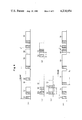
- FIG. 3 is a diagram showing an example of a TDMA burst signal for use in this invention.
- FIG. 4 is a timing chart explanatory of this invention.
- FIG. 5 is a block diagram showing an example of a control circuit for use in this invention.
- reference numeral 20 indicates a satellite; 21 designates an antenna site B; 22 identifies an antenna site A; 23 denotes a diversity control circuit; 24 represents a link line; 25 shows a TDMA terminal; and 26 refers to a signal line.
- a path B indicates a path from the diversity control circuit 23 to the satellite 20 via the link line 24 and the antenna site B, and a path A a path from the diversity control circuit 23 to the satellite 20 via the antenna site A.
- FIG. 2 illustrates an embodiment of the circuit construction of this invention.
- reference numeral 1 indicates an antenna of the antenna site A; 2 designates a transmitter; 3 identifies a receiver; 4 and 5 denote fixed digital delay circuits; 6 represents a control circuit for controlling the path length; 7 shows a route switching circuit for achieving the diversity operation; 8 refers to a TDMA terminal; 9 and 10 indicate variable delay circuits for controlling the path length of the path B; 23 designates the diversity control circuit 23 in FIG.
- 26-1 identifies a main signal line; 26-2 denotes a sub-burst sending line; 26-3 represents a burst position information sending line; 27a and 27b show a sending bus and a receiving bus respectively connected to the antenna 1 in the antenna site A; and 24a, 24b and 24c refer to a sending bus and a receiving bus in the link line 24 and a switching signal line.
- the control circuit 6 applies a route switching signal via the signal line 28 to the route switching circuit 7.
- a sending burst signal from the TDMA terminal is sent out from the antenna 1 to the satellite 20 via a path (A in the illustrated example) selected by the diversity switch circuit 7, the fixed delay circuit 4 and the transmitter 2 of the antenna site A.
- a burst signal received by the antenna 1 is demodulated by the receiver 3 to a PCM base-band signal and then applied to the TDMA terminal 8 via the fixed delay circuit 5 and the diversity switch circuit 7.
- the fixed delay circuits 4 and 5 are provided for compensating for a fixed path-length difference between the paths A and B and respectively have delay times obtained by calculation in advance during setting of the system.
- the path length of the path A excluding the link line 24 is made shorter than the path length of the path B.
- the variable delay circuits 9 and 10 are provided for compensating for fluctuations in the path-length difference between the both paths A and B which are caused by movements of the satellite 20 and path length fluctuations in the link line 24.
- FIG. 3 shows an example of the configuration of a TDMA burst signal in this invention.
- reference numeral 51 indicates a reference burst signal
- 52, 53 and 54 designate burst signals from different terrestrial stations.
- the sending timings of these bursts are controlled by the terrestrial stations so that the sent-out bursts may lie at predetermined positions relative to the reference burst signal 51.
- FIG. 3 shows a state in which the sending burst synchronization has already been established, and during operation of TDMA, the bursts must be sent out in time slots respectively assigned to the burst sending stations.
- Reference numeral 55 shows generally the contents of the reference burst signal 51; 56 indicates a pre-signal for carrier recovery and for bit timing regeneration necessary for the demodulation of a PCM signal; 57 designates a reference signal (i.e. a unique word) for burst synchronization; 58 identifies a portion assigned for the sending-out of control signals necessary for the operation of the TDMA system.
- Means for equalizing the receiving path lengths of the paths A and B detects a specified signal in the same burst from the receiving paths of the both antenna sites, for example, the reference signal for burst synchronization shown in FIG.
- the delay circuits 5 and 10 used in this example are digital delay circuits, so that in order to delay such a discontinuous signal as a burst signal, it is necessary to add a clock signal to the end of the burst signal for a period of time corresponding to the delay amount of the delay circuit.
- a signal converter included in the receiver 3 in FIG. 2 is used for delaying the signal. By the signal converter, clock signals of the received burst signal are replaced by a train of clock pulses of the station.
- a specific operative circuit construction for this operation is already set forth in detail in Japanese Pat. Appln. No. 147601/74.
- the determination of the burst sending timing for the sending burst synchronization is achieved by a burst synchronization circuit included in the TDMA terminal 8.
- the burst synchronization circuit is one usually employed in PCM-TDMA and performs the sending burst cynchronization using the unique word 57 included in the received signal and, in a case of reception, sends out the unique word detecting timing to the TDMA terminal 8 to provide the timing for the decoding of the received PCM signal.
- the received timings of the burst signal 53 sent out of the instant station and the reference burst signal 51 are compared with each other in the receiving side and the burst sending timing is corrected so that the burst signal sent out from the instant station lies in the slot assigned thereto.
- the burst sending timing is determined by measuring the position of the sent-out burst signal of the instant station by a distant station and returning therefrom the measured results.
- an approximate burst sending timing must be set so as not interfere with bursts of other stations in operation.
- This timing is usually set by an initial acquisition device associated with the TDMA terminal 8. That is, by using this device, the approximate sending timing is determined prior to the start of operation.
- an initial acquisition device associated with the TDMA terminal 8. that is, by using this device, the approximate sending timing is determined prior to the start of operation.
- there are several methods of this type and a typical one of them is to send out a low-speed signal at such a low level as not to interfere with bursts of other operating stations and determine the approximate sending timing from the receiving timing of the low-speed signal.
- an accurate sending timing required for the TDMA burst synchronization is still unobtainable.
- a preamble burst 62 (the hatched portion in FIG. 3), which is sufficiently shorter than the sent-out burst length, is sent out from the TDMA terminal 8 in the time slot assigned to the instant station.
- the preamble burst is sent out in the assigned time slot at a position which is sufficiently spaced away from the beginning of the time slot in consideration of the accuracy of measurement of the initial acquisition unit.
- the positional information of the preamble burst is sent back, and in the global-beam operation, by receiving the preamble burst by the instant station, the position of the sent-out preamble burst is confirmed. Further, the sent-out preamble burst position of the instant station is sequentially shifted to its normal position while being confirmed by the confirming means and, after completion of this operation, a data part is added to the end of the preamble burst, whereby communication is started.
- the above is the initial setting means for the sending burst synchronization in ordinary TDMA communication.
- the TDMA diversity two sending paths exist and, during path switching, the sending burst synchronization must be maintained, and consequently it is necessary that the both sending path lengths are electrically equal at the time of path switching.
- the path A passing through the antenna site A is a main path in operation, whereas the path B passing through the antenna site B is a stand-by path.
- the preamble burst 62 is sent out from the TDMA terminal 8 of FIG. 2 in the time slot 61 for the instant station burst in FIG. 4 via the diversity switching circuit 7, the fixed delay circuit 4, the transmitter 2 and the antenna 1.
- the preamble burst 62 is shifted to a predetermined position 62a in the assigned time slot according to the aforesaid sending burst synchronizing procedure.
- FIGS. 4(a) and (b) This operation is shown in FIGS. 4(a) and (b).
- the sending burst synchronization via the path A is already completed and a burst of the data part can be added.
- a sub-burst 63 which is delayed by a time ⁇ relative to the preamble burst 62 on the TDMA terminal, as shown in FIG. 4(d), is sent out to the path B.
- the sub-burst produced in the TDMA terminal 8 is sent out via the diversity switching circuit 7 and the variable delay circuit 9 to the satellite 20 from the antenna site B at the same frequency as the antenna site A.
- the time difference ⁇ between the both bursts is also retained on the satellite 20.
- a difference ⁇ can be detected by the reception of the bursts returned from the satellite, whereas in the spot-beam operation the difference can be detected by that information of detected reception timings of the preamble burst 62 and the sub-burst 63 which is sent back from a distant terrestrial station.
- the variable delay circuit 9 is controlled by a control signal from the control circuit 6 until the difference ⁇ is reduced to zero, as shown in FIG. 4(d). For example, if the difference ⁇ is +1 symbol length of the signal, the delay time of the variable delay circuit 9 is shortened by one symbol length.
- the path lengths of the both paths are set to be equal, so that the sub-burst 63 is sent out to the path B from a predetermined position in the sub-burst time slot indicated by 64 in FIG. 4(e) and a data part is added to the preamble burst sent out to the path A, thus starting communication. This state is shown in FIG. 4(e).
- the above is means for equalizing the path lengths of the both sending paths at the start of communication.
- a description will be given of means for equalizing the path lengths of the both sending paths during operation.
- the path lengths of the both sending paths fluctuate with the lapse of time due to fluctuations in the electrical length of the link line itself and movements of the satellite. Then, to achieve diversity, it is also necessary to equalize both path lengths during operation.
- the sending burst (a communication burst including a data part) of the instant station is sent out to the main path and the sub-burst is sent out to the stand-by path in the preset sub-burst time slot 64 in FIG. 4.
- the positional relationship between the sending burst and the sub-burst is known on the sending side, as indicated by ⁇ 0 in FIG. 4(e).
- variable delay circuit 9 is controlled to reduce the deviation to zero.
- a path-length difference between the both sending paths fluctuates very gently with movements of the satellite 20 or a change in the length of the link line, so that there is no need of sending out the sub-burst at all times.
- N the number of diversity stations accessible to the same satellite 20
- the time slot assigned to one sub-burst can be time shared by the N stations.
- each diversity terrestrial station detects the transmitted signal and, in accordance with a time schedule predetermined on the basis of the polarity inversion timing, each terrestrial station sends out the sub-burst to equalize the both path lengths.
- T time intervals of the pattern inversion of the synchronizing signal of the reference burst
- T/N time length which can be occupied by each terrestrial station for the equalization of the both path lengths
- a typical initial acquisition circuit will be described in connection with low-level initial acquisition.
- the initial acquisition circuit operates at a speed sufficiently lower than a signal speed.
- This circuit is composed of a PN signal generator which generates a signal at constant intervals, a PSK modem and a correlation detector.
- a signal transmitted from this circuit is deviated a little in frequency from a main signal.
- the receiving timing of this signal received via a satellite is measured by the correlator. As a result of this, the time of propagation between a terrestrial station and the satellite is determined on the basis of the sending timing and the receiving timing.
- the control circuit 6 produces a control signal for the diversity switch of the route switching circuit 7 which controls the delays of the variable delay circuits 9 and 10.
- a delay control signal is produced by detecting the path-length difference of both receiving paths using reference bursts from the both receiving paths immediately before the diversity changeover switch.
- a control signal for the variable delay circuit 9 for the equalization of the both sending path lengths is produced by burst position information from the TDMA terminal, that is, the information on the positional relationship between the instant station burst and the sub-burst.
- a diversity switch changeover signal is produced on the basis of switch changeover information, for example, the result of comparison of the received signal quality of the both receiving paths which is achieved by using the CN ratio (the received signal power vs. noise power ratio) of each path or the bit error rate measured in each path.
- the delay of the variable delay circuit 10 of the receiving side is determined by detecting a time difference between unique words of the reference bursts from the both receiving paths by unique word detectors 6-1a, 6-1b and a phase difference detector 6-2 immediately before the route switching circuit 7.
- Each of the unique word detector comprises a correlator.
- the path lengths are equalized by controlling the delay circuit 10 of the path B so that the position t a of the detected pulse in the path B coincides with the detected pulse position t b of the path A in terms of time.
- variable delay in the sending side is produced in the form of ( ⁇ l - ⁇ s ), by a variable delay control signal generator 6-3 comprising a counter counting clock pulses, on the basis of a deviation ( ⁇ l ) of the detected position of the instant station burst synchronizing signal from the TDMA terminal relative to a predetermined position of the instant station burst and a deviation ( ⁇ s ) of the detected position of the sub-burst synchronizing signal relative to a predetermined position of the auxiliary burst.
- the counter of the circuit 6-3 is reset by the prior one of ⁇ l , ⁇ s and counts clock pulses until the other of ⁇ l , ⁇ s is received to produce a result
- the polarity p is determined by detecting, by use of a flip-flop for example, which ( ⁇ l , ⁇ s ) is at first received.
- the path lengths are equalized by controlling the variable delay circuit 9 of the path B so that ⁇ l becomes equal to ⁇ s . In the event that the instant station burst or the sub-burst cannot be well received due to rain or the like, the variable delay control of the sending side follows that of the receiving side.
- a signal quality comparator 6-4 and a path switching signal generator 6-5 are the same as those employed in ordinary switching diversity. For instance, comparison of the received signal quality of two inputs from the receivers 3 and the line 24c is achieved in the signal quality comparator 6-4 by using the CN ratios or bit error rates of the both receiving paths and, based on the comparison result "1" or "0," a path selection signal is produced from the path switching signal generator 6-5 to select the site A or B.
- the fixed delay circuit and the variable delay circuits in FIG. 2 need not always be provided separately each other.
- the operation of this invention is exactly the same.
- the path B is a main path
- the sub-burst is naturally sent out to the path A, but equalization of the both sending paths is achieved by controlling the variable delay circuit 9 inserted in the path B.
- this invention enables, by the use of the sub-burst, easy and accurate equalization of the both sending path lengths at the time of path length setting of a diversity terrestrial station. Moreover, during operation, the path length equalization of a plurality of diversity terrestrial stations accessible to the same satellite and the sending burst synchronization during diversity operation can be performed easily and accurately only by setting the time slot for the sub-burst in one frame of TDMA. Hence, this invention is of great utility in the operation of the diversity system.
- this invention is also applicable to a space diversity using three or more antenna sites, by time sharing the sub-burst in the sending path forming each diversity.
Abstract
A space diversity system in a TDMA communication system employing a communication satellite, in which in order to equalize the path lengths of respective sending paths at the start of communication, a pre-burst is sent out to one of the paths making up the diversity system in a time slot of one frame assigned to an instant station. A sub-burst is sent out to the other of the paths in the assigned time slot. A relative time difference between the pre-burst and the sub-burst is detected from signals sent back to the instant station from the communication satellite or signals received by a distant terrestral station via the communication satellite. On the basis of the result of a comparison operation of relative time difference between the pre-burst and the sub-burst at the time of their sending-out from the instant station with a relative time difference between the pre-burst and the sub-burst received via the communication satellite, variable delay means inserted in one of the paths is controlled so that the two relative time differences become equal to each other.
Description
This invention relates to a space diversity system in a PCM-TDMA communication system.
With a recent demand for communications, frequency bands above 10 GHz are now going to come into use as satellite communications. In such high frequency regions, however, attenuation by rain is large to make it difficult to maintain satisfactory transmission quality when it rains. As a solution to this rain attenuation, the space diversity system is effective by the use of localization of a rain area. That is, since a heavy rain is localized upon a relatively narrow area, an excellent diversity effect can be expected if two antenna sites for achieving the space diversity are spaced more than 10 km apart.
In a case of carrying the diversity into practice, however, a distance between the two antenna sites is so large that a difference in path length between paths respectively passing through the two antenna sites includes a fixed path-length difference and a very gently varying path-length difference due to movements of a communication satellite (which is caused by the angle of inclination of an orbit of the communication satellite and its drift). Accordingly, even if signals for diversity are merely switched (or combined), a signal dropout or overlapping is caused by the difference between the both path lengths. Especially in a PCM-TDMA communication system, it is necessary to send the burst of each station in a predetermined time slot in one frame so as to achieve the burst synchronization. Therefore, in the diversity on the sending side, burst synchronizing means is of prime importance.
On the burst synchronizing means of the sending side, some studies have already been made in Japanese Pat. Applns. Nos. 13976/72, 33642/72 and 147602/74.
With the first one of the abovesaid prior applications, sending bursts are individually sent out every n (n=1, 2, 3, . . . ) frame or frames alternately from two antenna sites, thereby establishing burst synchronization, as a whole, as if the bursts are being sent out from one station. If the transmission quality of the sending route of one of the antenna sites is degraded by rain, a diversity operation takes place to improve the degraded transmission quality by immediately sending out all bursts from the other antenna site only when the rain attenuation of the other sending route is small and its signal quality is good.
With the second application, since the sending path length and the receiving path length from the respective antenna sites to the communication satellite have substantially the same fluctuation (which result from movements of the satellite), a difference between the both receiving path lengths is detected by using received signals from the both antenna sites, and on the basis of the detected path-length difference, a difference between the both sending path lengths is predicted. In the path switching for the diversity operation, the sending-out timing of the sending burst is determined by the use of the predicted value.
With the third application, in order that both receiving path lengths may be equal at the time of signal switching for diversity, a difference between the both receiving path lengths is detected from both received signals, and digital variable circuit or circuits inserted in the both sending paths and the both receiving paths or in one sending path and one receiving path is controlled by using the detected path-length difference to set the path lengths to be the same, and then the diversity operation is carried out.
In a case of the first application, it is necessary to generate the burst synchronization timing by some means when the system is switched from the diversity operation to a non-diversity one. Further, this requires a burst circuit for each antenna site, which makes it difficult to obtain an efficient diversity system.
The second and third applications are excellent in principle, but before the start of operation of the system, it is necessary to accurately measure the path-length difference between the sending path and the receiving path passing through each antenna site. In practice, however, this path-length difference may fluctuate with the lapse of time due to temperature change and so on, and in such a case, the accurate burst synchronization is not done. At any rate, in order to ensure the burst synchronization in the diversity operation, it is necessary that the lengths of the paths passing through the both antenna sites be electrically equalized.
An object of this invention is to provide a space diversity system for a TDMA communication system which facilitates equalization of the path lengths of sending paths respectively passing through two antenna sites, by a sub-burst, and which enables accurate and easy correction of a change in the path-length difference between the both sending paths during operation.
To achieve the above object, this invention comprises means for making the electrical path lengths of the both sending paths equal to each other in the course of initial acquisition operation, and means for maintaining the electrical path lengths of the both paths equal at all times during the operation, whereby the sending burst synchronization can be easily achieved also in the path switching accompanying the diversity operation.
In accordance with this invention, there is provided a space diversity system in a TDMA communication system employing a communication satellite; in which in order to equalize the path lengths of respective sending paths at the start of communication, a pre-burst is sent out to one of the paths making up the diversity system in a time slot of one frame assigned to an instant station; in which a sub-burst is sent out to the other of the paths in the assigned time slot; in which a relative time difference between the pre-burst and the sub-burst is detected from signals sent back to the instant station from the communication satellite or signals received by a distant terrestrial station via the communication satellite; and in which on the basis of the result of a comparison operation of a relative time difference between the pre-burst and the sub-burst at the time of their sending-out from the instant station with a relative time difference between the pre-burst and the sub-burst received via the communication satellite, variable delay means inserted in one of the paths is controlled so that the two relative time differences become equal to each other.
Moreover, after the path length equalization at the start of communication, a signal transmitting burst is sent out to a path in operation in the time slot assigned to the station, while a sub-burst is sent out to a stand-by path of diversity in a sub-burst time slot of the frame for each frame or on a time shared basis. A relative time difference between the signal transmitting burst and the sub-burst is detected from signals sent back to the station via the communication satellite. When the detected relative time difference is different from a predetermined relative time difference between the signal transmitting burst and the sub-burst at the time of their sending-out, variable delay circuit inserted in one of the paths is controlled so that the two relative time differences become equal to each other.
This invention will be described in detail below with reference to the accompanying drawings, in which:
FIG. 1 is a system diagram showing a space diversity system of a satellite communication system to which this invention is applies;
FIG. 2 is a block diagram illustrating an embodiment of this invention;
FIG. 3 is a diagram showing an example of a TDMA burst signal for use in this invention;
FIG. 4 is a timing chart explanatory of this invention; and
FIG. 5 is a block diagram showing an example of a control circuit for use in this invention.
With reference to FIG. 1 showing a TDMA space diversity system of a satellite communication system to which this invention, reference numeral 20 indicates a satellite; 21 designates an antenna site B; 22 identifies an antenna site A; 23 denotes a diversity control circuit; 24 represents a link line; 25 shows a TDMA terminal; and 26 refers to a signal line. A path B indicates a path from the diversity control circuit 23 to the satellite 20 via the link line 24 and the antenna site B, and a path A a path from the diversity control circuit 23 to the satellite 20 via the antenna site A.
FIG. 2 illustrates an embodiment of the circuit construction of this invention. In FIG. 2, reference numeral 1 indicates an antenna of the antenna site A; 2 designates a transmitter; 3 identifies a receiver; 4 and 5 denote fixed digital delay circuits; 6 represents a control circuit for controlling the path length; 7 shows a route switching circuit for achieving the diversity operation; 8 refers to a TDMA terminal; 9 and 10 indicate variable delay circuits for controlling the path length of the path B; 23 designates the diversity control circuit 23 in FIG. 1; 26-1 identifies a main signal line; 26-2 denotes a sub-burst sending line; 26-3 represents a burst position information sending line; 27a and 27b show a sending bus and a receiving bus respectively connected to the antenna 1 in the antenna site A; and 24a, 24b and 24c refer to a sending bus and a receiving bus in the link line 24 and a switching signal line. The control circuit 6 applies a route switching signal via the signal line 28 to the route switching circuit 7. In FIG. 2, a sending burst signal from the TDMA terminal is sent out from the antenna 1 to the satellite 20 via a path (A in the illustrated example) selected by the diversity switch circuit 7, the fixed delay circuit 4 and the transmitter 2 of the antenna site A. A burst signal received by the antenna 1 is demodulated by the receiver 3 to a PCM base-band signal and then applied to the TDMA terminal 8 via the fixed delay circuit 5 and the diversity switch circuit 7. The fixed delay circuits 4 and 5 are provided for compensating for a fixed path-length difference between the paths A and B and respectively have delay times obtained by calculation in advance during setting of the system. In the present embodiment, the path length of the path A excluding the link line 24 is made shorter than the path length of the path B. The variable delay circuits 9 and 10 are provided for compensating for fluctuations in the path-length difference between the both paths A and B which are caused by movements of the satellite 20 and path length fluctuations in the link line 24.
FIG. 3 shows an example of the configuration of a TDMA burst signal in this invention. In FIG. 3, reference numeral 51 indicates a reference burst signal, and 52, 53 and 54 designate burst signals from different terrestrial stations. The sending timings of these bursts are controlled by the terrestrial stations so that the sent-out bursts may lie at predetermined positions relative to the reference burst signal 51. Of course, FIG. 3 shows a state in which the sending burst synchronization has already been established, and during operation of TDMA, the bursts must be sent out in time slots respectively assigned to the burst sending stations. Reference numeral 55 shows generally the contents of the reference burst signal 51; 56 indicates a pre-signal for carrier recovery and for bit timing regeneration necessary for the demodulation of a PCM signal; 57 designates a reference signal (i.e. a unique word) for burst synchronization; 58 identifies a portion assigned for the sending-out of control signals necessary for the operation of the TDMA system. Means for equalizing the receiving path lengths of the paths A and B detects a specified signal in the same burst from the receiving paths of the both antenna sites, for example, the reference signal for burst synchronization shown in FIG. 3, and the delay of the variable delay circuit 10 is controlled so that the detecting timings are the same at the outputs of the variable delay circuits 5 and 10 in FIG. 2. The delay circuits 5 and 10 used in this example are digital delay circuits, so that in order to delay such a discontinuous signal as a burst signal, it is necessary to add a clock signal to the end of the burst signal for a period of time corresponding to the delay amount of the delay circuit. In practice, however, since the burst signal has not added thereto such a clock signal, a signal converter included in the receiver 3 in FIG. 2 is used for delaying the signal. By the signal converter, clock signals of the received burst signal are replaced by a train of clock pulses of the station. A specific operative circuit construction for this operation is already set forth in detail in Japanese Pat. Appln. No. 147601/74.
Next, a description will be given with respect to a specific operative example of the sending burst synchronization in this invention. The determination of the burst sending timing for the sending burst synchronization is achieved by a burst synchronization circuit included in the TDMA terminal 8. The burst synchronization circuit is one usually employed in PCM-TDMA and performs the sending burst cynchronization using the unique word 57 included in the received signal and, in a case of reception, sends out the unique word detecting timing to the TDMA terminal 8 to provide the timing for the decoding of the received PCM signal. In global beam operations, the received timings of the burst signal 53 sent out of the instant station and the reference burst signal 51 are compared with each other in the receiving side and the burst sending timing is corrected so that the burst signal sent out from the instant station lies in the slot assigned thereto. In a case of spot beam operation, the burst sending timing is determined by measuring the position of the sent-out burst signal of the instant station by a distant station and returning therefrom the measured results.
The above is the sending burst synchronizing means in the operation of the TDMA system. At the start of operation, an approximate burst sending timing must be set so as not interfere with bursts of other stations in operation. This timing is usually set by an initial acquisition device associated with the TDMA terminal 8. That is, by using this device, the approximate sending timing is determined prior to the start of operation. In practice, there are several methods of this type and a typical one of them is to send out a low-speed signal at such a low level as not to interfere with bursts of other operating stations and determine the approximate sending timing from the receiving timing of the low-speed signal. At this time, an accurate sending timing required for the TDMA burst synchronization is still unobtainable. Then, on the basis of this approximate measuring timing, only a preamble burst 62 (the hatched portion in FIG. 3), which is sufficiently shorter than the sent-out burst length, is sent out from the TDMA terminal 8 in the time slot assigned to the instant station. In this case, the preamble burst is sent out in the assigned time slot at a position which is sufficiently spaced away from the beginning of the time slot in consideration of the accuracy of measurement of the initial acquisition unit. In the case of the spot-beam operation, after the preamble burst is received by a distant terrestrial station, the positional information of the preamble burst is sent back, and in the global-beam operation, by receiving the preamble burst by the instant station, the position of the sent-out preamble burst is confirmed. Further, the sent-out preamble burst position of the instant station is sequentially shifted to its normal position while being confirmed by the confirming means and, after completion of this operation, a data part is added to the end of the preamble burst, whereby communication is started.
The above is the initial setting means for the sending burst synchronization in ordinary TDMA communication. In the TDMA diversity, two sending paths exist and, during path switching, the sending burst synchronization must be maintained, and consequently it is necessary that the both sending path lengths are electrically equal at the time of path switching.
Next, the operation of this invention will be concretely described. In the example of FIG. 2, the path A passing through the antenna site A is a main path in operation, whereas the path B passing through the antenna site B is a stand-by path. Let it be assumed that the approximate sending timing is determined by the initial acquisition unit in the path A. To establish the sending burst synchronization, the preamble burst 62 is sent out from the TDMA terminal 8 of FIG. 2 in the time slot 61 for the instant station burst in FIG. 4 via the diversity switching circuit 7, the fixed delay circuit 4, the transmitter 2 and the antenna 1. Next, the preamble burst 62 is shifted to a predetermined position 62a in the assigned time slot according to the aforesaid sending burst synchronizing procedure. This operation is shown in FIGS. 4(a) and (b). In the state of FIG. 4(b), the sending burst synchronization via the path A is already completed and a burst of the data part can be added. In this invention, a sub-burst 63 which is delayed by a time τ relative to the preamble burst 62 on the TDMA terminal, as shown in FIG. 4(d), is sent out to the path B. Namely, the sub-burst produced in the TDMA terminal 8 is sent out via the diversity switching circuit 7 and the variable delay circuit 9 to the satellite 20 from the antenna site B at the same frequency as the antenna site A. In this instance, if the both path lengths from the TDMA terminal 8 are equal to each other, the time difference τ between the both bursts is also retained on the satellite 20. As depicted in FIG. 4(c), if the both path lengths are not the same, there exists a difference τ' between the both bursts received by the satellite 20, and a difference τ'-τ=Δτ corresponds to the path-length difference between the both paths. In practice, in the global-beam operation a difference Δτ can be detected by the reception of the bursts returned from the satellite, whereas in the spot-beam operation the difference can be detected by that information of detected reception timings of the preamble burst 62 and the sub-burst 63 which is sent back from a distant terrestrial station. As a result of this, if the difference Δτ is detected, the variable delay circuit 9 is controlled by a control signal from the control circuit 6 until the difference Δτ is reduced to zero, as shown in FIG. 4(d). For example, if the difference Δτ is +1 symbol length of the signal, the delay time of the variable delay circuit 9 is shortened by one symbol length. As a consequence, the path lengths of the both paths are set to be equal, so that the sub-burst 63 is sent out to the path B from a predetermined position in the sub-burst time slot indicated by 64 in FIG. 4(e) and a data part is added to the preamble burst sent out to the path A, thus starting communication. This state is shown in FIG. 4(e).
The above is means for equalizing the path lengths of the both sending paths at the start of communication. Next, a description will be given of means for equalizing the path lengths of the both sending paths during operation. In the diversity system, as the two antenna sites are interconnected via a link line, the path lengths of the both sending paths fluctuate with the lapse of time due to fluctuations in the electrical length of the link line itself and movements of the satellite. Then, to achieve diversity, it is also necessary to equalize both path lengths during operation.
As described above, the sending burst (a communication burst including a data part) of the instant station is sent out to the main path and the sub-burst is sent out to the stand-by path in the preset sub-burst time slot 64 in FIG. 4. The positional relationship between the sending burst and the sub-burst is known on the sending side, as indicated by τ0 in FIG. 4(e). Accordingly, if the positional relationship between the sending burst and the sub-burst sent out from the instant station is detected to be deviated from τ0, by means similar to the aforementioned one, after receiving the relative positions of the both bursts in the global-beam operation or on the basis of information sent back from a distant terrestrial station in the slot-beam operation, the variable delay circuit 9 is controlled to reduce the deviation to zero.
Usually, a path-length difference between the both sending paths fluctuates very gently with movements of the satellite 20 or a change in the length of the link line, so that there is no need of sending out the sub-burst at all times. This means that if the number of diversity stations accessible to the same satellite 20 is N, the time slot assigned to one sub-burst can be time shared by the N stations. An example will be described. Now, let it be assumed that a reference station which is sending a reference burst transmits the burst whose reference synchronizing signal pattern composed of "1" and "0" is inverted at certain time intervals. Then, each diversity terrestrial station detects the transmitted signal and, in accordance with a time schedule predetermined on the basis of the polarity inversion timing, each terrestrial station sends out the sub-burst to equalize the both path lengths. In this instance, letting the time intervals of the pattern inversion of the synchronizing signal of the reference burst be represented by T (sec), the time length which can be occupied by each terrestrial station for the equalization of the both path lengths is T/N (sec).
A typical initial acquisition circuit will be described in connection with low-level initial acquisition. The initial acquisition circuit operates at a speed sufficiently lower than a signal speed. This circuit is composed of a PN signal generator which generates a signal at constant intervals, a PSK modem and a correlation detector. A signal transmitted from this circuit is deviated a little in frequency from a main signal. The receiving timing of this signal received via a satellite is measured by the correlator. As a result of this, the time of propagation between a terrestrial station and the satellite is determined on the basis of the sending timing and the receiving timing.
The control circuit 6 produces a control signal for the diversity switch of the route switching circuit 7 which controls the delays of the variable delay circuits 9 and 10. A delay control signal is produced by detecting the path-length difference of both receiving paths using reference bursts from the both receiving paths immediately before the diversity changeover switch. A control signal for the variable delay circuit 9 for the equalization of the both sending path lengths is produced by burst position information from the TDMA terminal, that is, the information on the positional relationship between the instant station burst and the sub-burst. A diversity switch changeover signal is produced on the basis of switch changeover information, for example, the result of comparison of the received signal quality of the both receiving paths which is achieved by using the CN ratio (the received signal power vs. noise power ratio) of each path or the bit error rate measured in each path.
That is, the delay of the variable delay circuit 10 of the receiving side is determined by detecting a time difference between unique words of the reference bursts from the both receiving paths by unique word detectors 6-1a, 6-1b and a phase difference detector 6-2 immediately before the route switching circuit 7. Each of the unique word detector comprises a correlator. The path lengths are equalized by controlling the delay circuit 10 of the path B so that the position ta of the detected pulse in the path B coincides with the detected pulse position tb of the path A in terms of time.
The variable delay in the sending side is produced in the form of (Δφl -Δφs), by a variable delay control signal generator 6-3 comprising a counter counting clock pulses, on the basis of a deviation (Δφl) of the detected position of the instant station burst synchronizing signal from the TDMA terminal relative to a predetermined position of the instant station burst and a deviation (Δφs) of the detected position of the sub-burst synchronizing signal relative to a predetermined position of the auxiliary burst. The counter of the circuit 6-3 is reset by the prior one of Δφl, Δφs and counts clock pulses until the other of Δφl, Δφs is received to produce a result |Δφl -Δφs |. The polarity p is determined by detecting, by use of a flip-flop for example, which (Δφl, Δφs) is at first received. The path lengths are equalized by controlling the variable delay circuit 9 of the path B so that Δφl becomes equal to Δφs. In the event that the instant station burst or the sub-burst cannot be well received due to rain or the like, the variable delay control of the sending side follows that of the receiving side.
A signal quality comparator 6-4 and a path switching signal generator 6-5 are the same as those employed in ordinary switching diversity. For instance, comparison of the received signal quality of two inputs from the receivers 3 and the line 24c is achieved in the signal quality comparator 6-4 by using the CN ratios or bit error rates of the both receiving paths and, based on the comparison result "1" or "0," a path selection signal is produced from the path switching signal generator 6-5 to select the site A or B.
The above has described this invention in detail with respect to its specific operative embodiment, but the fixed delay circuit and the variable delay circuits in FIG. 2 need not always be provided separately each other. For example, even where the fixed delay circuit and the variable delay circuits are connected in series and only the variable delay circuits are controlled for the path length equalization, the operation of this invention is exactly the same. Further, when the path B is a main path, the sub-burst is naturally sent out to the path A, but equalization of the both sending paths is achieved by controlling the variable delay circuit 9 inserted in the path B.
As has been described in the foregoing, this invention enables, by the use of the sub-burst, easy and accurate equalization of the both sending path lengths at the time of path length setting of a diversity terrestrial station. Moreover, during operation, the path length equalization of a plurality of diversity terrestrial stations accessible to the same satellite and the sending burst synchronization during diversity operation can be performed easily and accurately only by setting the time slot for the sub-burst in one frame of TDMA. Hence, this invention is of great utility in the operation of the diversity system.
Besides, it is needless to say that this invention is also applicable to a space diversity using three or more antenna sites, by time sharing the sub-burst in the sending path forming each diversity.
Claims (2)
1. A space diversity system in a TDMA communication system employing a communication satellite including: equalizing means for equalizing the path lengths of respective sending paths at the start of communication; said equalizing means comprising pre-burst sending means for sending a pre-burst out to one of the paths making up the diversity system in a time slot of one frame assigned to an instant station; sub-burst sending means for sending a sub-burst out to the other of the paths in the assigned time slot; time difference detecting means for detecting a relative time difference between the pre-burst and the sub-burst from signals sent back to the instant station from the communication satellite or signals received by a distant terrestrial station via the communication satellite; comparison means for comparing a relative time difference between the pre-burst and the sub-burst at the time of their sending-out from the instant station with a relative time difference between the pre-burst and the sub-burst received via the communication satellite; and variable delay means inserted in one of the paths and controlled by said comparison means so that the two relative time differences become equal to each other.
2. A space diversity system in a TDMA communication system employing a communication satellite including: equalizing means for equalizing the path lengths of respective sending paths at the start of communication; said equalizing means comprising pre-burst sending means for sending a pre-burst out to one of the paths making up the diversity system in a time slot of one frame assigned to an instant station; sub-burst sending means for sending a sub-burst out to the other of the paths in the assigned time slot; time distance detecting means for detecting a relative time difference between the pre-burst and the sub-burst from signals sent back to the instant station from the communication satellite or signals received by a distant terrestrial station via the communication satellite; comparison means for comparing a relative time difference between the pre-burst and the sub-burst at the time of their sending-out from the instant station with a relative time difference between the pre-burst and the sub-burst received via the communication satellite, variable delay means inserted in one of the paths and controlled by said comparison means so that the two relative time differences become equal to each other; wherein after the path length equalization at the start of communication, a signal transmitting burst is sent out to a path in operation in the time slot assigned to the station, while a sub-burst is sent out to a stand-by path of diversity in a sub-burst time slot of the frame for each frame or on a time shared basis; wherein relative time difference between the signal transmitting burst and sub-burst is detected from signals sent back to the station via the communication satellite; and wherein when the detected relative time difference is different from a predetermined relative time difference between the signal transmitting burst and the sub-burst at the time of their sending-out, said variable delay means inserted in one of the paths is controlled so that the two relative time differences become equal to each other.
Applications Claiming Priority (2)
| Application Number | Priority Date | Filing Date | Title |
|---|---|---|---|
| JP5127278A JPS54143009A (en) | 1978-04-28 | 1978-04-28 | Space diversity system for tdma communication system |
| JP53-51272 | 1978-04-28 |
Publications (1)
| Publication Number | Publication Date |
|---|---|
| US4218654A true US4218654A (en) | 1980-08-19 |
Family
ID=12882305
Family Applications (1)
| Application Number | Title | Priority Date | Filing Date |
|---|---|---|---|
| US06/013,287 Expired - Lifetime US4218654A (en) | 1978-04-28 | 1979-02-21 | Space diversity system in TDMA communication system |
Country Status (10)
| Country | Link |
|---|---|
| US (1) | US4218654A (en) |
| JP (1) | JPS54143009A (en) |
| BE (1) | BE875909A (en) |
| CA (1) | CA1130026A (en) |
| DE (1) | DE2916602C3 (en) |
| FR (1) | FR2424673A1 (en) |
| GB (1) | GB2022369B (en) |
| IT (1) | IT1164674B (en) |
| NL (1) | NL183692C (en) |
| SE (1) | SE440576B (en) |
Cited By (63)
| Publication number | Priority date | Publication date | Assignee | Title |
|---|---|---|---|---|
| US4287598A (en) * | 1979-12-17 | 1981-09-01 | Bell Telephone Laboratories, Incorporated | Cooperating arrangement for diversity stations |
| US4481647A (en) * | 1981-05-15 | 1984-11-06 | Tektronix, Inc. | Method and apparatus of compensating for variations in signal propagation time existing within the channels of a multi-channel device |
| US4607257A (en) * | 1981-12-25 | 1986-08-19 | Nippon Electric Co. Ltd. | Remote calibrating system for satellite time |
| US4630289A (en) * | 1979-12-21 | 1986-12-16 | Wren Paul E | Emergency locator transmitter incident time correlator |
| US4630267A (en) * | 1983-12-23 | 1986-12-16 | International Business Machines Corporation | Programmable timing and synchronization circuit for a TDMA communications controller |
| WO1987005169A1 (en) * | 1986-02-13 | 1987-08-27 | Signatron, Inc. | Signal processing system |
| US4696051A (en) * | 1985-12-31 | 1987-09-22 | Motorola Inc. | Simulcast transmission system having automtic synchronization |
| US4696052A (en) * | 1985-12-31 | 1987-09-22 | Motorola Inc. | Simulcast transmitter apparatus having automatic synchronization capability |
| US4805196A (en) * | 1987-04-29 | 1989-02-14 | Gte Laboratories Incorporated | Line delay compensation for digital transmission systems utilizing low power line drivers |
| EP0396101A2 (en) * | 1989-05-02 | 1990-11-07 | Nec Corporation | Space diversity TDMA receiver |
| US4972410A (en) * | 1989-07-20 | 1990-11-20 | Electrocom Automation, Inc. | Method and apparatus for controlling signal coherency in simulcast systems |
| US5117424A (en) * | 1989-07-20 | 1992-05-26 | Electrocom Automation L.P. | Method and apparatus for setting clock signals to predetermined phases at remote broadcast sites in simulcast systems |
| US5172396A (en) * | 1988-10-20 | 1992-12-15 | General Electric Company | Public service trunking simulcast system |
| WO1993006663A1 (en) * | 1991-09-27 | 1993-04-01 | Motorola, Inc. | Data packet alignment in a communication system |
| US5239541A (en) * | 1990-01-31 | 1993-08-24 | Mitsubishi Denki Kabushiki Kaisha | Antenna selection diversity reception apparatus |
| US5321727A (en) * | 1990-04-27 | 1994-06-14 | U.S. Philips Corporation | Signal phasing arrangement in a system for doubling the digital channel |
| US5477539A (en) * | 1993-07-23 | 1995-12-19 | Ericsson Inc. | Narrow band simulcast system having low speed data distribution |
| WO1996003814A1 (en) * | 1994-07-22 | 1996-02-08 | International Mobile Satellite Organization | Multi-beam tdma satellite mobile communications system |
| US5517680A (en) * | 1992-01-22 | 1996-05-14 | Ericsson Inc. | Self correction of PST simulcast system timing |
| US5546425A (en) * | 1994-02-02 | 1996-08-13 | Lucent Technologies Inc. | Transmission system for transmitting data by a link comprising intermediate equipments and an intermediate equipment for such a system |
| US5594761A (en) * | 1992-06-30 | 1997-01-14 | Ericsson Inc. | Control channel timing detection and self correction for digitally trunked simulcast radio communications system |
| FR2737627A1 (en) * | 1995-08-02 | 1997-02-07 | Europ Agence Spatiale | RADIO SIGNAL TRANSMISSION SYSTEM VIA A GEOSTATIONARY COMMUNICATION SATELLITE, IN PARTICULAR FOR COMMUNICATIONS WITH PORTABLE MOBILE TERMINALS |
| US5613195A (en) * | 1993-05-12 | 1997-03-18 | Nec Corporation | Burst output timing control system in satellite communication system |
| WO1997011536A1 (en) * | 1995-09-22 | 1997-03-27 | Qualcomm Incorporated | Method and apparatus for diversity enhancement using pseudo-multipath signals |
| US5742907A (en) * | 1995-07-19 | 1998-04-21 | Ericsson Inc. | Automatic clear voice and land-line backup alignment for simulcast system |
| US5790939A (en) * | 1995-06-29 | 1998-08-04 | Hughes Electronics Corporation | Method and system of frame timing synchronization in TDMA based mobile satellite communication system |
| US5805645A (en) * | 1992-06-30 | 1998-09-08 | Ericsson Inc. | Control channel synchronization between DBC and Cellular networks |
| WO1998052300A2 (en) * | 1997-05-13 | 1998-11-19 | Qualcomm Incorporated | System and method for detection and selection of multiple antenna |
| US5842134A (en) * | 1995-09-28 | 1998-11-24 | Ericsson Inc. | Auto-alignment of clear voice and low speed digital data signals in a simulcast system |
| US5899957A (en) * | 1994-01-03 | 1999-05-04 | Trimble Navigation, Ltd. | Carrier phase differential GPS corrections network |
| WO2000008780A1 (en) * | 1998-08-04 | 2000-02-17 | Tachyon, Inc. | Method of and apparatus for time synchronisation in a communication system |
| US6154456A (en) * | 1995-08-25 | 2000-11-28 | Terayon Communication Systems, Inc. | Apparatus and method for digital data transmission using orthogonal codes |
| EP1107484A1 (en) * | 1999-06-17 | 2001-06-13 | Mitsubishi Denki Kabushiki Kaisha | Mobile communication system |
| US6307868B1 (en) | 1995-08-25 | 2001-10-23 | Terayon Communication Systems, Inc. | Apparatus and method for SCDMA digital data transmission using orthogonal codes and a head end modem with no tracking loops |
| WO2002009318A2 (en) * | 2000-07-26 | 2002-01-31 | Ericsson Inc. | Satellite communications system using multiple earth stations |
| US20020015424A1 (en) * | 1997-05-19 | 2002-02-07 | Preston Daniel A. | Network delay identification method and apparatus |
| US6356555B1 (en) | 1995-08-25 | 2002-03-12 | Terayon Communications Systems, Inc. | Apparatus and method for digital data transmission using orthogonal codes |
| US20020097706A1 (en) * | 1997-05-19 | 2002-07-25 | Preston Dan A. | In-band signaling for data communications over digital wireless telecommunications networks |
| US20020132579A1 (en) * | 1994-07-22 | 2002-09-19 | International Mobile Satellite Organization | Multi-beam TDMA satellite mobile communications system |
| US6574461B1 (en) * | 1997-06-19 | 2003-06-03 | Telefonaktiebolaget Lm Ericsson (Publ) | Balanced diversity |
| US6665308B1 (en) | 1995-08-25 | 2003-12-16 | Terayon Communication Systems, Inc. | Apparatus and method for equalization in distributed digital data transmission systems |
| US20040056796A1 (en) * | 2002-09-24 | 2004-03-25 | Honeywell International Inc. | Method and system for compensating satellite signals |
| US20040058645A1 (en) * | 2002-09-24 | 2004-03-25 | Honeywell International Inc. | Radio frequency interference monitor |
| WO2004030237A2 (en) * | 2002-09-24 | 2004-04-08 | Honeywell International Inc. | Method and system for compensating satellite signals |
| US6771629B1 (en) | 1999-01-15 | 2004-08-03 | Airbiquity Inc. | In-band signaling for synchronization in a voice communications network |
| US6799116B2 (en) | 2000-12-15 | 2004-09-28 | Trimble Navigation Limited | GPS correction methods, apparatus and signals |
| US20060064244A1 (en) * | 1994-01-03 | 2006-03-23 | Robbins James E | Differential GPS corrections using virtual stations |
| US7283567B2 (en) | 2001-06-22 | 2007-10-16 | Airbiquity Inc. | Network delay identification method and apparatus |
| US7283569B2 (en) | 1999-12-20 | 2007-10-16 | Kabushiki Kaisha Kenwood | Site delivery method, method for receiving digital satellite broadcast, and receiver for digital satellite broadcast |
| US7286522B2 (en) | 1998-05-19 | 2007-10-23 | Airbiquity, Inc. | Synchronizer for use with improved in-band signaling for data communications over digital wireless telecommunications networks |
| US20070264964A1 (en) * | 2006-04-07 | 2007-11-15 | Airbiquity, Inc. | Time diversity voice channel data communications |
| US20090117947A1 (en) * | 2007-10-20 | 2009-05-07 | Airbiquity Inc. | Wireless in-band signaling with in-vehicle systems |
| US20090149196A1 (en) * | 2001-11-01 | 2009-06-11 | Airbiquity Inc. | Method for pulling geographic location data from a remote wireless telecommunications mobile unit |
| US20090154444A1 (en) * | 2005-01-31 | 2009-06-18 | Airbiquity Inc. | Voice channel control of wireless packet data communications |
| US20100035570A1 (en) * | 2007-02-06 | 2010-02-11 | Panasonic Corporation | Receiver and receiving system using the same |
| US20100273470A1 (en) * | 2009-04-27 | 2010-10-28 | Airbiquity Inc. | Automatic gain control in a personal navigation device |
| US20110125488A1 (en) * | 2009-11-23 | 2011-05-26 | Airbiquity Inc. | Adaptive data transmission for a digital in-band modem operating over a voice channel |
| US7983310B2 (en) | 2008-09-15 | 2011-07-19 | Airbiquity Inc. | Methods for in-band signaling through enhanced variable-rate codecs |
| US8418039B2 (en) | 2009-08-03 | 2013-04-09 | Airbiquity Inc. | Efficient error correction scheme for data transmission in a wireless in-band signaling system |
| US8594138B2 (en) | 2008-09-15 | 2013-11-26 | Airbiquity Inc. | Methods for in-band signaling through enhanced variable-rate codecs |
| US8848825B2 (en) | 2011-09-22 | 2014-09-30 | Airbiquity Inc. | Echo cancellation in wireless inband signaling modem |
| US10985834B2 (en) * | 2017-04-26 | 2021-04-20 | Lynk Global, Inc. | Method and apparatus for handling communications between spacecraft operating in an orbital environment and terrestrial telecommunications devices that use terrestrial base station communications |
| US11863250B2 (en) | 2021-01-06 | 2024-01-02 | Lynk Global, Inc. | Satellite communication system transmitting navigation signals using a wide beam and data signals using a directive beam |
Families Citing this family (4)
| Publication number | Priority date | Publication date | Assignee | Title |
|---|---|---|---|---|
| FR2502426A1 (en) * | 1981-03-20 | 1982-09-24 | Trt Telecom Radio Electr | SYSTEM FOR TRANSMITTING INFORMATION BETWEEN A MAIN STATION AND SECONDARY STATIONS OPERATING IN ACCORDANCE WITH A TDMA METHOD |
| JPS6469907A (en) * | 1987-09-11 | 1989-03-15 | Nippon Avionics Co Ltd | Method for detecting three-dimensional positional shift of rod-shaped body |
| FI934875A (en) * | 1993-11-04 | 1995-05-05 | Nokia Telecommunications Oy | A method for transmitting radio frequency signals and a TDMA transceiver |
| CN109584546B (en) * | 2018-07-04 | 2021-06-01 | 东南大学 | Method for determining departure flow threshold of quick-conventional bus sharing lane |
Citations (4)
| Publication number | Priority date | Publication date | Assignee | Title |
|---|---|---|---|---|
| US3418579A (en) * | 1964-09-08 | 1968-12-24 | Comm And Systems Inc | Satellite communication synchronizing system |
| US3654395A (en) * | 1969-10-15 | 1972-04-04 | Communications Satellite Corp | Synchronization of tdma space division satellite system |
| US4107608A (en) * | 1975-12-10 | 1978-08-15 | Nippon Electric Co., Ltd. | Method and apparatus for burst synchronization in a time division multiple access communication system |
| US4129755A (en) * | 1976-11-11 | 1978-12-12 | Nippon Electric Co., Ltd. | Frame synchronizing system for TDMA radio communications |
-
1978
- 1978-04-28 JP JP5127278A patent/JPS54143009A/en active Granted
-
1979
- 1979-02-21 US US06/013,287 patent/US4218654A/en not_active Expired - Lifetime
- 1979-03-05 GB GB7907620A patent/GB2022369B/en not_active Expired
- 1979-03-09 CA CA323,075A patent/CA1130026A/en not_active Expired
- 1979-03-26 FR FR7907559A patent/FR2424673A1/en active Granted
- 1979-04-06 NL NLAANVRAGE7902734,A patent/NL183692C/en not_active IP Right Cessation
- 1979-04-24 DE DE2916602A patent/DE2916602C3/en not_active Expired
- 1979-04-26 IT IT48849/79A patent/IT1164674B/en active
- 1979-04-27 BE BE2/57761A patent/BE875909A/en not_active IP Right Cessation
- 1979-04-27 SE SE7903715A patent/SE440576B/en not_active IP Right Cessation
Patent Citations (4)
| Publication number | Priority date | Publication date | Assignee | Title |
|---|---|---|---|---|
| US3418579A (en) * | 1964-09-08 | 1968-12-24 | Comm And Systems Inc | Satellite communication synchronizing system |
| US3654395A (en) * | 1969-10-15 | 1972-04-04 | Communications Satellite Corp | Synchronization of tdma space division satellite system |
| US4107608A (en) * | 1975-12-10 | 1978-08-15 | Nippon Electric Co., Ltd. | Method and apparatus for burst synchronization in a time division multiple access communication system |
| US4129755A (en) * | 1976-11-11 | 1978-12-12 | Nippon Electric Co., Ltd. | Frame synchronizing system for TDMA radio communications |
Cited By (116)
| Publication number | Priority date | Publication date | Assignee | Title |
|---|---|---|---|---|
| US4287598A (en) * | 1979-12-17 | 1981-09-01 | Bell Telephone Laboratories, Incorporated | Cooperating arrangement for diversity stations |
| US4630289A (en) * | 1979-12-21 | 1986-12-16 | Wren Paul E | Emergency locator transmitter incident time correlator |
| US4481647A (en) * | 1981-05-15 | 1984-11-06 | Tektronix, Inc. | Method and apparatus of compensating for variations in signal propagation time existing within the channels of a multi-channel device |
| US4607257A (en) * | 1981-12-25 | 1986-08-19 | Nippon Electric Co. Ltd. | Remote calibrating system for satellite time |
| US4630267A (en) * | 1983-12-23 | 1986-12-16 | International Business Machines Corporation | Programmable timing and synchronization circuit for a TDMA communications controller |
| US4696051A (en) * | 1985-12-31 | 1987-09-22 | Motorola Inc. | Simulcast transmission system having automtic synchronization |
| US4696052A (en) * | 1985-12-31 | 1987-09-22 | Motorola Inc. | Simulcast transmitter apparatus having automatic synchronization capability |
| US4805189A (en) * | 1986-02-13 | 1989-02-14 | Signatron, Inc. | Signal processing system |
| WO1987005169A1 (en) * | 1986-02-13 | 1987-08-27 | Signatron, Inc. | Signal processing system |
| US4805196A (en) * | 1987-04-29 | 1989-02-14 | Gte Laboratories Incorporated | Line delay compensation for digital transmission systems utilizing low power line drivers |
| US5172396A (en) * | 1988-10-20 | 1992-12-15 | General Electric Company | Public service trunking simulcast system |
| EP0396101A3 (en) * | 1989-05-02 | 1992-09-30 | Nec Corporation | Space diversity tdma receiver |
| EP0396101A2 (en) * | 1989-05-02 | 1990-11-07 | Nec Corporation | Space diversity TDMA receiver |
| US5117424A (en) * | 1989-07-20 | 1992-05-26 | Electrocom Automation L.P. | Method and apparatus for setting clock signals to predetermined phases at remote broadcast sites in simulcast systems |
| US4972410A (en) * | 1989-07-20 | 1990-11-20 | Electrocom Automation, Inc. | Method and apparatus for controlling signal coherency in simulcast systems |
| US5239541A (en) * | 1990-01-31 | 1993-08-24 | Mitsubishi Denki Kabushiki Kaisha | Antenna selection diversity reception apparatus |
| US5321727A (en) * | 1990-04-27 | 1994-06-14 | U.S. Philips Corporation | Signal phasing arrangement in a system for doubling the digital channel |
| WO1993006663A1 (en) * | 1991-09-27 | 1993-04-01 | Motorola, Inc. | Data packet alignment in a communication system |
| US5268933A (en) * | 1991-09-27 | 1993-12-07 | Motorola, Inc. | Data packet alignment in a communication system |
| GB2268367A (en) * | 1991-09-27 | 1994-01-05 | Motorola Inc | Data packet alignment in a communication system |
| GB2268367B (en) * | 1991-09-27 | 1996-06-05 | Motorola Inc | Data packet alignment in a communication system |
| US5517680A (en) * | 1992-01-22 | 1996-05-14 | Ericsson Inc. | Self correction of PST simulcast system timing |
| US5594761A (en) * | 1992-06-30 | 1997-01-14 | Ericsson Inc. | Control channel timing detection and self correction for digitally trunked simulcast radio communications system |
| US5805645A (en) * | 1992-06-30 | 1998-09-08 | Ericsson Inc. | Control channel synchronization between DBC and Cellular networks |
| US5613195A (en) * | 1993-05-12 | 1997-03-18 | Nec Corporation | Burst output timing control system in satellite communication system |
| US5477539A (en) * | 1993-07-23 | 1995-12-19 | Ericsson Inc. | Narrow band simulcast system having low speed data distribution |
| US7711480B2 (en) | 1994-01-03 | 2010-05-04 | Trimble Navigation Limited | Differential GPS corrections using virtual stations |
| US20060282216A1 (en) * | 1994-01-03 | 2006-12-14 | Robbins James E | Differential GPS corrections using virtual stations |
| US20060064244A1 (en) * | 1994-01-03 | 2006-03-23 | Robbins James E | Differential GPS corrections using virtual stations |
| US5899957A (en) * | 1994-01-03 | 1999-05-04 | Trimble Navigation, Ltd. | Carrier phase differential GPS corrections network |
| US5546425A (en) * | 1994-02-02 | 1996-08-13 | Lucent Technologies Inc. | Transmission system for transmitting data by a link comprising intermediate equipments and an intermediate equipment for such a system |
| US20020132579A1 (en) * | 1994-07-22 | 2002-09-19 | International Mobile Satellite Organization | Multi-beam TDMA satellite mobile communications system |
| CN1080958C (en) * | 1994-07-22 | 2002-03-13 | 英马尔塞特有限公司 | Multi-beam TDMA satellite mobile communication system |
| WO1996003814A1 (en) * | 1994-07-22 | 1996-02-08 | International Mobile Satellite Organization | Multi-beam tdma satellite mobile communications system |
| US20020061730A1 (en) * | 1994-07-22 | 2002-05-23 | Nicholas Hart | Multi-beam TDMA satellite mobile communications system |
| US6314269B1 (en) | 1994-07-22 | 2001-11-06 | International Mobile Satelitte Organization | Multi-beam TDMA satellite mobile communications system |
| US5790939A (en) * | 1995-06-29 | 1998-08-04 | Hughes Electronics Corporation | Method and system of frame timing synchronization in TDMA based mobile satellite communication system |
| US5742907A (en) * | 1995-07-19 | 1998-04-21 | Ericsson Inc. | Automatic clear voice and land-line backup alignment for simulcast system |
| US5839053A (en) * | 1995-08-02 | 1998-11-17 | Agence Spatiale Europeene | System for transmitting radio signals from mobile terminals to provide space diversity for uplink signals via geostationary communication satellites |
| FR2737627A1 (en) * | 1995-08-02 | 1997-02-07 | Europ Agence Spatiale | RADIO SIGNAL TRANSMISSION SYSTEM VIA A GEOSTATIONARY COMMUNICATION SATELLITE, IN PARTICULAR FOR COMMUNICATIONS WITH PORTABLE MOBILE TERMINALS |
| US6307868B1 (en) | 1995-08-25 | 2001-10-23 | Terayon Communication Systems, Inc. | Apparatus and method for SCDMA digital data transmission using orthogonal codes and a head end modem with no tracking loops |
| US6154456A (en) * | 1995-08-25 | 2000-11-28 | Terayon Communication Systems, Inc. | Apparatus and method for digital data transmission using orthogonal codes |
| US7239650B2 (en) | 1995-08-25 | 2007-07-03 | Terayon Communication Systems, Inc. | Apparatus and method for receiving upstream data transmissions from multiple remote transmitters |
| US7095707B2 (en) | 1995-08-25 | 2006-08-22 | Terayon Communication Systems, Inc. | Apparatus and method for trellis encoding data for transmission in digital data transmission systems |
| US6356555B1 (en) | 1995-08-25 | 2002-03-12 | Terayon Communications Systems, Inc. | Apparatus and method for digital data transmission using orthogonal codes |
| US7031344B2 (en) | 1995-08-25 | 2006-04-18 | Terayon Communication Systems, Inc. | Apparatus and method for SCDMA digital data transmission using orthogonal codes and a head end modem with no tracking loops |
| US7020165B2 (en) | 1995-08-25 | 2006-03-28 | Terayon Communication Systems, Inc | Apparatus and method for trellis encoding data for transmission in digital data transmission systems |
| US6937617B2 (en) | 1995-08-25 | 2005-08-30 | Terayon Communication System, Inc. | Apparatus and method for trellis encoding data for transmission in digital data transmission systems |
| US6665308B1 (en) | 1995-08-25 | 2003-12-16 | Terayon Communication Systems, Inc. | Apparatus and method for equalization in distributed digital data transmission systems |
| US5991345A (en) * | 1995-09-22 | 1999-11-23 | Qualcomm Incorporated | Method and apparatus for diversity enhancement using pseudo-multipath signals |
| WO1997011536A1 (en) * | 1995-09-22 | 1997-03-27 | Qualcomm Incorporated | Method and apparatus for diversity enhancement using pseudo-multipath signals |
| US5842134A (en) * | 1995-09-28 | 1998-11-24 | Ericsson Inc. | Auto-alignment of clear voice and low speed digital data signals in a simulcast system |
| KR100585307B1 (en) * | 1997-05-13 | 2006-06-01 | 퀄컴 인코포레이티드 | System and method for detection and selection of multiple antenna |
| WO1998052300A3 (en) * | 1997-05-13 | 1999-04-22 | Qualcomm Inc | System and method for detection and selection of multiple antenna |
| AU750535B2 (en) * | 1997-05-13 | 2002-07-18 | Qualcomm Incorporated | Multiple antenna detecting and selecting |
| US6009307A (en) * | 1997-05-13 | 1999-12-28 | Qualcomm Incorporated | Multiple antenna detecting and selecting |
| WO1998052300A2 (en) * | 1997-05-13 | 1998-11-19 | Qualcomm Incorporated | System and method for detection and selection of multiple antenna |
| EP2246994A3 (en) * | 1997-05-13 | 2010-11-24 | Qualcomm Incorporated | System and method for detection and selection of multiple antenna |
| US7164662B2 (en) | 1997-05-19 | 2007-01-16 | Airbiquity, Inc. | Network delay identification method and apparatus |
| US7317696B2 (en) | 1997-05-19 | 2008-01-08 | Airbiquity Inc. | Method for in-band signaling of data over digital wireless telecommunications networks |
| US7747281B2 (en) | 1997-05-19 | 2010-06-29 | Airbiquity Inc. | Method for in-band signaling of data over digital wireless telecommunications networks |
| US20020015424A1 (en) * | 1997-05-19 | 2002-02-07 | Preston Daniel A. | Network delay identification method and apparatus |
| US20020097706A1 (en) * | 1997-05-19 | 2002-07-25 | Preston Dan A. | In-band signaling for data communications over digital wireless telecommunications networks |
| US6574461B1 (en) * | 1997-06-19 | 2003-06-03 | Telefonaktiebolaget Lm Ericsson (Publ) | Balanced diversity |
| US7286522B2 (en) | 1998-05-19 | 2007-10-23 | Airbiquity, Inc. | Synchronizer for use with improved in-band signaling for data communications over digital wireless telecommunications networks |
| US8068792B2 (en) | 1998-05-19 | 2011-11-29 | Airbiquity Inc. | In-band signaling for data communications over digital wireless telecommunications networks |
| WO2000008780A1 (en) * | 1998-08-04 | 2000-02-17 | Tachyon, Inc. | Method of and apparatus for time synchronisation in a communication system |
| US6674730B1 (en) | 1998-08-04 | 2004-01-06 | Tachyon, Inc. | Method of and apparatus for time synchronization in a communication system |
| US6771629B1 (en) | 1999-01-15 | 2004-08-03 | Airbiquity Inc. | In-band signaling for synchronization in a voice communications network |
| EP1107484A1 (en) * | 1999-06-17 | 2001-06-13 | Mitsubishi Denki Kabushiki Kaisha | Mobile communication system |
| EP1107484A4 (en) * | 1999-06-17 | 2004-07-21 | Mitsubishi Electric Corp | Mobile communication system |
| US7283569B2 (en) | 1999-12-20 | 2007-10-16 | Kabushiki Kaisha Kenwood | Site delivery method, method for receiving digital satellite broadcast, and receiver for digital satellite broadcast |
| EP1482659A2 (en) * | 2000-07-26 | 2004-12-01 | Ericsson Inc. | Mobile satellite communications system using multiple earth stations |
| EP1482659A3 (en) * | 2000-07-26 | 2005-05-18 | Ericsson Inc. | Mobile satellite communications system using multiple earth stations |
| US20040259497A1 (en) * | 2000-07-26 | 2004-12-23 | Dent Paul W. | Satellite communications system using multiple earth stations |
| US6823170B1 (en) | 2000-07-26 | 2004-11-23 | Ericsson Inc. | Satellite communications system using multiple earth stations |
| WO2002009318A2 (en) * | 2000-07-26 | 2002-01-31 | Ericsson Inc. | Satellite communications system using multiple earth stations |
| WO2002009318A3 (en) * | 2000-07-26 | 2002-06-13 | Ericsson Inc | Satellite communications system using multiple earth stations |
| US7305211B2 (en) | 2000-07-26 | 2007-12-04 | Ericsson Inc. | Satellite communications system using multiple earth stations |
| US20040204852A1 (en) * | 2000-12-15 | 2004-10-14 | Robbins James E. | GPS correction methods, apparatus and signals |
| US6799116B2 (en) | 2000-12-15 | 2004-09-28 | Trimble Navigation Limited | GPS correction methods, apparatus and signals |
| US6862526B2 (en) | 2000-12-15 | 2005-03-01 | Trimble Navigation Limited | GPS correction methods, apparatus and signals |
| US7283567B2 (en) | 2001-06-22 | 2007-10-16 | Airbiquity Inc. | Network delay identification method and apparatus |
| US20090149196A1 (en) * | 2001-11-01 | 2009-06-11 | Airbiquity Inc. | Method for pulling geographic location data from a remote wireless telecommunications mobile unit |
| US7848763B2 (en) | 2001-11-01 | 2010-12-07 | Airbiquity Inc. | Method for pulling geographic location data from a remote wireless telecommunications mobile unit |
| WO2004030237A2 (en) * | 2002-09-24 | 2004-04-08 | Honeywell International Inc. | Method and system for compensating satellite signals |
| US7555262B2 (en) | 2002-09-24 | 2009-06-30 | Honeywell International Inc. | Radio frequency interference monitor |
| US6888498B2 (en) | 2002-09-24 | 2005-05-03 | Honeywell International, Inc. | Method and system for compensating satellite signals |
| US20040056796A1 (en) * | 2002-09-24 | 2004-03-25 | Honeywell International Inc. | Method and system for compensating satellite signals |
| WO2004030237A3 (en) * | 2002-09-24 | 2004-06-10 | Honeywell Int Inc | Method and system for compensating satellite signals |
| US20040058645A1 (en) * | 2002-09-24 | 2004-03-25 | Honeywell International Inc. | Radio frequency interference monitor |
| US8036201B2 (en) | 2005-01-31 | 2011-10-11 | Airbiquity, Inc. | Voice channel control of wireless packet data communications |
| US20090154444A1 (en) * | 2005-01-31 | 2009-06-18 | Airbiquity Inc. | Voice channel control of wireless packet data communications |
| US7733853B2 (en) | 2005-01-31 | 2010-06-08 | Airbiquity, Inc. | Voice channel control of wireless packet data communications |
| US20100202435A1 (en) * | 2005-01-31 | 2010-08-12 | Airbiquity Inc. | Voice channel control of wireless packet data communications |
| US20070264964A1 (en) * | 2006-04-07 | 2007-11-15 | Airbiquity, Inc. | Time diversity voice channel data communications |
| US7924934B2 (en) | 2006-04-07 | 2011-04-12 | Airbiquity, Inc. | Time diversity voice channel data communications |
| US20100035570A1 (en) * | 2007-02-06 | 2010-02-11 | Panasonic Corporation | Receiver and receiving system using the same |
| US8369393B2 (en) | 2007-10-20 | 2013-02-05 | Airbiquity Inc. | Wireless in-band signaling with in-vehicle systems |
| US7979095B2 (en) | 2007-10-20 | 2011-07-12 | Airbiquity, Inc. | Wireless in-band signaling with in-vehicle systems |
| US20090117947A1 (en) * | 2007-10-20 | 2009-05-07 | Airbiquity Inc. | Wireless in-band signaling with in-vehicle systems |
| US7983310B2 (en) | 2008-09-15 | 2011-07-19 | Airbiquity Inc. | Methods for in-band signaling through enhanced variable-rate codecs |
| US8594138B2 (en) | 2008-09-15 | 2013-11-26 | Airbiquity Inc. | Methods for in-band signaling through enhanced variable-rate codecs |
| US8073440B2 (en) | 2009-04-27 | 2011-12-06 | Airbiquity, Inc. | Automatic gain control in a personal navigation device |
| US8195093B2 (en) | 2009-04-27 | 2012-06-05 | Darrin Garrett | Using a bluetooth capable mobile phone to access a remote network |
| US8346227B2 (en) | 2009-04-27 | 2013-01-01 | Airbiquity Inc. | Automatic gain control in a navigation device |
| US20100273470A1 (en) * | 2009-04-27 | 2010-10-28 | Airbiquity Inc. | Automatic gain control in a personal navigation device |
| US8452247B2 (en) | 2009-04-27 | 2013-05-28 | Airbiquity Inc. | Automatic gain control |
| US8418039B2 (en) | 2009-08-03 | 2013-04-09 | Airbiquity Inc. | Efficient error correction scheme for data transmission in a wireless in-band signaling system |
| US8249865B2 (en) | 2009-11-23 | 2012-08-21 | Airbiquity Inc. | Adaptive data transmission for a digital in-band modem operating over a voice channel |
| US20110125488A1 (en) * | 2009-11-23 | 2011-05-26 | Airbiquity Inc. | Adaptive data transmission for a digital in-band modem operating over a voice channel |
| US8848825B2 (en) | 2011-09-22 | 2014-09-30 | Airbiquity Inc. | Echo cancellation in wireless inband signaling modem |
| US10985834B2 (en) * | 2017-04-26 | 2021-04-20 | Lynk Global, Inc. | Method and apparatus for handling communications between spacecraft operating in an orbital environment and terrestrial telecommunications devices that use terrestrial base station communications |
| US11595114B2 (en) | 2017-04-26 | 2023-02-28 | Lynk Global, Inc. | Method and apparatus for handling communications between spacecraft operating in an orbital environment and terrestrial telecommunications devices that use terrestrial base station communications |
| US11876601B2 (en) | 2017-04-26 | 2024-01-16 | Lynk Global, Inc. | Method and apparatus for handling communications between spacecraft operating in an orbital environment and terrestrial telecommunications devices that use terrestrial base station communications |
| US11863250B2 (en) | 2021-01-06 | 2024-01-02 | Lynk Global, Inc. | Satellite communication system transmitting navigation signals using a wide beam and data signals using a directive beam |
Also Published As
| Publication number | Publication date |
|---|---|
| BE875909A (en) | 1979-08-16 |
| DE2916602C3 (en) | 1981-08-13 |
| GB2022369A (en) | 1979-12-12 |
| NL183692C (en) | 1988-12-16 |
| NL7902734A (en) | 1979-10-30 |
| IT7948849A0 (en) | 1979-04-26 |
| SE7903715L (en) | 1979-10-29 |
| GB2022369B (en) | 1982-06-30 |
| NL183692B (en) | 1988-07-18 |
| JPS5746692B2 (en) | 1982-10-05 |
| JPS54143009A (en) | 1979-11-07 |
| FR2424673B1 (en) | 1984-03-30 |
| SE440576B (en) | 1985-08-05 |
| IT1164674B (en) | 1987-04-15 |
| FR2424673A1 (en) | 1979-11-23 |
| DE2916602B2 (en) | 1980-10-23 |
| DE2916602A1 (en) | 1979-10-31 |
| CA1130026A (en) | 1982-08-17 |
Similar Documents
| Publication | Publication Date | Title |
|---|---|---|
| US4218654A (en) | Space diversity system in TDMA communication system | |
| US4532635A (en) | System and method employing two hop spread spectrum signal transmissions between small earth stations via a satellite and a large earth station and structure and method for synchronizing such transmissions | |
| US4617674A (en) | Synchronizing system for spread spectrum transmissions between small earth stations by satellite via an intermediate hop to a large earth station | |
| US4052670A (en) | Space diversity system in pcm-tdma telecommunication system using stationary communication satellite | |
| US4800560A (en) | Synchronization control capable of establishing synchronization without transmission of distance information between control and local earth stations | |
| US4599734A (en) | Space diversity communications system for multi-direction time division multiplex communications | |
| US5428647A (en) | Method and apparatus for synchronizing a received signal in a digital radio communication system | |
| US4879713A (en) | Satellite-based vehicle communication/position determination system | |
| US6671291B1 (en) | Method and apparatus for sequentially synchronized network | |
| US5613195A (en) | Burst output timing control system in satellite communication system | |
| US4689787A (en) | Method of initially establishing burst acquisition in TDMA satellite communications system and arrangement therefor | |
| US3418579A (en) | Satellite communication synchronizing system | |
| US3654395A (en) | Synchronization of tdma space division satellite system | |
| US6633590B1 (en) | Method of synchronizing a reference clock of a ground station and a clock of a remote system | |
| MXPA01002265A (en) | Method of and apparatus for time synchronisation in a communication system. | |
| US5867489A (en) | Method and apparatus for TDMA slot synchronization with precision ranging | |
| US4811365A (en) | Communications system | |
| US3626295A (en) | Time division multiplex communication system | |
| US4587661A (en) | Apparatus for synchronizing spread spectrum transmissions from small earth stations used for satellite transmission | |
| US4121159A (en) | Method for the synchronization of a transmission path | |
| JPH052022B2 (en) | ||
| US4028497A (en) | Acquisition technique for time division multiple access communication system | |
| EP0371358B1 (en) | Time delay compensation in a radio transceiver | |
| SU1119186A2 (en) | Two-channel device for relaying digital signals | |
| JPS6226215B2 (en) |