US4246763A - Heat pump system compressor fault detector - Google Patents
Heat pump system compressor fault detector Download PDFInfo
- Publication number
- US4246763A US4246763A US05/954,266 US95426678A US4246763A US 4246763 A US4246763 A US 4246763A US 95426678 A US95426678 A US 95426678A US 4246763 A US4246763 A US 4246763A
- Authority
- US
- United States
- Prior art keywords
- tdsch
- value
- compressor
- hereinafter
- refrigerant
- Prior art date
- Legal status (The legal status is an assumption and is not a legal conclusion. Google has not performed a legal analysis and makes no representation as to the accuracy of the status listed.)
- Expired - Lifetime
Links
Images


Classifications
-
- F—MECHANICAL ENGINEERING; LIGHTING; HEATING; WEAPONS; BLASTING
- F25—REFRIGERATION OR COOLING; COMBINED HEATING AND REFRIGERATION SYSTEMS; HEAT PUMP SYSTEMS; MANUFACTURE OR STORAGE OF ICE; LIQUEFACTION SOLIDIFICATION OF GASES
- F25B—REFRIGERATION MACHINES, PLANTS OR SYSTEMS; COMBINED HEATING AND REFRIGERATION SYSTEMS; HEAT PUMP SYSTEMS
- F25B49/00—Arrangement or mounting of control or safety devices
- F25B49/02—Arrangement or mounting of control or safety devices for compression type machines, plants or systems
Definitions
- auxiliary electric resistance heating is automatically used to heat the building; i.e., a backup heating system; however, this usually results in a much higher cost of heating.
- various prior art schemes have been devised for attempting to detect whether or not the compressor is running, or is running without refrigerant in the system, but all of these prior art arrangements have one or more shortcomings.
- one prior scheme is to use the pressure of the refrigerant at the discharge side of the compressor; however, this does not provide a reliable enough signal.
- the value or magnitude of the electric current and/or electric voltage energizing the motor driving the compressor be monitored; however, these schemes only indicate that the motor is being powered and do not confirm that the compressor is actually pumping refrigerant.
- An object of the present invention is to provide a new and significantly improved compressor fault detection system for a reverse cycle refrigeration system.
- the present invention is a compressor fault detection and control system for a reverse cycle refrigeration system comprising the usual refrigeration compression means, indoor coil, outdoor coil, refrigerant conduit means connecting the compression means and the coils, and refrigerant compression control means.
- the compression fault detection and control system comprises outdoor air temperature sensing means having an output indicative of outdoor air temperature, compressor discharge sensing means having an output indicative of the temperature of the refrigerant discharged from the refrigerant compression means, building temperature sensing means having an output indicative of a demand for heating or cooling of the building, and a special controller means.
- the special controller means has operative connections to the above recited temperature sensing means so as to receive the outputs thereof.
- the controller has a timing function which is initiated upon the starting or commencement of operation of the compressor.
- the controller means further includes a circuit connection-disconnection means for selectively interconnecting the building temperature sensing means to the refrigerant compression control means, the building temperature sensing means output normally being connected to the refrigerant compression control means so as to cause the compressor to run or operate whenever there is a demand for heating or cooling of the building.
- the controller means further is characterized by being adapted to inhibit the operation of the compressor means if, after a predetermined time interval as measured by the timing means, the value of the discharge temperature is less than the value of the outdoor air temperature plus a preselected constant K 1 .
- the invention may further include a means of monitoring the operation of the compressor after the above described system has already established that the compressor is running in a satisfactory manner.
- One of the heat pump problems that the present invention solves is where the compressor is cycling on and off over a period of time when the room thermostat is demanding continuous operation of the compressor being caused by some system malfunction; e.g., the high pressure limit switch interrupting the power to the compressor.
- the effect of the interrupted compressor operation is to cause some fluctuation in the temperature of the discharge refrigerant.
- our invention provides a further means of monitoring a compressor; this additional system includes a means for measuring the discharge temperature at preselected intervals of time and comparing successive temperature measurements and inhibiting the further operation of the compressor if, at the end of each interval, it is found that the most recent temperature measurement is less than the preceding temperature measurement by more than a preselected variance.
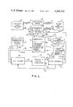
- FIG. 1 is a block diagram of a compressor fault detection and control system for a reverse cycle refrigeration system embodying the present invention.
- FIGS. 2A and 2B comprise a flow chart for the control of the apparatus shown in FIG. 1.
- the reverse cycle refrigeration system comprises an indoor heat exchange coil 10, and outdoor heat exchange coil 12, a refrigerant compression means or compressor 14, a compressor controller 15 energized from an appropriate source 17 of electrical energy, and refrigerant conduit means interconnecting the coils and compressor, the conduit means including the usual reversing valve 16 having a controller 18, an expansion means 20, and appropriate interconnecting piping 21-26.
- the system above described is representative of prior art systems such as that shown in the U.S. Pat. No. 3,170,304. As is well known, such systems function whenever the building thermostat is calling for heating or cooling to cause the compressor 14 to operate.
- the compressed hot refrigerant from the compressor 14 will be routed through the reversing valve 16 toward the indoor heat exchange coil 10 where its heat is given up to heat indoor air. Conversely, if cooling of the building is being demanded, then the hot refrigerant from the compressor is routed through the reversing valve to the outdoor heat exchange coil where the refrigerant is cooled for subsequent use indoors to cool the building.
- the compressor fault detection and control system as depicted in FIG. 1 comprises an outdoor air temperature sensing means 31 (hereinafter sometimes referred to as "TODAS") having an output 32 on which is a signal indicative of the outdoor air temperature (hereinafter sometimes referred to as "TODA").
- TODA on 32 comprises one of two inputs to a multiplexer 40 to be described in more detail below.
- the compressor fault detection and control system further comprises a compressor discharge refrigerant temperature sensing means (hereinafter sometimes referred to as "TDSCHS”) 34 having an output 35 (connected to multiplexer 40 as the second input thereof) on which is a signal indicative of the temperature of the refrigerant on the discharge side of compressor 14, said temperature hereinafter sometimes being referred to as "TDSCH” and the detection and control system further includes a room thermostat 42 (hereinafter sometimes referred to as "STAT”) which responds to the temperature of a room or space in a building or the like, the temperature of which is to be controlled by the reverse cycle refrigeration system.
- STAT room thermostat
- Room thermostat 42 is depicted as having a first output 43 connected to the control 18 for the reversing valve 16 and a second output 44 connected to a microprocessor 50 and also, through a set of normally closed contacts 46 and a connection means 45, to the controller 15 of compressor 14. Contacts 46 are contained within a subsection 47 of the microprocessor 50 and both 47 and 50 will be described in more detail below.
- a Honeywell Inc. Model T872 heating-cooling thermostat may be used for the room thermostat 42 depicted in FIG. 1, the Model T872 being of the bimetal operated mercury switch type including switch means for providing the heating-cooling control signals and also for controlling a plurality of auxiliary heating means.
- a control signal is effectively supplied on outputs 43 and 44 thereof; the control signal at 43 functioning to position via control 18 the reversing valve 16 to the proper orientation for either heating or cooling of the building and the control signal at 44 being transmitted through the normally closed contacts 46 and connection 45 to control the compressor 14 from a rest or "off" position to an operating or “on” condition.
- the control signal at 44 is also applied to the microprocessor 50 to indicate a demand for compressor 14 operation.
- Honeywell Inc. platinum film resistance type temperature sensors models C800A and C800C may be used for TODAS 31 and TDSCHS 34 respectively.
- a Westinghouse Inc. HI-RE-LI unit comprising an outdoor unit model no. HL036COW and indoor unit AG012HOK may be used for the basic heat pump unit depicted in FIG. 1; i.e., components 10, 12, 14, 15, and 16.
- Multiplexer 40 thus has applied thereto at 32 and 35 analog signals representative of TODA and TDSCH respectively.
- the function of the multiplexer 40 is to supply one or the other of the two input signals in analog form to the output 53 thereof, depending upon the nature of the control signal being applied to the multiplexer 40 via a lead 52 from the microprocessor 50; i.e., the microprocessor provides a control for the multiplexer 40 to select which of the two input signals is applied to output 53.
- Output 53 is applied as the input to a standard analog-to-digital converter 54 (hereinafter sometimes referred to as "A/O") having an output 55 connected as a second input to the microprocessor 50 and also having an input 56 for receiving controlling instructions from the microprocessor 50.
- A/O standard analog-to-digital converter
- the output from analog-to-digital convertor 54 at output 55 is a signal in digital form indicative of the analog signal applied to input 53.
- the microprocessor has a first output connection 60 which is connected to the control 18 of the reversing valve 16 so as if desired, to control the reversing valve independently of the control supplied to 18 from the room thermostat 42.
- the microprocessor 50 has a second output 62 connected to a suitable fault indicator 63 such as a warning light and/or audible alarm or the like.
- the apparatus further includes a suitable fault reset means 65 (such as a switch) having an output 66 which constitutes a third input to the microprocessor 50.
- a suitable microprocessor that may be used in the present invention as a component of the system depicted in FIG. 1 is the Intel Corporation Model 8049; a suitable representative analog-to-digital convertor for use to provide the function of block 54 in FIG. 1 is the Texas Instrument Inc. Model TL505C (see TI Bulletin DL-S 12580); and an appropriate multiplexer is the Motorola Inc. Model MC14051BP.
- FIG. 1 The detailed operation of the compressor fault detection and control system of FIG. 1 may be more specifically understood by reference to the flowcharts depicted in FIGS. 2A and 2B.
- an entry point 101 "system turns on” reflects the status of the heat pump being powered up; i.e., power 17 being applied to compressor-controller 15 and any required control system electrical energization also being supplied.
- the system flows thence via a junction 99 to a logic instruction block 102 "thermostat calls for compressor?" having a "no" response 103 causing flow back to junction 99 where the compressor waits for the STAT to call for compressor operation, and a "yes" response 104 indicating a call by the STAT for compressor 14 to operate which flows to an instruction block 105 "record time as T 1 ".
- the flow from 105 is through a junction 106 and thence to an instruction block 107 "connect TODAS to analog-to-digital converter (A/D)", the flow from which is through an instruction block 108 “measure TODA” the flow from which is to instruction block 109 “connected TDSCHS to A/D”, the flow from which is to instruction block 110 "measure TDSCH”, (which the flow from which is to a logic instruction block 115 "TDSCH is greater than TODA plus K 1 ?" having a no response 116 applied to instruction block 118 "note time as T2" and a "yes” response 119 which causes flow to an instruction block 120 "record time as T3" via a junction 121.
- Response 116 indicates that the appropriate temperature difference K 1 has not been reached to indicate that the compressor is operating.
- Response 119 indicates that this differential has been reached and that the compressor is operating correctly.
- Instruction block 120 records the starting time
- the flow from instruction block 118 is to a logic instruction block 125 "T2 minus T1 is greater than K 2 " having a "yes" response 126 and a "no" response 127.
- Yes response 126 thus represents the situation of a faulty compressor; i.e., after a predetermined or preselected period of time (T2 minus T1 is greater than K 2 ; we have found 5 minutes an appropriate value) the compressor has not functioned to raise the discharge temperature to a sufficiently high level as is proved by the functioning of logic instruction block 115.
- the yes response 126 is applied via a junction 130 to an instruction block 131 "indicate fault” (this causes actuation of indicator 63) the flow from which is to an instruction block 132 "inhibit compressor". This then is effective to cause the normally open contacts 46 (of subsection 47 of microprocessor 50) to open so as to interrupt the control of compressor controller 15 by the STAT 42, and to inhibit further compressor operation.
- the no response 127 thereof flows to a logic instruction block 144 "thermostat calls for compressor?" having a yes response 145 and a no response 146.
- a yes response at 145 will flow to junction 106 and the system will continue to recycle with the timer and temperature difference functions continuing so that time T2 will increase until eventually either the equations of instructions 115 or 125 results in a yes response at 119 or 126 respectively as aforesaid, indicating that either the compressor 14 has started properly or that it has not started properly in the allowed time K 2 .
- a means 65 e.g., a reset switch, is provided in the system to reset the entire fault detection and control system subsequent to a fault being detected and fault indicator 63 being actuated.
- a means 65 e.g., a reset switch
- logic instruction block 134 receives the flow from instruction block 132 via a junction 133
- logic instruction block 134 "has fault reset and activated?” has a no response 135 flowing back to the junction 133 and thence to block 134, indicating that reset has not been requested and that a yes response 136 flowing via 140 and 147 to junction 99 so as to restart the system.
- the flow from 120 is to instruction block 150 "record current value of TDSCH as TD", which stores the value of TDSCH at the beginning of said time interval K 3 , the flow from which is via a junction 151 thence to logic instruction block 152 "thermostat calls for compressor?" having a no response 153 connected to junction 99 indicating that the termostat is satisfied, and a yes response indicating a continuing call for compressor operation, causing flow to an instruction block 160 "connect TDSCHS to A/D” the flow from which is to instruction block 162 “measure TDSCH” the flow from which is to instruction block 162 "connect TODA to A/D", the flow from which is to instruction block 163 “measure TODA”, the flow from which is to logic instruction block 164 "TDSCH is greater than TODA plus K 5 ?”, all of which consist of measuring TDSCH and TODA and comparing their difference with a value K 5 which is the minimum difference for which the compressor is considered to be operating properly.
- a no response 166 indicating the compressor is not operating properly causes flow to junction 130 to indicate a fault and inhibit the compressor, and a yes response 165 indicating proper operation causes flow to an instruction block 170 "note time as T4 from which is to a logic instruction block 171 "T4 minus T3 equals K 3 ?"; a no response 172 therefrom, indicating that time interval K 3 has not passed, causing flow by 172 back to junction 151 to repeat the differential temperature measurement, and a yes response indicating the end of time interval K 3 causing flow by 173 to a logic instruction block 176 "TDSCH minus TD is less than K 4 ?" which compares the difference between TD, the value of TDSCH at the beginning of the time interval T3 and the present value of TDSCH with the minimum change in TDSCH over interval K 3 to indicate that compressor 14 is operating properly; a no response 178 therefrom, indicating that compressor 14 is operating properly, causing flow by 178 to junction 121 to begin a new timing interval by establishing the present time as
- the apparatus depicted in FIG. 2A is representative of the operation of the compressor fault detection and control system (through the primary control of the microprocessor 50) to determine whether or not the compressor 14 has actually started and is actually compressing the refrigerant in the system a preselected time interval after STAT 42 calls for compressor 14 operation. This time interval gives the compressor an opportunity to raise TDSCH to the level indicative of proper compressor operation.
- logic instruction block 102 has a yes response at 104 when the thermostat is calling for a compressor operation; that logic instructions 107-110 relate to the measurement of TODA and TDSCH following which logic instruction block 115 determines whether or not the refrigerant discharge temperature TDSCH is greater than the outdoor air temperature plus the constant K 1 .
- a yes response 119 from 115 is indicative of the compressor not only operating but operating in the normal fashion; i.e., compressing the refrigerant.
- the compressing of the refrigerant causes a substantial increase in the temperature of the refrigerant.
- the compressor refrigerant discharge temperature has not increased substantially after the compressor had been running for a preselected period of time, say five minutes, then this is conclusive evidence that the compressor has a fault and it should be, at least temporarily, stopped so that an inspection may be made for the source of the problem; e.g., a leak of refrigerant, etc.
- a no response 116 from 115 causes flow to logic instruction block 125 which has a yes response 126 flowing therefrom to 130 when the preselected time interval has elapsed; thus, if the discharge temperature TDSCH is not hot enough after the time interval, the yes response 126 causes the indication of a fault through the functioning of instruction block 131 causing the actuation of the fault indicator 63 of FIG. 1 and simultaneously the inhibiting of the compressor 132 which, as explained above, causes the opening of the normally closed contact 46 so as to remove control of the compressor controller 15 from STAT 42.
- the fault detection and control system also functions to monitor the operation of the heat pump system during a compressor run; i.e., following the initial determination (described above) that the compressor not only is operating but is actually compressing.
- the yes response 119 from logic instruction block 115 flows to junction 121.
- the apparatus depicted in FIG. 2B generally is representive of the function of periodically measuring the discharge temperature, i.e., at preselected time intervals, and then making comparisons of such successive temperature measurements and inhibiting the further operation of the compressor if, at the end of any of such time intervals, it is found that the most recent discharge temperature is less than, or colder than, the preceding discharge temperature measurement by more than a preselected amount.
- the yes response 119 causes the initiation of the operation 120 and effectively starts the running of a discharge timer; further, the function of instruction block 150 is to record the beginning value or magnitude of the refrigerant discharge temperature TDSCH, this particular value being identified in block 150 by the abbreviation "TD". Thereafter, there is a test to confirm that the thermostat is still calling for compressor action (block 152) a yes response 154 therefrom then enabling the operations called out in instruction blocks 160-163 inclusive; i.e., the measurements of TDSCH and TODA.
- TDSCH minus TD is less than the constant K 4 , then this is a confirmation that the refrigerant compression function has for some reason stopped after initially being satisfactory and that the system should be shut down. Accordingly, the yes response causes flow via 177 to cause a fault indication 131/63 and the inhibiting of the compressor operation 132 by the opening of normally closed contacts 46. If, at 176, TDSCH minus TD is greater than K 4 , then the no response 178 causes flow back to junction 121 so that the subsystem recycles, it being understood that this periodic checking of the discharge temperature is a continuous process; i.e., goes on as long as the thermostat is calling for compressor action.
- an Intel Model 8049 microprocessor may be used to practice the subject invention; as an assistance, reference may be made to "INTEL® MCS-48TM Family of Single Chip Microcomputers--User's Manual", a 1978 copyrighted manual of the Intel Corporation, Santa Clara, California 95051.
- Appendix A hereto and forming a part hereof comprises a table of machine readable instruction for controlling the aforesaid Intel Model 8049 microprocessor for use in the present invention.
Abstract
A compressor fault detection and control system for a reverse cycle refrigeration system for detecting faulty compressor operation and for controlling the system in response to the detection of a fault by inhibiting the compressor and for providing a fault indication, the control system comprising a controller means receiving inputs indicative of the outdoor air temperature, the temperature of the compressor discharge refrigerant, and an output indicative of a demand from a building temperature sensing means for heating or cooling of the building. The controller means also includes timing means and means for comparing the value of the compressor discharge temperature and the value of the outdoor air temperature. Further, the controller means has an operative connection to control means for controlling the operation of the compressor and functioning, after the compressor has been operating for a preselected time interval, to inhibit any further operation of the compressor means unless the value of the compressor discharge temperature is greater than the value of the outdoor air temperature plus a preselected constant value.
Description
One significant problem with heat pumps is a possible system malfunction whereby the room thermostat in the room to be heated and/or cooled by the heat pump commands compressor operation so as to either heat or cool the space but the compressor either does not operate or, in some cases, cycles on and off. Another system malfunction is where the compressor is energized and running but is not compressing the refrigerant; this is exemplified by the compressor valve failures and/or the loss of refrigerant. There are no obvious indications of these faults to a person near the thermostat because the compressor is at a location remote from that of the thermostat. This, in turn, with many systems, can mean (when the thermostat is calling for heating of the building) that auxiliary electric resistance heating is automatically used to heat the building; i.e., a backup heating system; however, this usually results in a much higher cost of heating. Accordingly, various prior art schemes have been devised for attempting to detect whether or not the compressor is running, or is running without refrigerant in the system, but all of these prior art arrangements have one or more shortcomings. For example, one prior scheme is to use the pressure of the refrigerant at the discharge side of the compressor; however, this does not provide a reliable enough signal. Also, it has been proposed that the value or magnitude of the electric current and/or electric voltage energizing the motor driving the compressor be monitored; however, these schemes only indicate that the motor is being powered and do not confirm that the compressor is actually pumping refrigerant.
An object of the present invention is to provide a new and significantly improved compressor fault detection system for a reverse cycle refrigeration system.
The present invention is a compressor fault detection and control system for a reverse cycle refrigeration system comprising the usual refrigeration compression means, indoor coil, outdoor coil, refrigerant conduit means connecting the compression means and the coils, and refrigerant compression control means. In particular, the compression fault detection and control system comprises outdoor air temperature sensing means having an output indicative of outdoor air temperature, compressor discharge sensing means having an output indicative of the temperature of the refrigerant discharged from the refrigerant compression means, building temperature sensing means having an output indicative of a demand for heating or cooling of the building, and a special controller means. The special controller means has operative connections to the above recited temperature sensing means so as to receive the outputs thereof. The controller has a timing function which is initiated upon the starting or commencement of operation of the compressor. The controller means further includes a circuit connection-disconnection means for selectively interconnecting the building temperature sensing means to the refrigerant compression control means, the building temperature sensing means output normally being connected to the refrigerant compression control means so as to cause the compressor to run or operate whenever there is a demand for heating or cooling of the building. The controller means further is characterized by being adapted to inhibit the operation of the compressor means if, after a predetermined time interval as measured by the timing means, the value of the discharge temperature is less than the value of the outdoor air temperature plus a preselected constant K1.
The invention may further include a means of monitoring the operation of the compressor after the above described system has already established that the compressor is running in a satisfactory manner. One of the heat pump problems that the present invention solves is where the compressor is cycling on and off over a period of time when the room thermostat is demanding continuous operation of the compressor being caused by some system malfunction; e.g., the high pressure limit switch interrupting the power to the compressor. The effect of the interrupted compressor operation is to cause some fluctuation in the temperature of the discharge refrigerant. Accordingly, our invention, as indicated, provides a further means of monitoring a compressor; this additional system includes a means for measuring the discharge temperature at preselected intervals of time and comparing successive temperature measurements and inhibiting the further operation of the compressor if, at the end of each interval, it is found that the most recent temperature measurement is less than the preceding temperature measurement by more than a preselected variance.
FIG. 1 is a block diagram of a compressor fault detection and control system for a reverse cycle refrigeration system embodying the present invention; and
FIGS. 2A and 2B comprise a flow chart for the control of the apparatus shown in FIG. 1.
Referring to FIG. 1, the reverse cycle refrigeration system comprises an indoor heat exchange coil 10, and outdoor heat exchange coil 12, a refrigerant compression means or compressor 14, a compressor controller 15 energized from an appropriate source 17 of electrical energy, and refrigerant conduit means interconnecting the coils and compressor, the conduit means including the usual reversing valve 16 having a controller 18, an expansion means 20, and appropriate interconnecting piping 21-26. The system above described is representative of prior art systems such as that shown in the U.S. Pat. No. 3,170,304. As is well known, such systems function whenever the building thermostat is calling for heating or cooling to cause the compressor 14 to operate. If heating is being demanded, then the compressed hot refrigerant from the compressor 14 will be routed through the reversing valve 16 toward the indoor heat exchange coil 10 where its heat is given up to heat indoor air. Conversely, if cooling of the building is being demanded, then the hot refrigerant from the compressor is routed through the reversing valve to the outdoor heat exchange coil where the refrigerant is cooled for subsequent use indoors to cool the building.
The compressor fault detection and control system as depicted in FIG. 1 comprises an outdoor air temperature sensing means 31 (hereinafter sometimes referred to as "TODAS") having an output 32 on which is a signal indicative of the outdoor air temperature (hereinafter sometimes referred to as "TODA"). TODA on 32 comprises one of two inputs to a multiplexer 40 to be described in more detail below. The compressor fault detection and control system further comprises a compressor discharge refrigerant temperature sensing means (hereinafter sometimes referred to as "TDSCHS") 34 having an output 35 (connected to multiplexer 40 as the second input thereof) on which is a signal indicative of the temperature of the refrigerant on the discharge side of compressor 14, said temperature hereinafter sometimes being referred to as "TDSCH" and the detection and control system further includes a room thermostat 42 (hereinafter sometimes referred to as "STAT") which responds to the temperature of a room or space in a building or the like, the temperature of which is to be controlled by the reverse cycle refrigeration system. Room thermostat 42 is depicted as having a first output 43 connected to the control 18 for the reversing valve 16 and a second output 44 connected to a microprocessor 50 and also, through a set of normally closed contacts 46 and a connection means 45, to the controller 15 of compressor 14. Contacts 46 are contained within a subsection 47 of the microprocessor 50 and both 47 and 50 will be described in more detail below.
A Honeywell Inc. Model T872 heating-cooling thermostat may be used for the room thermostat 42 depicted in FIG. 1, the Model T872 being of the bimetal operated mercury switch type including switch means for providing the heating-cooling control signals and also for controlling a plurality of auxiliary heating means. As will be understood, whenever STAT 42 calls for either heating or cooling of the controlled space, then a control signal is effectively supplied on outputs 43 and 44 thereof; the control signal at 43 functioning to position via control 18 the reversing valve 16 to the proper orientation for either heating or cooling of the building and the control signal at 44 being transmitted through the normally closed contacts 46 and connection 45 to control the compressor 14 from a rest or "off" position to an operating or "on" condition. The control signal at 44 is also applied to the microprocessor 50 to indicate a demand for compressor 14 operation.
Further, Honeywell Inc. platinum film resistance type temperature sensors models C800A and C800C may be used for TODAS 31 and TDSCHS 34 respectively. Also, a Westinghouse Inc. HI-RE-LI unit comprising an outdoor unit model no. HL036COW and indoor unit AG012HOK may be used for the basic heat pump unit depicted in FIG. 1; i.e., components 10, 12, 14, 15, and 16.
The microprocessor has a first output connection 60 which is connected to the control 18 of the reversing valve 16 so as if desired, to control the reversing valve independently of the control supplied to 18 from the room thermostat 42. The microprocessor 50 has a second output 62 connected to a suitable fault indicator 63 such as a warning light and/or audible alarm or the like. The apparatus further includes a suitable fault reset means 65 (such as a switch) having an output 66 which constitutes a third input to the microprocessor 50.
A suitable microprocessor that may be used in the present invention as a component of the system depicted in FIG. 1 is the Intel Corporation Model 8049; a suitable representative analog-to-digital convertor for use to provide the function of block 54 in FIG. 1 is the Texas Instrument Inc. Model TL505C (see TI Bulletin DL-S 12580); and an appropriate multiplexer is the Motorola Inc. Model MC14051BP.
It will be understood by those skilled in the art that the functional interconnections depicted in FIG. 1 are representative of one or more electrical wires or pipes, as the case may be, as dictated by the specific equipment used.
The detailed operation of the compressor fault detection and control system of FIG. 1 may be more specifically understood by reference to the flowcharts depicted in FIGS. 2A and 2B.
Referring to FIG. 2A, an entry point 101 "system turns on" reflects the status of the heat pump being powered up; i.e., power 17 being applied to compressor-controller 15 and any required control system electrical energization also being supplied. The system flows thence via a junction 99 to a logic instruction block 102 "thermostat calls for compressor?" having a "no" response 103 causing flow back to junction 99 where the compressor waits for the STAT to call for compressor operation, and a "yes" response 104 indicating a call by the STAT for compressor 14 to operate which flows to an instruction block 105 "record time as T1 ". This initiates or starts a timer within microprocessor 50 to enable an elapsed time measurement (T2-T1) operation as will be discussed below. The flow from 105 is through a junction 106 and thence to an instruction block 107 "connect TODAS to analog-to-digital converter (A/D)", the flow from which is through an instruction block 108 "measure TODA" the flow from which is to instruction block 109 "connected TDSCHS to A/D", the flow from which is to instruction block 110 "measure TDSCH", (which the flow from which is to a logic instruction block 115 "TDSCH is greater than TODA plus K1 ?" having a no response 116 applied to instruction block 118 "note time as T2" and a "yes" response 119 which causes flow to an instruction block 120 "record time as T3" via a junction 121. Response 116 indicates that the appropriate temperature difference K1 has not been reached to indicate that the compressor is operating. Response 119 indicates that this differential has been reached and that the compressor is operating correctly. Instruction block 120 records the starting time T3 of a fixed interval K3.
The flow from instruction block 118 is to a logic instruction block 125 "T2 minus T1 is greater than K2 " having a "yes" response 126 and a "no" response 127. Yes response 126 thus represents the situation of a faulty compressor; i.e., after a predetermined or preselected period of time (T2 minus T1 is greater than K2 ; we have found 5 minutes an appropriate value) the compressor has not functioned to raise the discharge temperature to a sufficiently high level as is proved by the functioning of logic instruction block 115. Accordingly, the yes response 126 is applied via a junction 130 to an instruction block 131 "indicate fault" (this causes actuation of indicator 63) the flow from which is to an instruction block 132 "inhibit compressor". This then is effective to cause the normally open contacts 46 (of subsection 47 of microprocessor 50) to open so as to interrupt the control of compressor controller 15 by the STAT 42, and to inhibit further compressor operation.
Note that our system does not rely only upon the magnitude of TDSCH; we recognize that, to some extent, TDSCH is affected by the magnitude of TODA; hence, logic instruction block has a "fault" response if TDSCH is not greater than TODA plus the preselected constant K1, the value of which is selected according to the specifics of the actual equipment used.
Referring again to logic instruction 125, the no response 127 thereof flows to a logic instruction block 144 "thermostat calls for compressor?" having a yes response 145 and a no response 146. Thus, if STAT 42 continues to call for compressor action then a yes response at 145 will flow to junction 106 and the system will continue to recycle with the timer and temperature difference functions continuing so that time T2 will increase until eventually either the equations of instructions 115 or 125 results in a yes response at 119 or 126 respectively as aforesaid, indicating that either the compressor 14 has started properly or that it has not started properly in the allowed time K2.
If STAT 42 is no longer calling for compressor action, then the no response 146 of block 144 flows to a junction 140 and thence through a connection 147 to the junction 99 and thence, as in the beginning, to logic instruction block 102.
As indicated, a means 65, e.g., a reset switch, is provided in the system to reset the entire fault detection and control system subsequent to a fault being detected and fault indicator 63 being actuated. In FIG. 2A this is reflected by logic instruction block 134 being receives the flow from instruction block 132 via a junction 133, logic instruction block 134 "has fault reset and activated?" has a no response 135 flowing back to the junction 133 and thence to block 134, indicating that reset has not been requested and that a yes response 136 flowing via 140 and 147 to junction 99 so as to restart the system.
Referring to logic instruction block 115 it was noted above that the yes response 119 thereof, indicating that the compressor is operating properly, causes flow to junction 121 and thence to instruction block 120 "record time as T3", which notes the beginning of a time interval of length K3. The flow from 120 is to instruction block 150 "record current value of TDSCH as TD", which stores the value of TDSCH at the beginning of said time interval K3, the flow from which is via a junction 151 thence to logic instruction block 152 "thermostat calls for compressor?" having a no response 153 connected to junction 99 indicating that the termostat is satisfied, and a yes response indicating a continuing call for compressor operation, causing flow to an instruction block 160 "connect TDSCHS to A/D" the flow from which is to instruction block 162 "measure TDSCH" the flow from which is to instruction block 162 "connect TODA to A/D", the flow from which is to instruction block 163 "measure TODA", the flow from which is to logic instruction block 164 "TDSCH is greater than TODA plus K5 ?", all of which consist of measuring TDSCH and TODA and comparing their difference with a value K5 which is the minimum difference for which the compressor is considered to be operating properly. A no response 166 indicating the compressor is not operating properly causes flow to junction 130 to indicate a fault and inhibit the compressor, and a yes response 165 indicating proper operation causes flow to an instruction block 170 "note time as T4 from which is to a logic instruction block 171 "T4 minus T3 equals K3 ?"; a no response 172 therefrom, indicating that time interval K3 has not passed, causing flow by 172 back to junction 151 to repeat the differential temperature measurement, and a yes response indicating the end of time interval K3 causing flow by 173 to a logic instruction block 176 "TDSCH minus TD is less than K4 ?" which compares the difference between TD, the value of TDSCH at the beginning of the time interval T3 and the present value of TDSCH with the minimum change in TDSCH over interval K3 to indicate that compressor 14 is operating properly; a no response 178 therefrom, indicating that compressor 14 is operating properly, causing flow by 178 to junction 121 to begin a new timing interval by establishing the present time as a new value for the start of the interval T3, and a yes response 177 indicating that compressor 14 is not operating properly, therefrom causing flow by 177 back to junction 130 to indicate a fault condition.
To summarize, it is seen that the apparatus depicted in FIG. 2A is representative of the operation of the compressor fault detection and control system (through the primary control of the microprocessor 50) to determine whether or not the compressor 14 has actually started and is actually compressing the refrigerant in the system a preselected time interval after STAT 42 calls for compressor 14 operation. This time interval gives the compressor an opportunity to raise TDSCH to the level indicative of proper compressor operation. It was noted logic instruction block 102 has a yes response at 104 when the thermostat is calling for a compressor operation; that logic instructions 107-110 relate to the measurement of TODA and TDSCH following which logic instruction block 115 determines whether or not the refrigerant discharge temperature TDSCH is greater than the outdoor air temperature plus the constant K1. A yes response 119 from 115 is indicative of the compressor not only operating but operating in the normal fashion; i.e., compressing the refrigerant. To explain further, when the compressor is functioning in the normal mode, the compressing of the refrigerant causes a substantial increase in the temperature of the refrigerant. Thus, if the compressor refrigerant discharge temperature has not increased substantially after the compressor had been running for a preselected period of time, say five minutes, then this is conclusive evidence that the compressor has a fault and it should be, at least temporarily, stopped so that an inspection may be made for the source of the problem; e.g., a leak of refrigerant, etc. Thus, a no response 116 from 115 causes flow to logic instruction block 125 which has a yes response 126 flowing therefrom to 130 when the preselected time interval has elapsed; thus, if the discharge temperature TDSCH is not hot enough after the time interval, the yes response 126 causes the indication of a fault through the functioning of instruction block 131 causing the actuation of the fault indicator 63 of FIG. 1 and simultaneously the inhibiting of the compressor 132 which, as explained above, causes the opening of the normally closed contact 46 so as to remove control of the compressor controller 15 from STAT 42.
The fault detection and control system also functions to monitor the operation of the heat pump system during a compressor run; i.e., following the initial determination (described above) that the compressor not only is operating but is actually compressing. Thus, the yes response 119 from logic instruction block 115 flows to junction 121. The apparatus depicted in FIG. 2B generally is representive of the function of periodically measuring the discharge temperature, i.e., at preselected time intervals, and then making comparisons of such successive temperature measurements and inhibiting the further operation of the compressor if, at the end of any of such time intervals, it is found that the most recent discharge temperature is less than, or colder than, the preceding discharge temperature measurement by more than a preselected amount.
Thus, the yes response 119 causes the initiation of the operation 120 and effectively starts the running of a discharge timer; further, the function of instruction block 150 is to record the beginning value or magnitude of the refrigerant discharge temperature TDSCH, this particular value being identified in block 150 by the abbreviation "TD". Thereafter, there is a test to confirm that the thermostat is still calling for compressor action (block 152) a yes response 154 therefrom then enabling the operations called out in instruction blocks 160-163 inclusive; i.e., the measurements of TDSCH and TODA. Next, a check is made to confirm that the compressor is still running; this is accomplished by the function by logic instruction block 164 (note that once again TDSCH is required to be greater than TODA plus a constant K5); if this block provides a no response 166, the compressor operation is inhibited and the fault indicator 63 actuated; a yes response 165 signifies that the compressor is indeed running; and accordingly, the next instruction block 170 is executed so as to perform the indicated time measurement function following which the logic instruction block 171 compares T4 and T3; if the elapsed time T4-T3 is sufficiently large, i.e., equal to the constant K3, then this signifies that sufficient time has elapsed since the beginning time T3; and accordingly, a yes response causes flow via 173 to permit the logic instruction block 176 to compare the beginning discharge temperature "TD" with the current or present discharge temperature TDSCH. As indicated in FIG. 2B at 176, if TDSCH minus TD is less than the constant K4, then this is a confirmation that the refrigerant compression function has for some reason stopped after initially being satisfactory and that the system should be shut down. Accordingly, the yes response causes flow via 177 to cause a fault indication 131/63 and the inhibiting of the compressor operation 132 by the opening of normally closed contacts 46. If, at 176, TDSCH minus TD is greater than K4, then the no response 178 causes flow back to junction 121 so that the subsystem recycles, it being understood that this periodic checking of the discharge temperature is a continuous process; i.e., goes on as long as the thermostat is calling for compressor action.
As indicated above, an Intel Model 8049 microprocessor may be used to practice the subject invention; as an assistance, reference may be made to "INTEL® MCS-48™ Family of Single Chip Microcomputers--User's Manual", a 1978 copyrighted manual of the Intel Corporation, Santa Clara, California 95051. As a further assistance, Appendix A hereto and forming a part hereof, comprises a table of machine readable instruction for controlling the aforesaid Intel Model 8049 microprocessor for use in the present invention.
It will also be understood by those skilled in the art that the functional interconnections depicted in FIG. 1 are representative of one or more electrical wires or pipes, as the case may be, as dictated by the specific equipment used.
While we have described a preferred embodiment of our invention, it will be understood that the invention is limited only by the scope of the following claims:
Claims (8)
1. A compressor fault detection and control system (hereinafter "fault detection system") for a reverse cycle refrigeration system (hereinafter "system") for heating and cooling a building wherein said system comprises refrigerant compression means, refrigerant compression control means, an indoor coil, an outdoor coil, and refrigerant conduit means connecting said compression means and said coils, said fault detection system comprising:
outdoor air temperature sensing means (hereinafter "TODAS") having an output indicative of outdoor air temperature (hereinafter "TODA");
compressor discharge temperature sensing means (hereinafter "TDSCHS") having an output indicative of the temperature (hereinafter "TDSCH") of the refrigerant discharged from said refrigerant compression means; and
building temperature sensing means (hereinafter "STAT") having an output indicative of a demand for heating or cooling of the building; and
controller means having operative connections to said TODAS, TDSCHS, and STAT so as to receive the outputs thereof, said controller means including circuit connect-disconnect means selectively interconnecting said STAT output to said refrigerant compression control means whereby when said STAT output is connected thereto said compression means is enabled to operate and when said STAT output is disconnected therefrom said compression means is inhibited from operating, said controller means also including timing means and means for comparing the value of TDSCH and the value of TODA plus a preselected constant K1, and said controller further being characterized by being adapted to inhibit said compression means from operating if, after a preselected time interval as measured by said timing means, the value of TDSCH is less than the value of TODA plus said predetermined constant.
2. A compressor fault detection and control system (hereinafter "fault detection system") for a reverse cycle refrigeration system (hereinafter "system") for heating and cooling a building wherein said system comprises refrigerant compression means, refrigerant compression control means, an indoor coil, an outdoor coil, and refrigerant conduit means connecting said compression means and said coils, said fault detection system comprising:
outdoor air temperature sensing means (hereinafter "TODAS") having an output indicative of outdoor air temperature (hereinafter "TODA");
compressor discharge temperature sensing means (hereinafter "TDSCHS") having an output indicative of the temperature (hereinafter "TDSCH") of the refrigerant discharged from said refrigerant compression means; and
controller means having operative connections to said TODAS, TDSCHS, and to said refrigerant compression control means whereby said compression means is enabled to operate or is inhibited from operating, said controller means also including timing means and means for comparing the value of TDSCH and the value of TODA plus a preselected constant K1, and said controller further being characterized by being adapted to inhibit said compression means from operating if, after a preselected time interval as measured by said timing means, the value of TDSCH is less than the value of TODA plus K1.
3. Apparatus of claim 2 further characterized by said controller means including means for performing comparisons of the value of TDSCH at predetermined intervals of time and being effective to inhibit the operation of said compression means if, at the completion of one of said time intervals, the then current value of TDSCH minus the value of TDSCH at the beginning of said time interval is less than a predetermined amount.
4. Apparatus of claim 2 further characterized by said controller means including means for performing comparisons of the value of TDSCH at predetermined intervals of time and for inhibiting the operation of said compression means if, upon the completion of one of said time intervals, the then current value of TDSCH differs from the value of TDSCH at the beginning of the time interval by an amount greater than a preselected amount.
5. A compressor fault detection and control system (hereinafter "fault detection system") for a reverse cycle refrigeration system (hereinafter "system") for heating and cooling a building wherein said system comprises refrigerant compression means, refrigerant compression control means, an indoor coil, an outdoor coil, and refrigerant conduit means connecting said compression means and said coils, said fault detection system comprising:
compressor discharge temperature sensing means (hereinafter "TDSCHS") having an output indicative of the temperature (hereinafter "TDSCH") of the refrigerant discharged from said refrigerant compression means; and
controller means having an operative connection to said TDSCHS, to receive the TDSCH output thereof, said controller means including means selectively controlling said refrigerant compression control means whereby said compression means is either enabled to operate or is inhibited from operating, said controller means also including timing means and means for performing comparisons of the value of TDSCH at predetermined intervals of time and for inhibiting the operation of said compression means if, upon the completion of one of said time intervals, the then current value of TDSCH differs from the value of TDSCH at the beginning of the time interval by an amount greater than a preselected amount.
6. Apparatus of claim 4 further characterized by said controller means including further means for comparing, on a substantially continuous basis, the values of TDSCH and TODA and for inhibiting the operation of said compression means if the value of TDSCH is less than the value of TODA plus a predetermined constant.
7. Apparatus of claim 3 further characterized by said controller means including further means for comparing, on a substantially continuous basis, the values of TDSCH and TODA and for inhibiting the operation of said compression means if the value of TDSCH is less than the value of TODA plus a predetermined constant.
8. Apparatus of claim 1 further characterized by the inhibiting of said compression means from operating being affected by said controller means operating said connect-disconnect means to disconnect said STAT output from said refrigerant compression control means.
Priority Applications (3)
| Application Number | Priority Date | Filing Date | Title |
|---|---|---|---|
| US05/954,266 US4246763A (en) | 1978-10-24 | 1978-10-24 | Heat pump system compressor fault detector |
| CA335,491A CA1097934A (en) | 1978-10-24 | 1979-09-12 | Heat pump system compressor fault detector |
| JP13652479A JPS5556560A (en) | 1978-10-24 | 1979-10-24 | Compressor wrong operation detecting controller |
Applications Claiming Priority (1)
| Application Number | Priority Date | Filing Date | Title |
|---|---|---|---|
| US05/954,266 US4246763A (en) | 1978-10-24 | 1978-10-24 | Heat pump system compressor fault detector |
Publications (1)
| Publication Number | Publication Date |
|---|---|
| US4246763A true US4246763A (en) | 1981-01-27 |
Family
ID=25495186
Family Applications (1)
| Application Number | Title | Priority Date | Filing Date |
|---|---|---|---|
| US05/954,266 Expired - Lifetime US4246763A (en) | 1978-10-24 | 1978-10-24 | Heat pump system compressor fault detector |
Country Status (3)
| Country | Link |
|---|---|
| US (1) | US4246763A (en) |
| JP (1) | JPS5556560A (en) |
| CA (1) | CA1097934A (en) |
Cited By (36)
| Publication number | Priority date | Publication date | Assignee | Title |
|---|---|---|---|---|
| US4301660A (en) * | 1980-02-11 | 1981-11-24 | Honeywell Inc. | Heat pump system compressor fault detector |
| US4376510A (en) * | 1981-05-06 | 1983-03-15 | Allard Wayne H | Warning device and method for a heating system |
| US4574871A (en) * | 1984-05-07 | 1986-03-11 | Parkinson David W | Heat pump monitor apparatus for fault detection in a heat pump system |
| US4698978A (en) * | 1986-08-26 | 1987-10-13 | Uhr Corporation | Welded contact safety technique |
| US5042264A (en) * | 1990-09-21 | 1991-08-27 | Carrier Corporation | Method for detecting and correcting reversing valve failures in heat pump systems having a variable speed compressor |
| US5379606A (en) * | 1992-05-11 | 1995-01-10 | Sanyo Electric Co., Ltd. | Control device for an air conditioner |
| US5533352A (en) * | 1994-06-14 | 1996-07-09 | Copeland Corporation | Forced air heat exchanging system with variable fan speed control |
| US5867997A (en) * | 1997-06-27 | 1999-02-09 | Samsung Electronics Co., Ltd. | Heating control apparatus of air conditioner and method thereof |
| US20030037555A1 (en) * | 2000-03-14 | 2003-02-27 | Street Norman E. | Distributed intelligence control for commercial refrigeration |
| US20040016253A1 (en) * | 2000-03-14 | 2004-01-29 | Hussmann Corporation | Refrigeration system and method of operating the same |
| US20040016244A1 (en) * | 2000-03-14 | 2004-01-29 | Hussmann Corporation | Refrigeration system and method of configuring the same |
| US20040016251A1 (en) * | 2000-03-14 | 2004-01-29 | Hussmann Corporation | Refrigeration system and method of operating the same |
| US20040016241A1 (en) * | 2000-03-14 | 2004-01-29 | Hussmann Corporation | Refrigeration system and method of operating the same |
| US20040024495A1 (en) * | 2000-03-14 | 2004-02-05 | Hussmann Corporation | Communication network and method of communicating data on the same |
| US20040093879A1 (en) * | 2000-03-14 | 2004-05-20 | Hussmann Corporation | Distributed intelligence control for commercial refrigeration |
| US20050150650A1 (en) * | 2004-01-12 | 2005-07-14 | American Standard International, Inc. | Heat pump control system and method of operating to provide automatic backup heating modes |
| US20050235663A1 (en) * | 2004-04-27 | 2005-10-27 | Pham Hung M | Compressor diagnostic and protection system and method |
| US20080209925A1 (en) * | 2006-07-19 | 2008-09-04 | Pham Hung M | Protection and diagnostic module for a refrigeration system |
| US20090071175A1 (en) * | 2007-09-19 | 2009-03-19 | Emerson Climate Technologies, Inc. | Refrigeration monitoring system and method |
| US20100111709A1 (en) * | 2003-12-30 | 2010-05-06 | Emerson Climate Technologies, Inc. | Compressor protection and diagnostic system |
| US20110112814A1 (en) * | 2009-11-11 | 2011-05-12 | Emerson Retail Services, Inc. | Refrigerant leak detection system and method |
| US8160827B2 (en) | 2007-11-02 | 2012-04-17 | Emerson Climate Technologies, Inc. | Compressor sensor module |
| US20120279241A1 (en) * | 2011-05-05 | 2012-11-08 | Ruiz Randy T | Heat pump control |
| US8964338B2 (en) | 2012-01-11 | 2015-02-24 | Emerson Climate Technologies, Inc. | System and method for compressor motor protection |
| US8974573B2 (en) | 2004-08-11 | 2015-03-10 | Emerson Climate Technologies, Inc. | Method and apparatus for monitoring a refrigeration-cycle system |
| US9140728B2 (en) | 2007-11-02 | 2015-09-22 | Emerson Climate Technologies, Inc. | Compressor sensor module |
| US9285802B2 (en) | 2011-02-28 | 2016-03-15 | Emerson Electric Co. | Residential solutions HVAC monitoring and diagnosis |
| US9310094B2 (en) | 2007-07-30 | 2016-04-12 | Emerson Climate Technologies, Inc. | Portable method and apparatus for monitoring refrigerant-cycle systems |
| US9310439B2 (en) | 2012-09-25 | 2016-04-12 | Emerson Climate Technologies, Inc. | Compressor having a control and diagnostic module |
| US9480177B2 (en) | 2012-07-27 | 2016-10-25 | Emerson Climate Technologies, Inc. | Compressor protection module |
| US9551504B2 (en) | 2013-03-15 | 2017-01-24 | Emerson Electric Co. | HVAC system remote monitoring and diagnosis |
| US9638436B2 (en) | 2013-03-15 | 2017-05-02 | Emerson Electric Co. | HVAC system remote monitoring and diagnosis |
| US9765979B2 (en) | 2013-04-05 | 2017-09-19 | Emerson Climate Technologies, Inc. | Heat-pump system with refrigerant charge diagnostics |
| US9823632B2 (en) | 2006-09-07 | 2017-11-21 | Emerson Climate Technologies, Inc. | Compressor data module |
| US10041713B1 (en) | 1999-08-20 | 2018-08-07 | Hudson Technologies, Inc. | Method and apparatus for measuring and improving efficiency in refrigeration systems |
| US10488090B2 (en) | 2013-03-15 | 2019-11-26 | Emerson Climate Technologies, Inc. | System for refrigerant charge verification |
Citations (4)
| Publication number | Priority date | Publication date | Assignee | Title |
|---|---|---|---|---|
| US2826044A (en) * | 1956-02-08 | 1958-03-11 | Guy J Reer | Alarm mechanism for refrigeration systems |
| US3170304A (en) * | 1963-09-26 | 1965-02-23 | Carrier Corp | Refrigeration system control |
| US3702064A (en) * | 1971-08-05 | 1972-11-07 | Gen Motors Corp | Air conditioning pump shutoff |
| US4038061A (en) * | 1975-12-29 | 1977-07-26 | Heil-Quaker Corporation | Air conditioner control |
-
1978
- 1978-10-24 US US05/954,266 patent/US4246763A/en not_active Expired - Lifetime
-
1979
- 1979-09-12 CA CA335,491A patent/CA1097934A/en not_active Expired
- 1979-10-24 JP JP13652479A patent/JPS5556560A/en active Pending
Patent Citations (4)
| Publication number | Priority date | Publication date | Assignee | Title |
|---|---|---|---|---|
| US2826044A (en) * | 1956-02-08 | 1958-03-11 | Guy J Reer | Alarm mechanism for refrigeration systems |
| US3170304A (en) * | 1963-09-26 | 1965-02-23 | Carrier Corp | Refrigeration system control |
| US3702064A (en) * | 1971-08-05 | 1972-11-07 | Gen Motors Corp | Air conditioning pump shutoff |
| US4038061A (en) * | 1975-12-29 | 1977-07-26 | Heil-Quaker Corporation | Air conditioner control |
Cited By (88)
| Publication number | Priority date | Publication date | Assignee | Title |
|---|---|---|---|---|
| US4301660A (en) * | 1980-02-11 | 1981-11-24 | Honeywell Inc. | Heat pump system compressor fault detector |
| US4376510A (en) * | 1981-05-06 | 1983-03-15 | Allard Wayne H | Warning device and method for a heating system |
| US4574871A (en) * | 1984-05-07 | 1986-03-11 | Parkinson David W | Heat pump monitor apparatus for fault detection in a heat pump system |
| US4698978A (en) * | 1986-08-26 | 1987-10-13 | Uhr Corporation | Welded contact safety technique |
| WO1988001716A1 (en) * | 1986-08-26 | 1988-03-10 | Uhr Corporation | Welded contact safety technique |
| US5042264A (en) * | 1990-09-21 | 1991-08-27 | Carrier Corporation | Method for detecting and correcting reversing valve failures in heat pump systems having a variable speed compressor |
| US5379606A (en) * | 1992-05-11 | 1995-01-10 | Sanyo Electric Co., Ltd. | Control device for an air conditioner |
| US5533352A (en) * | 1994-06-14 | 1996-07-09 | Copeland Corporation | Forced air heat exchanging system with variable fan speed control |
| US5867997A (en) * | 1997-06-27 | 1999-02-09 | Samsung Electronics Co., Ltd. | Heating control apparatus of air conditioner and method thereof |
| US10041713B1 (en) | 1999-08-20 | 2018-08-07 | Hudson Technologies, Inc. | Method and apparatus for measuring and improving efficiency in refrigeration systems |
| US20060117773A1 (en) * | 2000-03-14 | 2006-06-08 | Hussmann Corporation | Refrigeration system and method of operating the same |
| US7270278B2 (en) | 2000-03-14 | 2007-09-18 | Hussmann Corporation | Distributed intelligence control for commercial refrigeration |
| US20040016251A1 (en) * | 2000-03-14 | 2004-01-29 | Hussmann Corporation | Refrigeration system and method of operating the same |
| US20040016241A1 (en) * | 2000-03-14 | 2004-01-29 | Hussmann Corporation | Refrigeration system and method of operating the same |
| US20040024495A1 (en) * | 2000-03-14 | 2004-02-05 | Hussmann Corporation | Communication network and method of communicating data on the same |
| US20040093879A1 (en) * | 2000-03-14 | 2004-05-20 | Hussmann Corporation | Distributed intelligence control for commercial refrigeration |
| US7617691B2 (en) | 2000-03-14 | 2009-11-17 | Hussmann Corporation | Refrigeration system and method of operating the same |
| US20040016253A1 (en) * | 2000-03-14 | 2004-01-29 | Hussmann Corporation | Refrigeration system and method of operating the same |
| US20050252220A1 (en) * | 2000-03-14 | 2005-11-17 | Hussmann Corporation | Refrigeration system and method of operating the same |
| US20050262856A1 (en) * | 2000-03-14 | 2005-12-01 | Hussmann Corporation | Refrigeration system and method of operating the same |
| US6973794B2 (en) * | 2000-03-14 | 2005-12-13 | Hussmann Corporation | Refrigeration system and method of operating the same |
| US6999996B2 (en) | 2000-03-14 | 2006-02-14 | Hussmann Corporation | Communication network and method of communicating data on the same |
| US7000422B2 (en) | 2000-03-14 | 2006-02-21 | Hussmann Corporation | Refrigeration system and method of configuring the same |
| US7047753B2 (en) | 2000-03-14 | 2006-05-23 | Hussmann Corporation | Refrigeration system and method of operating the same |
| US20030037555A1 (en) * | 2000-03-14 | 2003-02-27 | Street Norman E. | Distributed intelligence control for commercial refrigeration |
| US7228691B2 (en) | 2000-03-14 | 2007-06-12 | Hussmann Corporation | Refrigeration system and method of operating the same |
| US20040016244A1 (en) * | 2000-03-14 | 2004-01-29 | Hussmann Corporation | Refrigeration system and method of configuring the same |
| US7320225B2 (en) | 2000-03-14 | 2008-01-22 | Hussmann Corporation | Refrigeration system and method of operating the same |
| US7421850B2 (en) * | 2000-03-14 | 2008-09-09 | Hussman Corporation | Refrigeration system and method of operating the same |
| US8850838B2 (en) | 2000-03-14 | 2014-10-07 | Hussmann Corporation | Distributed intelligence control for commercial refrigeration |
| US8475136B2 (en) | 2003-12-30 | 2013-07-02 | Emerson Climate Technologies, Inc. | Compressor protection and diagnostic system |
| US20100111709A1 (en) * | 2003-12-30 | 2010-05-06 | Emerson Climate Technologies, Inc. | Compressor protection and diagnostic system |
| US7380588B2 (en) * | 2004-01-12 | 2008-06-03 | Trane International Inc. | Heat pump control system and method of operating to provide automatic backup heating modes |
| US20050150650A1 (en) * | 2004-01-12 | 2005-07-14 | American Standard International, Inc. | Heat pump control system and method of operating to provide automatic backup heating modes |
| US8474278B2 (en) | 2004-04-27 | 2013-07-02 | Emerson Climate Technologies, Inc. | Compressor diagnostic and protection system and method |
| US9669498B2 (en) | 2004-04-27 | 2017-06-06 | Emerson Climate Technologies, Inc. | Compressor diagnostic and protection system and method |
| US9121407B2 (en) | 2004-04-27 | 2015-09-01 | Emerson Climate Technologies, Inc. | Compressor diagnostic and protection system and method |
| US20110144944A1 (en) * | 2004-04-27 | 2011-06-16 | Emerson Climate Technologies, Inc. | Compressor diagnostic and protection system and method |
| US10335906B2 (en) | 2004-04-27 | 2019-07-02 | Emerson Climate Technologies, Inc. | Compressor diagnostic and protection system and method |
| US20050235663A1 (en) * | 2004-04-27 | 2005-10-27 | Pham Hung M | Compressor diagnostic and protection system and method |
| US7905098B2 (en) | 2004-04-27 | 2011-03-15 | Emerson Climate Technologies, Inc. | Compressor diagnostic and protection system and method |
| US7878006B2 (en) | 2004-04-27 | 2011-02-01 | Emerson Climate Technologies, Inc. | Compressor diagnostic and protection system and method |
| US9690307B2 (en) | 2004-08-11 | 2017-06-27 | Emerson Climate Technologies, Inc. | Method and apparatus for monitoring refrigeration-cycle systems |
| US9081394B2 (en) | 2004-08-11 | 2015-07-14 | Emerson Climate Technologies, Inc. | Method and apparatus for monitoring a refrigeration-cycle system |
| US9304521B2 (en) | 2004-08-11 | 2016-04-05 | Emerson Climate Technologies, Inc. | Air filter monitoring system |
| US10558229B2 (en) | 2004-08-11 | 2020-02-11 | Emerson Climate Technologies Inc. | Method and apparatus for monitoring refrigeration-cycle systems |
| US9086704B2 (en) | 2004-08-11 | 2015-07-21 | Emerson Climate Technologies, Inc. | Method and apparatus for monitoring a refrigeration-cycle system |
| US8974573B2 (en) | 2004-08-11 | 2015-03-10 | Emerson Climate Technologies, Inc. | Method and apparatus for monitoring a refrigeration-cycle system |
| US9017461B2 (en) | 2004-08-11 | 2015-04-28 | Emerson Climate Technologies, Inc. | Method and apparatus for monitoring a refrigeration-cycle system |
| US9023136B2 (en) | 2004-08-11 | 2015-05-05 | Emerson Climate Technologies, Inc. | Method and apparatus for monitoring a refrigeration-cycle system |
| US9021819B2 (en) | 2004-08-11 | 2015-05-05 | Emerson Climate Technologies, Inc. | Method and apparatus for monitoring a refrigeration-cycle system |
| US9046900B2 (en) | 2004-08-11 | 2015-06-02 | Emerson Climate Technologies, Inc. | Method and apparatus for monitoring refrigeration-cycle systems |
| US9885507B2 (en) | 2006-07-19 | 2018-02-06 | Emerson Climate Technologies, Inc. | Protection and diagnostic module for a refrigeration system |
| US20080209925A1 (en) * | 2006-07-19 | 2008-09-04 | Pham Hung M | Protection and diagnostic module for a refrigeration system |
| US8590325B2 (en) | 2006-07-19 | 2013-11-26 | Emerson Climate Technologies, Inc. | Protection and diagnostic module for a refrigeration system |
| US9823632B2 (en) | 2006-09-07 | 2017-11-21 | Emerson Climate Technologies, Inc. | Compressor data module |
| US10352602B2 (en) | 2007-07-30 | 2019-07-16 | Emerson Climate Technologies, Inc. | Portable method and apparatus for monitoring refrigerant-cycle systems |
| US9310094B2 (en) | 2007-07-30 | 2016-04-12 | Emerson Climate Technologies, Inc. | Portable method and apparatus for monitoring refrigerant-cycle systems |
| US20090071175A1 (en) * | 2007-09-19 | 2009-03-19 | Emerson Climate Technologies, Inc. | Refrigeration monitoring system and method |
| US8393169B2 (en) | 2007-09-19 | 2013-03-12 | Emerson Climate Technologies, Inc. | Refrigeration monitoring system and method |
| US9651286B2 (en) | 2007-09-19 | 2017-05-16 | Emerson Climate Technologies, Inc. | Refrigeration monitoring system and method |
| US9194894B2 (en) | 2007-11-02 | 2015-11-24 | Emerson Climate Technologies, Inc. | Compressor sensor module |
| US8160827B2 (en) | 2007-11-02 | 2012-04-17 | Emerson Climate Technologies, Inc. | Compressor sensor module |
| US10458404B2 (en) | 2007-11-02 | 2019-10-29 | Emerson Climate Technologies, Inc. | Compressor sensor module |
| US8335657B2 (en) | 2007-11-02 | 2012-12-18 | Emerson Climate Technologies, Inc. | Compressor sensor module |
| US9140728B2 (en) | 2007-11-02 | 2015-09-22 | Emerson Climate Technologies, Inc. | Compressor sensor module |
| US20110112814A1 (en) * | 2009-11-11 | 2011-05-12 | Emerson Retail Services, Inc. | Refrigerant leak detection system and method |
| US9703287B2 (en) | 2011-02-28 | 2017-07-11 | Emerson Electric Co. | Remote HVAC monitoring and diagnosis |
| US10884403B2 (en) | 2011-02-28 | 2021-01-05 | Emerson Electric Co. | Remote HVAC monitoring and diagnosis |
| US9285802B2 (en) | 2011-02-28 | 2016-03-15 | Emerson Electric Co. | Residential solutions HVAC monitoring and diagnosis |
| US10234854B2 (en) | 2011-02-28 | 2019-03-19 | Emerson Electric Co. | Remote HVAC monitoring and diagnosis |
| US20120279241A1 (en) * | 2011-05-05 | 2012-11-08 | Ruiz Randy T | Heat pump control |
| US9590413B2 (en) | 2012-01-11 | 2017-03-07 | Emerson Climate Technologies, Inc. | System and method for compressor motor protection |
| US8964338B2 (en) | 2012-01-11 | 2015-02-24 | Emerson Climate Technologies, Inc. | System and method for compressor motor protection |
| US9876346B2 (en) | 2012-01-11 | 2018-01-23 | Emerson Climate Technologies, Inc. | System and method for compressor motor protection |
| US9480177B2 (en) | 2012-07-27 | 2016-10-25 | Emerson Climate Technologies, Inc. | Compressor protection module |
| US10028399B2 (en) | 2012-07-27 | 2018-07-17 | Emerson Climate Technologies, Inc. | Compressor protection module |
| US10485128B2 (en) | 2012-07-27 | 2019-11-19 | Emerson Climate Technologies, Inc. | Compressor protection module |
| US9762168B2 (en) | 2012-09-25 | 2017-09-12 | Emerson Climate Technologies, Inc. | Compressor having a control and diagnostic module |
| US9310439B2 (en) | 2012-09-25 | 2016-04-12 | Emerson Climate Technologies, Inc. | Compressor having a control and diagnostic module |
| US10274945B2 (en) | 2013-03-15 | 2019-04-30 | Emerson Electric Co. | HVAC system remote monitoring and diagnosis |
| US9638436B2 (en) | 2013-03-15 | 2017-05-02 | Emerson Electric Co. | HVAC system remote monitoring and diagnosis |
| US10488090B2 (en) | 2013-03-15 | 2019-11-26 | Emerson Climate Technologies, Inc. | System for refrigerant charge verification |
| US9551504B2 (en) | 2013-03-15 | 2017-01-24 | Emerson Electric Co. | HVAC system remote monitoring and diagnosis |
| US10775084B2 (en) | 2013-03-15 | 2020-09-15 | Emerson Climate Technologies, Inc. | System for refrigerant charge verification |
| US10060636B2 (en) | 2013-04-05 | 2018-08-28 | Emerson Climate Technologies, Inc. | Heat pump system with refrigerant charge diagnostics |
| US9765979B2 (en) | 2013-04-05 | 2017-09-19 | Emerson Climate Technologies, Inc. | Heat-pump system with refrigerant charge diagnostics |
| US10443863B2 (en) | 2013-04-05 | 2019-10-15 | Emerson Climate Technologies, Inc. | Method of monitoring charge condition of heat pump system |
Also Published As
| Publication number | Publication date |
|---|---|
| CA1097934A (en) | 1981-03-24 |
| JPS5556560A (en) | 1980-04-25 |
Similar Documents
| Publication | Publication Date | Title |
|---|---|---|
| US4246763A (en) | Heat pump system compressor fault detector | |
| US4232530A (en) | Heat pump system compressor start fault detector | |
| US4301660A (en) | Heat pump system compressor fault detector | |
| US4220010A (en) | Loss of refrigerant and/or high discharge temperature protection for heat pumps | |
| US4407138A (en) | Heat pump system defrost control system with override | |
| US4211089A (en) | Heat pump wrong operational mode detector and control system | |
| CA1146650A (en) | Microcomputer based fault detection and indicator control system | |
| US4209994A (en) | Heat pump system defrost control | |
| US4236379A (en) | Heat pump compressor crankcase low differential temperature detection and control system | |
| EP2103883B1 (en) | Heating and/or cooling installation and method for alternatively monitoring the operability of a flow switch in such an installation and of the installation | |
| EP0892231A2 (en) | Maintenance pre-prediction system in isothermal-liquid circulating apparatus | |
| JP3579440B2 (en) | Self-check method of temperature sensor in large capacity hot water supply system with combined heat source | |
| JPS5934257B2 (en) | water cooling device | |
| JPH05332647A (en) | Air conditioner | |
| JPS63163725A (en) | Air conditioner | |
| JPS6321435A (en) | Air conditioning device | |
| JPH04350439A (en) | Control method of detection of erroneous wiring in heat pump type air conditioner | |
| JPH04273942A (en) | Air conditioner | |
| JPS5875649A (en) | Abnormality detecting device of air conditioner | |
| JPH02272260A (en) | Operation-controlling device in air-conditioning apparatus | |
| KR950009122B1 (en) | Boiler safety operation method | |
| JP3285271B2 (en) | Water supply control device | |
| KR19980016168A (en) | DETERMINATION APPARATUS AND METHOD FOR DETERMINING OVERFLOW FAILURE | |
| JPH0359371A (en) | Refrigerant leakage detecting device for refrigeration cycle | |
| JPH05126443A (en) | Controller of refrigerator |