US4259858A - Vacuum-pneumatic power tool - Google Patents
Vacuum-pneumatic power tool Download PDFInfo
- Publication number
- US4259858A US4259858A US06/044,246 US4424679A US4259858A US 4259858 A US4259858 A US 4259858A US 4424679 A US4424679 A US 4424679A US 4259858 A US4259858 A US 4259858A
- Authority
- US
- United States
- Prior art keywords
- stem
- passageway
- tool
- piston
- pistons
- Prior art date
- Legal status (The legal status is an assumption and is not a legal conclusion. Google has not performed a legal analysis and makes no representation as to the accuracy of the status listed.)
- Expired - Lifetime
Links
Images


Classifications
-
- B—PERFORMING OPERATIONS; TRANSPORTING
- B21—MECHANICAL METAL-WORKING WITHOUT ESSENTIALLY REMOVING MATERIAL; PUNCHING METAL
- B21J—FORGING; HAMMERING; PRESSING METAL; RIVETING; FORGE FURNACES
- B21J15/00—Riveting
- B21J15/10—Riveting machines
- B21J15/16—Drives for riveting machines; Transmission means therefor
- B21J15/18—Drives for riveting machines; Transmission means therefor operated by air pressure or other gas pressure, e.g. explosion pressure
-
- B—PERFORMING OPERATIONS; TRANSPORTING
- B21—MECHANICAL METAL-WORKING WITHOUT ESSENTIALLY REMOVING MATERIAL; PUNCHING METAL
- B21J—FORGING; HAMMERING; PRESSING METAL; RIVETING; FORGE FURNACES
- B21J15/00—Riveting
- B21J15/10—Riveting machines
- B21J15/105—Portable riveters
-
- Y—GENERAL TAGGING OF NEW TECHNOLOGICAL DEVELOPMENTS; GENERAL TAGGING OF CROSS-SECTIONAL TECHNOLOGIES SPANNING OVER SEVERAL SECTIONS OF THE IPC; TECHNICAL SUBJECTS COVERED BY FORMER USPC CROSS-REFERENCE ART COLLECTIONS [XRACs] AND DIGESTS
- Y10—TECHNICAL SUBJECTS COVERED BY FORMER USPC
- Y10T—TECHNICAL SUBJECTS COVERED BY FORMER US CLASSIFICATION
- Y10T29/00—Metal working
- Y10T29/53—Means to assemble or disassemble
- Y10T29/53709—Overedge assembling means
- Y10T29/53717—Annular work
- Y10T29/53726—Annular work with second workpiece inside annular work one workpiece moved to shape the other
- Y10T29/5373—Annular work with second workpiece inside annular work one workpiece moved to shape the other comprising driver for snap-off-mandrel fastener; e.g., Pop [TM] riveter
- Y10T29/53739—Pneumatic- or fluid-actuated tool
Definitions
- Fluid-powered tools particularly pneumatic tools
- This invention relates primarily to pneumatic power tools, particularly of the type used as a clinching tool or blind rivet tool, such as disclosed in prior U.S. Pat. Nos. 3,430,539 and 3,457,763.
- the reference prior art structures use a manifold air distribution structure of uniformly-sized passageways and orifices for delivery of pressurized air to the several chambers. This results in a substantially simultaneous pressure buildup in all of the chambers, rather than a controlled differential buildup in the successive chambers for improved operating characteristics, decreased withdrawal impact of the tool, and better speed control.
- the prior art structures also utilize coil spring biasing elements for restoring the pistons of the tool to load-engaging position after the pneumatic operating pressure is shut off.
- the operating pressure therefore has to be great enough not only to do the required work of the tool, but also to energize the compression coil spring.
- Another object of the invention is to provide a pneumatic tool with an improved lubricant delivery system.
- a further object is to provide a pneumatic tool structure having improved speed control characteristics under load.
- Still another object is to provide a pneumatic multi-piston work tool having greater ease of assembly and improved performance.
- FIG. 1 is a longitudinal sectional view of a pneumatic tool embodying the features of the invention.
- FIG. 2 is an enlarged transverse cross-sectional view taken as indicated on line 2--2 of FIG. 1.
- FIG. 3 is an enlarged transverse cross-sectional view taken on line 3--3 of FIG. 1.
- FIG. 4 is an enlarged transverse cross-sectional view taken on line 4--4 of FIG. 1.
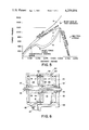
- FIG. 5 is a representative graph indicating the characteristics of the tool operating forces.
- FIG. 6 is a fragmentary cross-sectional view similar to FIG. 1, but showing a modified form of tool structure.
- the pneumatic power tool 10 includes a cylindrical housing or body 11 which comprises a plurality of discrete segments 12 in coaxial alignment with each other and with a front end cap 13 and a rear end cap 14.
- the end caps have apertured ears 15 to accommodate stay-bolts 16, several of which are circumferentially spaced from each other about the body and serve to secure and clamp the parts 12, 13 and 14 into the desired assembled relationship to form the housing 11.
- a disk-shaped baffle plate 17 having a peripheral, diametrically-extending flange portion 18 is disposed and clamped intermediate the adjacent ends 19 of each pair of cylindrical segments 12, so as to partition the interior of the housing 11 into a front chamber 20, a middle chamber 21 and a rear chamber 22. It will be understood that there may be more or less of such baffle plates forming more or less of such chambers, the illustrated embodiment being examplary only.
- each chamber is slidably mounted a disk-shaped plate or piston.
- the piston for the front chamber is designated 23; the middle chamber piston is 24; and the rear piston is designated 25.
- the pistons 23-25 could be uniformly alike or may have dissimilarities from each other.
- a tubular stem or tie rod 26 which traverses the central openings 27 and 28 provided in the baffles 17 and the pistons 23-25, respectively.
- the stem 26 has a work-engaging forward externally threaded end 29 which projects outwardly through the front cap 13 and which is operatively associated with a suitable nosepiece.
- the cap 13 has threadedly secured thereto a guide bearing 30 which slidably accommodates the longitudinal movement of a lock nut 31 which is secured to the threaded end 29 of the stem.
- the opposite or rearward end 32 of the rod 26 projects through an opening or bore 33 in the rear end cap 14 and communicates with a low pressure or vacuum space 34 for a purpose to be described.
- a lock nut 35 Adjacent this rearward end, a lock nut 35 is threadedly secured to the rod and coacts with the other lock nut 31 to clamp the pistons and associated parts into an assembly 36 fixed to and movable with the rod 26.
- a recessed or flanged collar 37 is carried on the stem 26 and interposed between each of the lock nuts and their contiguous pistons 23 or 25.
- a tubular piston spacer element 38 having end portions 39 of reduced diameter extends between each pair of pistons, with the portions 39 received in the central opening or bore 28 of the piston and spaced from each other and from the collars 37 to provide a circumferentially-extending fluid passageway 41 within the bore 28.
- Each passageway 41 has separate communication with an annular passageway or passageways 42 extending longitudinally of each spacer 38.
- An O-ring 43 between adjacent ends of the spacers 38 serves to seal these ends and make the passageway 42 continuous and air-tight.
- Each piston is provided with an angularly directed notch or channel 44 on pressure face 45 extending into communication with the passageway 41.
- the notch 44 on any one of the pistons can be of a different size or cross-sectional area than the notch on any other, so as to act as an entry orifice control for metering the volume flow into each chamber independently of the others.
- the sized notches may be arranged to permit rapid pressure and force buildup on pistons 23 and 24 and a lagging force buildup on piston 25 to achieve desired speed control of the work operation while at the same time establishing a greater uniformity and sensitivity in the control of the operating force required for the work.
- each of the separate spacer elements may also be sized to have a metering function for fluid flow control, thus increasing the versatility of the tool.
- valve entry port or orifice 46 By utilizing individual imput and exhaust metering orifices for each chamber, there is no longer need to rely solely upon the size of the valve entry port or orifice 46 for speed and volume control.
- the port 46 can be relatively oversize, thereby reducing the initial precipitation of the aspirated lubricant mist which is induced by a sudden severe restriction in the size of the valve port.
- the larger permissible valve port allows the air to carry lubricant mist in adequate amounts to the more remote chambers 21 and 22 without the lubricant depletion resulting from premature and excessive lubricant precipitation which would otherwise occur in the front chamber 20.
- valve 47 Any suitable valving arrangement 47, schematically illustrated, can be used, using conventional forms of button or trigger actuation or the like.
- compressed air is directed through the entry port 46 into the front chamber 20 to exert force on the pressure face 45 of piston 23.
- the air enters the passageway 42 through the notch 44 of piston 23 and its associated passage 41; it enters chamber 21 through passage 41 and notch 44 of piston 24; and enters chamber 22 through the like passageways of piston 25.
- the orifices leading to each of the chambers may vary in size so that, for example, the pressure buildup in chambers 20 and 21 may approach maximum well before chamber 22.
- a further measure of control of the tool is provided by the rate of venting or exhaust permitted by the exhaust orifices which can be sized during manufacture to achieve predetermined operating performance.
- the front chamber 20 contains entrapped air between the piston 23 and its baffle plate 17. As the piston 23 is urged rearwardly or to the right (as viewed in FIG. 1) by the entry of the compressed air through port 46, the entrapped air behind the piston is forced out and exhausts through passageway 55 into the restricted exhaust passageway or orifice 58 provided in the valve 47. The size of this exhaust orifice 58 establishes the rate of discharge or venting of the entrapped air from chamber 20 and thereby controls the rate of piston displacement.
- the entrapped air in the middle chamber 21 is vented at a controlled rate through sized exhaust orifice 56 which is provided n the periphery of the contiguous baffle plate 17.
- the exhaust orifices are sized to vent slowly and resist piston displacement. If a slow buildup of force and rapid displacement is desired, the exhaust orifices are sized for rapid venting. However, some intermediate degree of performance between these operational extremes is more usually desired and can be accomplished with a high degree of precision by predetermined sizing of all or some of the exhaust orifices.
- the vacuum in the portion 34 of chamber 22 also serves a second purpose.
- the bore 50 of the hollow rod 26 is exposed to the vacuum at its end 32 and will draw or suck the fractured rivet shanks or the like from the forward end of the rod toward the rear of the tool for ejection.
- an air-tight container or boot 51 can be provided on the end cap 14 to retain the ejected scrap.
- Any suitable form of filter 40 is interposed between tool chamber 34 and the boot 51 to prevent the scrap or dirt from entering the vacuum passageways. The close proximity of the scrap reservoir or boot 51 to the nosepiece of the tool increases suction efficiency and eliminates long vacuum lines.
- Blind rivet setting forces are a function of mandrel size and physical characteristics of the rivet material.
- most tool have a gradual force buildup, as shown in curve A, which causes displacement until rivet setting and mandrel fracture occurs; but the force of the tool still continues to increase beyond this point, without any useful purpose or accomplishment.
- this continued application of force not only consumes energy unnecessarily, but results in undesirable impact and shock on the elements of the tool as it reaches the end of its stroke, after sudden release of work load.
- Curve B represents the necessary force values required to be imposed on the rivet to achieve setting of the rivet. It will be noted that the initial tensile forces peak with relatively little displacement. The force requirement then diminishes and then again increases as the elastic limit of the rivet is approached.
- An improved unitary shock absorber 52 is provided, made of rubber or other elastomeric material, and consisting of circumferentially spaced lobes 53 created by slotting as at 54. At the initial instant of impact of piston 25 on the shock absorber, its reaction force is substantially zero. As the lobes 53 are displaced by the pistn face 48, the lobes are deformed and caused to bulge into contact with each other producing a gradually increasing reactive force in response to increased deformation and displacement until the withdrawal movement of the pistonassembly is arrested, and then partially reversed when the air pressure is relieved. As illustrated, the shock absorber is suitably secured to the interior face of the end cap 14.
- valve port 46 When the retraction stroke is completed, the flow of compressed air through valve port 46 is shut off and the compressed air is directed through passageway 55 into chamber 20 rearwardly of the piston 23 to cause advance and return of the piston assembly 36 to loading position.
- This arrangement eliminates the need for a separate return spring and reduces the cost and number of parts required for the tool. More importantly, the elimination of a return spring means that the retraction force applied to the piston assembly need be of a magnitude sufficient only to perform the work loads and need not be increased to overcome the additional load which would be impressed on the piston assembly by energization of a return spring.
- the channel 55 may also serve, if desired, as a relief vent to atmosphere through valve 47 for chamber 20 during retraction of piston 23.
- baffle plates 17 also reduce the cost of the tool and enhances its utility.
- the cost of a unitary cylinder body is eliminated, as well as the cost of internal machining for baffle retaining rings and the rings themselves, as required in U.S. Pat. No. 3,430,539.
- the increased clamping area provided by the baffles 17 interposed between cylinder body segments 12, result in greater rigidity of baffle plate structure and more precise positioning.
- One or more of the baffles 17 can be slotted, as at 56, to provide a relief vent to atmosphere for its associated chamber, rearwardly of the piston.
- One or more of the baffles may also be utilized for example as at opening 57, for the connection of probes, sensors or recording instruments for monitoring pressure or vacuum, if desired. Any such modifications of the baffle plates are readily and economically accomplished by machining operations on the baffle 17 prior to assembly. By utilizing modules of segments 12 and baffle elements 17, the tool can be customized to include desired features and a greater or lesser number of chambers and pistons to meet particular job requirements.
- FIG. 6 there is shown a modified form of the invention which utilizes a continuous cylindrical body 59 in lieu of the segmented body structure 11 previously described.
- split locking rings 60 are mounted in machined recesses 61 interiorly of the body and closely adjacent the baffles 17 to retain them against displacement in at least one direction.
- the body can be apertured, as at 62, to vent chambers, such as 21, during operation of the tool.
- FIG. 6 there is also shown a modified form of spacer element 63 whose bore is milled or broached to provide one or more longitudinally-extending recesses 64 which serve as air channels or manifolds in the same manner as the previously described drilled openings 42 of spacers 38.
- spacer element 63 whose bore is milled or broached to provide one or more longitudinally-extending recesses 64 which serve as air channels or manifolds in the same manner as the previously described drilled openings 42 of spacers 38.
- the recesses 64 of one spacer element 63 may be of different cross-sectional area than the recesses 64 of another spacer 63 to achieve predetermined orifice control of air input to the separate chambers of the multi-piston cylinder, just as the previously described passageways 42 may be uniform or of different size in different spacers 38.
- the forward threaded end 29 of the stem 26 has secured thereto a conventional collet assembly 65 which serves to grip the mandrel of the rivet in the operation of tool, in a manner known to the art.
- a liner sleeve or tube 66 has its forward end 67 projecting into the collet to receive the end of the mandrel of the rivet.
- the tube 66 fits slidably into the bore 50 of the stem 26 and extends therethrough toward the rearward end 32 of the stem to provide a passageway 68 for the scrap.
- a stop collar 69 is fixed to the exterior of sleeve 66 so as to abut the forward end 29 of the stem 26 and limit rearward movement of the sleeve relatively to the stem.
- a resilient ring or gasket 70 is mounted on the sleeve 66 between the collar 69 and end 29 of the stem to serve a dual function.
- the ring 70 serves as a shock absorber to relieve the impact force between collar 69 and stem 26 which occurs when the rivet mandrel is fractured.
- the ring 70 serves as a seal to contain the low pressure or vacuum to which the passageway 68 and bore 50 is exposed, as previously described.
- a compression coil spring 71 has one end thereof seated on the stop collar 69 and its other end seated on a collet shoulder portion 72 so as to yieldably retain the collar in abutment with the ring 70 and compress it against the end 29 of the stem.
- the collar 69 is provided with a forward extension 73 of reduced diameter to act as a guide for the spring 71.
Abstract
Description
Claims (13)
Priority Applications (1)
| Application Number | Priority Date | Filing Date | Title |
|---|---|---|---|
| US06/044,246 US4259858A (en) | 1979-05-31 | 1979-05-31 | Vacuum-pneumatic power tool |
Applications Claiming Priority (1)
| Application Number | Priority Date | Filing Date | Title |
|---|---|---|---|
| US06/044,246 US4259858A (en) | 1979-05-31 | 1979-05-31 | Vacuum-pneumatic power tool |
Publications (1)
| Publication Number | Publication Date |
|---|---|
| US4259858A true US4259858A (en) | 1981-04-07 |
Family
ID=21931305
Family Applications (1)
| Application Number | Title | Priority Date | Filing Date |
|---|---|---|---|
| US06/044,246 Expired - Lifetime US4259858A (en) | 1979-05-31 | 1979-05-31 | Vacuum-pneumatic power tool |
Country Status (1)
| Country | Link |
|---|---|
| US (1) | US4259858A (en) |
Cited By (20)
| Publication number | Priority date | Publication date | Assignee | Title |
|---|---|---|---|---|
| US4497197A (en) * | 1983-02-18 | 1985-02-05 | Chicago Pneumatic Tool Company | Pneumatic hydraulic hand-held power unit |
| US4531541A (en) * | 1984-02-16 | 1985-07-30 | Ingersoll-Rand Company | Plate-type valve, and an improved valve seat and a valve seat assembly therefor |
| US4535925A (en) * | 1983-08-10 | 1985-08-20 | Micro Plastics, Inc. | Semi-automatic pneumatic expansion rivet gun |
| US4587829A (en) * | 1985-07-03 | 1986-05-13 | Huck Manufacturing Co. | Lightweight, high pressure fastener installation tool and system |
| US4887450A (en) * | 1988-03-31 | 1989-12-19 | Textron, Inc. | Fastener stem collection apparatus and method |
| US5127803A (en) * | 1990-02-16 | 1992-07-07 | Walter James C | Pump tool |
| US5323946A (en) * | 1992-10-19 | 1994-06-28 | Emhart Inc. | Blind rivet setting tool |
| US5333684A (en) * | 1990-02-16 | 1994-08-02 | James C. Walter | Downhole gas separator |
| US5890414A (en) * | 1997-08-12 | 1999-04-06 | The United States Of America As Represented By The Secretary Of The Navy | Stop cylinder and piston assembly |
| USD423896S (en) * | 1998-10-21 | 2000-05-02 | Emhart Inc | Rivet setting tool |
| US6676000B2 (en) * | 2001-04-09 | 2004-01-13 | Bollhoff Gmbh | Drive system for a fastening tool |
| US20040035902A1 (en) * | 2001-03-29 | 2004-02-26 | Intel Corporation | Fastener installation tool |
| US20040139590A1 (en) * | 2003-01-21 | 2004-07-22 | Ahmed Eldessouky | Nut-plate riveter |
| US20040148747A1 (en) * | 2002-10-29 | 2004-08-05 | Woyciesjes James N. | Rivet tool with remote intensifier auto fill/recharge system |
| US20050215097A1 (en) * | 2002-02-12 | 2005-09-29 | Anatoly Gosis | Installation, insulation displacement, and terminating tool |
| US7062843B1 (en) * | 2005-02-14 | 2006-06-20 | Yu-Ching Lin | Straight type riveting gun |
| US20080148697A1 (en) * | 2006-12-20 | 2008-06-26 | Chia Sheng Liang | Filter for Nail Gun |
| US20140250830A1 (en) * | 2013-03-06 | 2014-09-11 | Precitec Corp. | Crimp control apparatus |
| CN109454194A (en) * | 2018-07-27 | 2019-03-12 | 宾科精密部件(中国)有限公司 | The pressure riveting device of fluid pressure actuated |
| US11491533B2 (en) * | 2019-12-18 | 2022-11-08 | Spirit Aerosystems, Inc. | Fastener insertion gun for installing fasteners in vehicle structures |
Citations (7)
| Publication number | Priority date | Publication date | Assignee | Title |
|---|---|---|---|---|
| US3415102A (en) * | 1966-09-23 | 1968-12-10 | United Shoe Machinery Corp | Tools for setting blind rivets |
| US3430539A (en) * | 1967-11-02 | 1969-03-04 | Scovill Manufacturing Co | Pneumatic tool |
| US3457763A (en) * | 1966-11-30 | 1969-07-29 | Scovill Manufacturing Co | Blind rivet tool |
| US3523441A (en) * | 1968-05-10 | 1970-08-11 | Star Expansion Ind Corp | Blind rivet air tool |
| US3554088A (en) * | 1968-11-06 | 1971-01-12 | James Henry Bruyn | Air tool |
| US3630067A (en) * | 1969-05-10 | 1971-12-28 | Usm Corp | Fluid pressure operated head for setting mandrel rivets |
| US4062217A (en) * | 1976-07-15 | 1977-12-13 | Ebbert Robert J | Riveting station assembly |
-
1979
- 1979-05-31 US US06/044,246 patent/US4259858A/en not_active Expired - Lifetime
Patent Citations (7)
| Publication number | Priority date | Publication date | Assignee | Title |
|---|---|---|---|---|
| US3415102A (en) * | 1966-09-23 | 1968-12-10 | United Shoe Machinery Corp | Tools for setting blind rivets |
| US3457763A (en) * | 1966-11-30 | 1969-07-29 | Scovill Manufacturing Co | Blind rivet tool |
| US3430539A (en) * | 1967-11-02 | 1969-03-04 | Scovill Manufacturing Co | Pneumatic tool |
| US3523441A (en) * | 1968-05-10 | 1970-08-11 | Star Expansion Ind Corp | Blind rivet air tool |
| US3554088A (en) * | 1968-11-06 | 1971-01-12 | James Henry Bruyn | Air tool |
| US3630067A (en) * | 1969-05-10 | 1971-12-28 | Usm Corp | Fluid pressure operated head for setting mandrel rivets |
| US4062217A (en) * | 1976-07-15 | 1977-12-13 | Ebbert Robert J | Riveting station assembly |
Cited By (30)
| Publication number | Priority date | Publication date | Assignee | Title |
|---|---|---|---|---|
| US4497197A (en) * | 1983-02-18 | 1985-02-05 | Chicago Pneumatic Tool Company | Pneumatic hydraulic hand-held power unit |
| US4535925A (en) * | 1983-08-10 | 1985-08-20 | Micro Plastics, Inc. | Semi-automatic pneumatic expansion rivet gun |
| US4531541A (en) * | 1984-02-16 | 1985-07-30 | Ingersoll-Rand Company | Plate-type valve, and an improved valve seat and a valve seat assembly therefor |
| US4587829A (en) * | 1985-07-03 | 1986-05-13 | Huck Manufacturing Co. | Lightweight, high pressure fastener installation tool and system |
| US4887450A (en) * | 1988-03-31 | 1989-12-19 | Textron, Inc. | Fastener stem collection apparatus and method |
| US5127803A (en) * | 1990-02-16 | 1992-07-07 | Walter James C | Pump tool |
| US5333684A (en) * | 1990-02-16 | 1994-08-02 | James C. Walter | Downhole gas separator |
| US5323946A (en) * | 1992-10-19 | 1994-06-28 | Emhart Inc. | Blind rivet setting tool |
| US5890414A (en) * | 1997-08-12 | 1999-04-06 | The United States Of America As Represented By The Secretary Of The Navy | Stop cylinder and piston assembly |
| USD423896S (en) * | 1998-10-21 | 2000-05-02 | Emhart Inc | Rivet setting tool |
| US20040035902A1 (en) * | 2001-03-29 | 2004-02-26 | Intel Corporation | Fastener installation tool |
| US20040045728A1 (en) * | 2001-03-29 | 2004-03-11 | Intel Corporation | Fastener installation tools, systems, and methods of use |
| US7407070B2 (en) | 2001-03-29 | 2008-08-05 | Intel Corporation | Fastener installation tool |
| US20060175068A1 (en) * | 2001-03-29 | 2006-08-10 | Intel Corporation | Fastener installation tools, systems, and methods of use |
| US7048073B2 (en) * | 2001-03-29 | 2006-05-23 | Intel Corporation | Fastener installation systems |
| US6676000B2 (en) * | 2001-04-09 | 2004-01-13 | Bollhoff Gmbh | Drive system for a fastening tool |
| US20050215097A1 (en) * | 2002-02-12 | 2005-09-29 | Anatoly Gosis | Installation, insulation displacement, and terminating tool |
| US7251879B2 (en) * | 2002-02-12 | 2007-08-07 | Illinois Tool Works Inc | Installation, insulation displacement, and terminating tool having piston-cylinder driving assembly |
| US20040148747A1 (en) * | 2002-10-29 | 2004-08-05 | Woyciesjes James N. | Rivet tool with remote intensifier auto fill/recharge system |
| US7024742B2 (en) * | 2002-10-29 | 2006-04-11 | Newfrey Llc | Rivet tool with remote intensifier auto fill/recharge system |
| US6907648B2 (en) | 2003-01-21 | 2005-06-21 | Textron Inc. | Riveting tool such as a nut plate riveter |
| WO2004067206A3 (en) * | 2003-01-21 | 2004-09-02 | Textron Inc | Nut-plate riveter |
| WO2004067206A2 (en) * | 2003-01-21 | 2004-08-12 | Textron Inc. | Nut-plate riveter |
| US20040139590A1 (en) * | 2003-01-21 | 2004-07-22 | Ahmed Eldessouky | Nut-plate riveter |
| US7062843B1 (en) * | 2005-02-14 | 2006-06-20 | Yu-Ching Lin | Straight type riveting gun |
| US20080148697A1 (en) * | 2006-12-20 | 2008-06-26 | Chia Sheng Liang | Filter for Nail Gun |
| US20140250830A1 (en) * | 2013-03-06 | 2014-09-11 | Precitec Corp. | Crimp control apparatus |
| US9266634B2 (en) * | 2013-03-06 | 2016-02-23 | Precitec Corp. | Crimp control apparatus |
| CN109454194A (en) * | 2018-07-27 | 2019-03-12 | 宾科精密部件(中国)有限公司 | The pressure riveting device of fluid pressure actuated |
| US11491533B2 (en) * | 2019-12-18 | 2022-11-08 | Spirit Aerosystems, Inc. | Fastener insertion gun for installing fasteners in vehicle structures |
Similar Documents
| Publication | Publication Date | Title |
|---|---|---|
| US4259858A (en) | Vacuum-pneumatic power tool | |
| US3457763A (en) | Blind rivet tool | |
| US4174098A (en) | Shock absorber and mounting means therefor | |
| US3929057A (en) | Hydraulic brake mechanism for an air cylinder | |
| US4597263A (en) | Pull type installation tool | |
| US3254522A (en) | Hydraulic pop riveters | |
| US3636707A (en) | Power device | |
| US3554088A (en) | Air tool | |
| US3557597A (en) | Riveting apparatus | |
| EP3590625B1 (en) | Riveting tool chuck and riveting tool | |
| EP2174730B1 (en) | Reaction device for forming equipment | |
| US4355564A (en) | Pneumatic reciprocating mechanism | |
| US4263801A (en) | Hydraulic riveter | |
| US5775441A (en) | Power driven striking tool | |
| US5623861A (en) | Pneumatic cylinder and control valve therefor | |
| GB2090940A (en) | Air pressure shock absorber | |
| US4424737A (en) | Stroke cushioning apparatus for hydraulic cylinders | |
| US3430539A (en) | Pneumatic tool | |
| US6027105A (en) | Impact damper | |
| US4167891A (en) | Hydraulic actuator | |
| US10202988B2 (en) | Cushion mechanism for a hydraulic cylinder | |
| US2877750A (en) | Hammer and buffer mechanism | |
| US4681172A (en) | Cushioning device for use with a pneumatic impact tool or the like | |
| GB2129914A (en) | Recoil brake system for gun | |
| US3362211A (en) | Tool construction |
Legal Events
| Date | Code | Title | Description |
|---|---|---|---|
| STCF | Information on status: patent grant |
Free format text: PATENTED CASE |
|
| AS | Assignment |
Owner name: FABCO-AIR INC.A CORP.OF OHIO Free format text: ASSIGNMENT OF ASSIGNORS INTEREST.;ASSIGNOR:FREEMAN, RICHARD B.;REEL/FRAME:003853/0099 Effective date: 19810506 Owner name: FABCO-AIR INC.A CORP.OF OHIO, OHIO Free format text: ASSIGNMENT OF ASSIGNORS INTEREST;ASSIGNOR:FREEMAN, RICHARD B.;REEL/FRAME:003853/0099 Effective date: 19810506 |
|
| AS | Assignment |
Owner name: FABCO-AIR, INC., A CORP. OF DE. Free format text: ASSIGNMENT OF ASSIGNORS INTEREST.;ASSIGNOR:FABCO-AIR, INC.,;REEL/FRAME:003853/0912 Effective date: 19810507 |
|
| AS | Assignment |
Owner name: FABCO-AIR, INC., A CORP. OF OH. Free format text: ASSIGNMENT OF ASSIGNORS INTEREST.;ASSIGNOR:FABCO-AIR, INC.;REEL/FRAME:003854/0677 Effective date: 19810507 |
|
| AS | Assignment |
Owner name: SCHMIDT, ALFRED W., 3716 N.E. 49TH RD., GAINESVILL Free format text: ASSIGNS TO EACH ASSIGNEE THE INTEREST OPPOSITE HIS RESPECTIVE NAME, SUBJECT TO CONDITIONS UNDER SECURITY AGREEMENT RECITED,;ASSIGNOR:BBBD, INC., AN OH CORP. (FORMERLY K/A FABCO-AIR INC.);REEL/FRAME:003905/0158 Effective date: 19810529 Owner name: SCHMIDT, WILLIAM R., 3716 N.E. 49TH ROAD, GAINESVI Free format text: ASSIGNS TO EACH ASSIGNEE THE INTEREST OPPOSITE HIS RESPECTIVE NAME, SUBJECT TO CONDITIONS UNDER SECURITY AGREEMENT RECITED,;ASSIGNOR:BBBD, INC., AN OH CORP. (FORMERLY K/A FABCO-AIR INC.);REEL/FRAME:003905/0158 Effective date: 19810529 Owner name: SCHMIDT, ROBER A., 3716 N.E. 49TH ROAD, GAINESVILL Free format text: ASSIGNS TO EACH ASSIGNEE THE INTEREST OPPOSITE HIS RESPECTIVE NAME, SUBJECT TO CONDITIONS UNDER SECURITY AGREEMENT RECITED,;ASSIGNOR:BBBD, INC., AN OH CORP. (FORMERLY K/A FABCO-AIR INC.);REEL/FRAME:003905/0158 Effective date: 19810529 Owner name: SCHMIDT, DAVID J., 3716 N.E. 49TH ROAD, GAINESVILL Free format text: ASSIGNS TO EACH ASSIGNEE THE INTEREST OPPOSITE HIS RESPECTIVE NAME, SUBJECT TO CONDITIONS UNDER SECURITY AGREEMENT RECITED,;ASSIGNOR:BBBD, INC., AN OH CORP. (FORMERLY K/A FABCO-AIR INC.);REEL/FRAME:003905/0158 Effective date: 19810529 Owner name: HARKER, BARBARA A., 3716 N.E. 49TH RD., GAINESVILL Free format text: ASSIGNS TO EACH ASSIGNEE THE INTEREST OPPOSITE HIS RESPECTIVE NAME, SUBJECT TO CONDITIONS UNDER SECURITY AGREEMENT RECITED,;ASSIGNOR:BBBD, INC., AN OH CORP. (FORMERLY K/A FABCO-AIR INC.);REEL/FRAME:003905/0158 Effective date: 19810529 Owner name: FABCO-AIR INC., A OH CORP. Free format text: CHANGE OF NAME;ASSIGNOR:BBBD, INC.;REEL/FRAME:003905/0159 Effective date: 19810508 Owner name: FABCO-AIR INC. Free format text: CHANGE OF NAME;ASSIGNOR:BBBD, INC.;REEL/FRAME:003905/0159 Effective date: 19810508 |