US4289138A - Electrode assembly for temporary pacing and heart measurements - Google Patents
Electrode assembly for temporary pacing and heart measurements Download PDFInfo
- Publication number
- US4289138A US4289138A US06/157,504 US15750480A US4289138A US 4289138 A US4289138 A US 4289138A US 15750480 A US15750480 A US 15750480A US 4289138 A US4289138 A US 4289138A
- Authority
- US
- United States
- Prior art keywords
- wires
- electrode assembly
- catheter
- ferrules
- wire
- Prior art date
- Legal status (The legal status is an assumption and is not a legal conclusion. Google has not performed a legal analysis and makes no representation as to the accuracy of the status listed.)
- Expired - Lifetime
Links
- 210000002216 heart Anatomy 0.000 title description 13
- 238000005259 measurement Methods 0.000 title description 4
- 239000000463 material Substances 0.000 claims abstract description 3
- 238000009413 insulation Methods 0.000 claims description 8
- 239000011324 bead Substances 0.000 claims description 4
- 238000003780 insertion Methods 0.000 claims description 2
- 230000037431 insertion Effects 0.000 claims description 2
- 239000012774 insulation material Substances 0.000 claims description 2
- 239000004020 conductor Substances 0.000 claims 1
- 239000000523 sample Substances 0.000 description 11
- 210000004204 blood vessel Anatomy 0.000 description 5
- 239000004568 cement Substances 0.000 description 5
- 210000005245 right atrium Anatomy 0.000 description 4
- 210000005240 left ventricle Anatomy 0.000 description 3
- 210000005241 right ventricle Anatomy 0.000 description 3
- 210000000591 tricuspid valve Anatomy 0.000 description 3
- 230000002861 ventricular Effects 0.000 description 3
- 239000004593 Epoxy Substances 0.000 description 2
- 239000004972 Polyurethane varnish Substances 0.000 description 2
- 230000001746 atrial effect Effects 0.000 description 2
- 230000008602 contraction Effects 0.000 description 2
- 238000004804 winding Methods 0.000 description 2
- RYGMFSIKBFXOCR-UHFFFAOYSA-N Copper Chemical compound [Cu] RYGMFSIKBFXOCR-UHFFFAOYSA-N 0.000 description 1
- 206010061216 Infarction Diseases 0.000 description 1
- 102100026827 Protein associated with UVRAG as autophagy enhancer Human genes 0.000 description 1
- 101710102978 Protein associated with UVRAG as autophagy enhancer Proteins 0.000 description 1
- BQCADISMDOOEFD-UHFFFAOYSA-N Silver Chemical compound [Ag] BQCADISMDOOEFD-UHFFFAOYSA-N 0.000 description 1
- 239000000956 alloy Substances 0.000 description 1
- 229910045601 alloy Inorganic materials 0.000 description 1
- DMFGNRRURHSENX-UHFFFAOYSA-N beryllium copper Chemical compound [Be].[Cu] DMFGNRRURHSENX-UHFFFAOYSA-N 0.000 description 1
- ZMDCATBGKUUZHF-UHFFFAOYSA-N beryllium nickel Chemical compound [Be].[Ni] ZMDCATBGKUUZHF-UHFFFAOYSA-N 0.000 description 1
- 230000017531 blood circulation Effects 0.000 description 1
- 210000005242 cardiac chamber Anatomy 0.000 description 1
- 206010061592 cardiac fibrillation Diseases 0.000 description 1
- 238000010276 construction Methods 0.000 description 1
- 230000002600 fibrillogenic effect Effects 0.000 description 1
- 230000006870 function Effects 0.000 description 1
- 210000002837 heart atrium Anatomy 0.000 description 1
- 230000004217 heart function Effects 0.000 description 1
- 210000003709 heart valve Anatomy 0.000 description 1
- 230000007574 infarction Effects 0.000 description 1
- 238000004519 manufacturing process Methods 0.000 description 1
- 229910052751 metal Inorganic materials 0.000 description 1
- 239000002184 metal Substances 0.000 description 1
- 210000004115 mitral valve Anatomy 0.000 description 1
- 238000012986 modification Methods 0.000 description 1
- 230000004048 modification Effects 0.000 description 1
- 210000000056 organ Anatomy 0.000 description 1
- 229910052709 silver Inorganic materials 0.000 description 1
- 239000004332 silver Substances 0.000 description 1
- 210000003462 vein Anatomy 0.000 description 1
Images

Classifications
-
- A—HUMAN NECESSITIES
- A61—MEDICAL OR VETERINARY SCIENCE; HYGIENE
- A61N—ELECTROTHERAPY; MAGNETOTHERAPY; RADIATION THERAPY; ULTRASOUND THERAPY
- A61N1/00—Electrotherapy; Circuits therefor
- A61N1/02—Details
- A61N1/04—Electrodes
- A61N1/05—Electrodes for implantation or insertion into the body, e.g. heart electrode
- A61N1/056—Transvascular endocardial electrode systems
Definitions
- This invention concerns an electrode assembly adapted for temporary heart pacing and making measurements of blood vessels.
- a generally known typical catheter type flow sensor adapted for temporary pacing applications is comprised of a bifilar probe terminating in a wire loop in a lenticular shape.
- the loop is collapsed when inside the catheter and when it leaves the catheter and enters into a chamber of the heart or into a blood vessel it takes a lenticular shape.
- the loop is withdrawn into the catheter, there is always the hazard that a leaf of a heart valve or other protrusion will be caught in the loop.
- the present invention is directed at overcoming the above and other difficulties and disadvantages of the prior loop type of catheter probes, and for providing an improved electrode assembly which can employ a catheter of smaller external diameter than that required by loop types of probes.
- an electrode assembly which can function as a temporary heart pacer as well as an instrument for measuring the flow in blood vessels.
- the assembly may employ insulated bifilar, trifilar, quadrafilar or the like wire terminating in free ends of different lengths.
- On the end of each wire is a ferrule.
- the ferrules are staggered or spaced in position lengthwise of and inside a catheter during insertion through the catheter, which may be positioned into a heart chamber via a blood vessel.
- the internal diameter of the catheter required to accomodate the ferrules and adjacent wires of the bifilar, trifilar or quadrafilar wire is less than required to accomodate a wire loop of a corresponding loop type probe.
- Another object of the present invention is to provide an electrode assembly of the type described wherein the free ends of the wires have different lengths.
- a further object of the present invention is to provide an electrode assembly as described, wherein ferrules are secured to the free ends of the wires, and wherein further ferrules are mounted on the other ends of the wires.
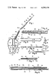
- FIG. 1 is a side elevational view of an electrode assembly embodying the invention, parts being shown in section and other parts being broken away to show internal construction;
- FIG. 2 is an enlarged longitudinal sectional view of an end portion of the electrode assembly
- FIGS. 3, 5, and 6 are plan views showing the wires at successive stages of assembly
- FIG. 4 is an enlarged cross section taken along line 4--4 of FIG. 3;
- FIG. 7 is an enlarged axial sectional view of one end of the electrode assembly
- FIG. 8 is an enlarged axial view of the other end of the electrode assembly taken along line 8--8 of FIG. 1.
- FIG. 9 is another embodiment of the electrode assembly 10' similar to FIG. 1;
- FIG. 10 is a further embodiment of the electrode assembly 10".
- an electrode assembly generally designated as reference numeral 10 which includes a pair of insulated wires 12a, 12b bound together in a bifilar array 12 by an insulated fine wire winding 14.
- the winding 14 terminates short of the free ends 16a, 16b of the bifilar array 12.
- the end 16a is longer than the end 16b.
- a ferrule 18 is mounted on each of the wire ends 16a, 16b. As best shown in FIG. 7, the ferrule 18 has a cylindrical metal body into which the end 16a or 16b of the respective wire 12a or 12b is inserted.
- a coat of insulation 20 on the wire 12 is scraped away at the wire end and a conductive cement 22 such as silver filled epoxy is applied to the bare wire end on which is axially mounted cylindrical ferrule 18. At both ends of the ferrule 18 are applied a respective bead 23, 24 of an insulation material such as epoxy.
- FIGS. 1 and 8 At the other end of the bifilar array 12 are two further cylindrical ferrules 24 and 26; see FIGS. 1 and 8. These ferrules may be connected to an external electrical circuit.
- Ferrule 24 is mounted on the other end of bifilar wires 12a, 12b.
- the insulation 20 is scraped away from the end of the wire 12a, and the bared wire is coated with a conductive cement 30 to secure the ferrule 24 on the wire end.
- the ferrule 24 encircles both wires 12a, 12b, but is insulated from the wire 12b. Beads 32, 34 of an insulation cement are placed at opposite ends of the ferrule 24. Axially spaced from the ferrule 24 is the cylindrical ferrule 26.
- Insulation 20 is scraped away from a portion of wire 12b and the ferrule 26 is mounted on the bifilar wires 12a and 12b and secured in place on the bared portion of wire 12b by a conductive cement 36.
- a respective bead 38, 39 of insulation cement is applied to an opposite end of the ferrule 26.
- the binding wire 14 is also removed from the portions of the bifilar wires 12a and 12b carrying the ferrules 24 and 26.
- FIG. 2 shows the ferrules 18 disposed in longitudinal spaced position inside a flexible catheter 40.
- the flexible catheter 40 may be inserted through a vein 42 (FIG. 1) through the right atrium 41 to the tricuspid valve 45.
- the electrode assembly 10 will pass axially through the catheter 40 and out of its free end through the tricuspid valve 45 into the right ventricle 44.
- There the free end of the bifilar wire probe will separate and the ferrules 18 will contact the opposite spaced walls 46 of the right ventricle 44.
- the catheter 40 may then be removed from the heart.
- FIGS. 3 and 4 show one step in the method of fabricating the electrode assembly.
- Fine springy wire 12' made of beryllium copper or beryllium nickel or other suitable alloy ranging from 0.004" to 0.125" is coated with an insulating layer 20 such as polyurethane varnish.
- the wire 12' is bent to form a loop 48.
- the wire sections 12a and 12b are placed side-by-side as shown in FIG. 5 and wound with the fine binding wire 14 such as 0.002" insulated copper wire.
- the binding wire 14 may be bonded to the wire sections 12a and 12b with several cured coats of an insulated material (not shown), such as polyurethane varnish which was used for the insulation 20.
- the loop 48' is then cut on line A--A so that the wire end 16a will be longer than the wire end 16b as shown in FIG. 6. Then the insulation 20 is scraped from the wire ends 16a and 16b and the ferrules 18 are mounted on the wire ends 16a, 16b as shown in FIGS. 1 and 7.
- the lengths of the wire ends 16a and 16b are critical. One wire end 16a should be longer than the other end 16b by at least the length of one ferrule 18, so that the ferrules occupy minimum space inside the catheter 40.
- the axial spacing of the contact ferrules 18 permit the ferrules 18 to pass through a smaller catheter 40 than would be needed if both of the ferrules 18 were in a side-by-side position against each other when passing through the catheter 40.
- the arrangement described provides better contact between the walls of the chamber 44 than prior loop type probes.
- the free ends of the wires can open wider than maximum diameter of a prior closed loop type of probe.
- the ferrules 18 make a better contact with the chamber walls than the narrow sides of a closed wire loop because the ferrules have a larger surface area than the electrodes of the prior loop type catheter probe.
- the free wire ends will not catch on protrusions in the chamber walls as presently possible with closed wire loops.
- the free wire ends bearing ferrules 18 will pass through a catheter of narrower diameter than one sized to accomodate a probe with closed wire loop.
- the use of a catheter of narrower diameter facilitates passage of the catheter through vessels of the body such as chambers of the heart, or to other organs.
- FIG. 9 illustrates another embodiment of the electrode assembly 10' wherein the binding wire 14 has been formed into a terminal 16c in order to have bipolar pacing. That is to say, when the electrode assembly 10 of FIG. 1 is pulsed by a D.C. Voltage each of the terminals 16a and 16b have a different polarity.
- the terminal 16a and 16b may have one polarity and the terminal 16c which is located in the blood vessel just outside of the heart has the other polarity or terminal 16a and 16c may have the same polarity and terminal 16b the other polarity or terminal 16b and 16c may have the same polarity and terminal 16a the other polarity.
- the terminal 16c must be located outside of the heart.
- an electrode assembly 10" as illustrated in FIG. 10 may be utilized.
- the electrode assembly 10" may be made from quadrafilar wires and is comprised of terminals 16a, 16b, 16d, and 16e.
- the terminals 16d and 16e are identical to the terminals 16a and 16b respectively.
- the other end of the electrode assembly 10" has four ferrules each substantially the same as the ferrules 24 or 26.
- the catheter 40 is inserted through the right atrium to the tricuspid valve as before.
- the electrode assembly 10" is passed through the catheter 40 so that the electrode 16a and 16b extend into and contact the walls of the right ventricle.
- the catheter 40 is then removed and as it leaves the right atrium, the terminals 16d and 16e which as mentioned before are identical respectively to the terminals 16a and 16b, expand and contact the atrium walls.
- the pulsed D.C. voltage may be applied to the ferrules at the end of the electrode assembly 10" to pulse the right atrium terminals 16d and 16e and then the right ventricular terminals 16a and 16b in sequence to imitate the normal heart function.
- the electrode assembly may be used to determine the contractility of the left ventricle after a myrocardial infarction, by an electrode assembly (using 0.004" diameter wires) placed in a catheter which has been introduced through a mitral valve in the left ventricle. A radio-opaque dye may then be pumped through the catheter into the left ventricle and the electrode assembly may be pulsed when the heart is depolarized so that the contraction is greater than that which exists during a normal heart cycle. The contraction of the heart may be filmed and will display a measure of the damage of the heart by the infraction. It may also be understood that the aforementioned electrode assembly may be used as an EKG Monitor in the ventricle and can then be switched when fibrillation occurs as a defribrillator.
Abstract
Description
Claims (10)
Priority Applications (10)
| Application Number | Priority Date | Filing Date | Title |
|---|---|---|---|
| US06/157,504 US4289138A (en) | 1980-06-09 | 1980-06-09 | Electrode assembly for temporary pacing and heart measurements |
| GB8117070A GB2077596B (en) | 1980-06-09 | 1981-06-03 | Electrode assembly for heart stimulation and measurements |
| SE8103573A SE450683B (en) | 1980-06-09 | 1981-06-05 | ELECTRIC DEVICE AND SETTING TO MAKE A SADANT DEVICE |
| CA000379231A CA1173914A (en) | 1980-06-09 | 1981-06-08 | Electrode assembly for temporary pacing and heart measurement |
| IT48638/81A IT1143402B (en) | 1980-06-09 | 1981-06-09 | ELECTRODES COMPLEX FOR CARDIAC ELECTRIC MEASUREMENTS AND TEMPORARY CARDIAC STIMULATION |
| DE3122812A DE3122812C2 (en) | 1980-06-09 | 1981-06-09 | Electrode arrangement which can be inserted into a patient's heart through a catheter |
| NL8102756A NL8102756A (en) | 1980-06-09 | 1981-06-09 | ELECTRODE COMPOSITION. |
| FR8111300A FR2483786B1 (en) | 1980-06-09 | 1981-06-09 | ASSEMBLY WITH ONE OR MORE ELECTRODES FOR INTRODUCING INTO A CATHETER AND FOR ESTABLISHING AN ELECTRICAL CONNECTION WITH AN ELECTRONIC CIRCUIT |
| JP56088752A JPS5819301B2 (en) | 1980-06-09 | 1981-06-09 | Electrode assembly that can be inserted into the catheter |
| US06/499,803 USRE32204E (en) | 1980-06-09 | 1983-06-01 | Electrode assembly for temporary pacing and heart measurements |
Applications Claiming Priority (1)
| Application Number | Priority Date | Filing Date | Title |
|---|---|---|---|
| US06/157,504 US4289138A (en) | 1980-06-09 | 1980-06-09 | Electrode assembly for temporary pacing and heart measurements |
Related Child Applications (1)
| Application Number | Title | Priority Date | Filing Date |
|---|---|---|---|
| US06/499,803 Reissue USRE32204E (en) | 1980-06-09 | 1983-06-01 | Electrode assembly for temporary pacing and heart measurements |
Publications (1)
| Publication Number | Publication Date |
|---|---|
| US4289138A true US4289138A (en) | 1981-09-15 |
Family
ID=22564020
Family Applications (1)
| Application Number | Title | Priority Date | Filing Date |
|---|---|---|---|
| US06/157,504 Expired - Lifetime US4289138A (en) | 1980-06-09 | 1980-06-09 | Electrode assembly for temporary pacing and heart measurements |
Country Status (9)
| Country | Link |
|---|---|
| US (1) | US4289138A (en) |
| JP (1) | JPS5819301B2 (en) |
| CA (1) | CA1173914A (en) |
| DE (1) | DE3122812C2 (en) |
| FR (1) | FR2483786B1 (en) |
| GB (1) | GB2077596B (en) |
| IT (1) | IT1143402B (en) |
| NL (1) | NL8102756A (en) |
| SE (1) | SE450683B (en) |
Cited By (26)
| Publication number | Priority date | Publication date | Assignee | Title |
|---|---|---|---|---|
| US4497849A (en) * | 1983-09-26 | 1985-02-05 | Hughes Howard C | Process for polymer coating electrical conductors |
| US4522212A (en) * | 1983-11-14 | 1985-06-11 | Mansfield Scientific, Inc. | Endocardial electrode |
| US4530368A (en) * | 1984-05-24 | 1985-07-23 | Cordis Corporation | Temporary bipolar pacing lead |
| US4602645A (en) * | 1982-12-16 | 1986-07-29 | C. R. Bard, Inc. | Atrio-ventricular pacing catheter |
| US4630611A (en) * | 1981-02-02 | 1986-12-23 | Medtronic, Inc. | Orthogonally-sensing lead |
| US4641656A (en) * | 1985-06-20 | 1987-02-10 | Medtronic, Inc. | Cardioversion and defibrillation lead method |
| US4699147A (en) * | 1985-09-25 | 1987-10-13 | Cordis Corporation | Intraventricular multielectrode cardial mapping probe and method for using same |
| US4750494A (en) * | 1981-05-12 | 1988-06-14 | Medtronic, Inc. | Automatic implantable fibrillation preventer |
| US4896671A (en) * | 1988-08-01 | 1990-01-30 | C. R. Bard, Inc. | Catheter with contoured ablation electrode |
| DE4025369A1 (en) * | 1990-08-10 | 1991-02-07 | J Prof Dr Nitsch | Mapping electrode catheter for exact localisation of tachycardia - has five electrodes at distal end in form of spiral spring to register intracardiac potentials |
| US5010894A (en) * | 1988-01-07 | 1991-04-30 | Edhag Knut O | Intravascular electrode lead usable for cardiac defibrillation |
| US5050601A (en) * | 1990-05-29 | 1991-09-24 | Joel Kupersmith | Cardiac defibrillator electrode arrangement |
| US5052407A (en) * | 1988-04-14 | 1991-10-01 | Mieczyslaw Mirowski | Cardiac defibrillation/cardioversion spiral patch electrode |
| US5056517A (en) * | 1989-07-24 | 1991-10-15 | Consiglio Nazionale Delle Ricerche | Biomagnetically localizable multipurpose catheter and method for magnetocardiographic guided intracardiac mapping, biopsy and ablation of cardiac arrhythmias |
| US5144960A (en) * | 1991-03-20 | 1992-09-08 | Medtronic, Inc. | Transvenous defibrillation lead and method of use |
| US5282845A (en) * | 1990-10-01 | 1994-02-01 | Ventritex, Inc. | Multiple electrode deployable lead |
| US5388578A (en) * | 1992-01-14 | 1995-02-14 | Incontrol, Inc. | Electrode system for use with an implantable cardiac patient monitor |
| WO1995005773A1 (en) * | 1992-02-11 | 1995-03-02 | Cardiac Pathways Corporation | Endocardial electrical mapping catheter |
| EP0698400A1 (en) * | 1994-08-19 | 1996-02-28 | Pacesetter AB | Electrode device for intracardiac stimulation of heart tissue and/or sensing heart signals in a patient |
| US5526810A (en) * | 1993-10-07 | 1996-06-18 | Wang; Dai-Yuen | Intraventricular mapping catheter |
| US5851226A (en) * | 1996-10-22 | 1998-12-22 | Medtronic, Inc. | Temporary transvenous endocardial lead |
| US6527724B1 (en) * | 1998-12-04 | 2003-03-04 | Consiglio Nazionale Delle Richerche | Catheter guidance by magnetocardiographic mapping |
| US20100261990A1 (en) * | 2009-04-14 | 2010-10-14 | Medtronic Ablation Frontiers Llc | Catheter assembly and associated method |
| US8346339B2 (en) | 2011-04-22 | 2013-01-01 | Topera, Inc. | Basket style cardiac mapping catheter having a flexible electrode assembly for detection of cardiac rhythm disorders |
| US11331140B2 (en) | 2016-05-19 | 2022-05-17 | Aqua Heart, Inc. | Heated vapor ablation systems and methods for treating cardiac conditions |
| US11589920B2 (en) | 2008-10-06 | 2023-02-28 | Santa Anna Tech Llc | Catheter with a double balloon structure to generate and apply an ablative zone to tissue |
Families Citing this family (7)
| Publication number | Priority date | Publication date | Assignee | Title |
|---|---|---|---|---|
| CA1231392A (en) * | 1982-10-14 | 1988-01-12 | Edward E. Elson | Flexible tip cardiac pacing catheter |
| DE3412950A1 (en) * | 1984-04-06 | 1985-10-17 | Peter Dr.-Ing. 7889 Grenzach-Wyhlen Osypka | SURGICAL ELECTRODE |
| JPS6442005U (en) * | 1987-09-07 | 1989-03-14 | ||
| DE3735190C1 (en) * | 1987-10-17 | 1989-05-24 | Labionics Ag | Device for measuring haemodynamic parameters of blood circulation, especially of the cardiac output |
| US5471982A (en) * | 1992-09-29 | 1995-12-05 | Ep Technologies, Inc. | Cardiac mapping and ablation systems |
| US6086581A (en) | 1992-09-29 | 2000-07-11 | Ep Technologies, Inc. | Large surface cardiac ablation catheter that assumes a low profile during introduction into the heart |
| US6475213B1 (en) | 1996-01-19 | 2002-11-05 | Ep Technologies, Inc. | Method of ablating body tissue |
Citations (6)
| Publication number | Priority date | Publication date | Assignee | Title |
|---|---|---|---|---|
| US3347224A (en) * | 1964-05-26 | 1967-10-17 | Brandon L Adams | Apparatus and method for measuring cardiac output |
| US3865118A (en) * | 1973-12-27 | 1975-02-11 | Univ California | Transvenous coaxial catheter |
| US3866615A (en) * | 1973-01-15 | 1975-02-18 | Daigle Claude W | Portable electronic cardiac stimulator |
| US4011875A (en) * | 1973-02-27 | 1977-03-15 | Lehr Siegfried R | Medical electrodes |
| US4112952A (en) * | 1977-02-11 | 1978-09-12 | The United States Of America As Represented By The Secretary Of Health, Education And Welfare | Electrode for artificial pacemaker |
| US4164939A (en) * | 1977-06-24 | 1979-08-21 | The Regents Of The University Of California | Orthogonal electromagnetic flow and diameter sensor system |
Family Cites Families (8)
| Publication number | Priority date | Publication date | Assignee | Title |
|---|---|---|---|---|
| US3348548A (en) * | 1965-04-26 | 1967-10-24 | William M Chardack | Implantable electrode with stiffening stylet |
| US3769984A (en) * | 1971-03-11 | 1973-11-06 | Sherwood Medical Ind Inc | Pacing catheter with frictional fit lead attachment |
| US3788329A (en) * | 1972-04-17 | 1974-01-29 | Medtronic Inc | Body implantable lead |
| DE2605590A1 (en) * | 1976-02-12 | 1977-08-18 | Heinz Dr Med Praeuer | Pacemaker electrode with flexible electrode catheter - with flexible projecting base for abutment against wall of heart |
| US4135518A (en) * | 1976-05-21 | 1979-01-23 | Medtronic, Inc. | Body implantable lead and electrode |
| US4154247A (en) * | 1977-04-01 | 1979-05-15 | Medtronic, Inc. | Formable cardiac pacer lead and method of assembly and attachment to a body organ |
| FR2421626A1 (en) * | 1978-02-01 | 1979-11-02 | Anvar | Multiple contact heart stimulating electrode - has coiled wire inside sleeve interrupted for intermediate contacts, terminating in spherical final contact |
| JPS5554963A (en) * | 1978-10-18 | 1980-04-22 | Fujiwara Akimasa | Catheter that fix pacemaker electrode into atrium |
-
1980
- 1980-06-09 US US06/157,504 patent/US4289138A/en not_active Expired - Lifetime
-
1981
- 1981-06-03 GB GB8117070A patent/GB2077596B/en not_active Expired
- 1981-06-05 SE SE8103573A patent/SE450683B/en not_active IP Right Cessation
- 1981-06-08 CA CA000379231A patent/CA1173914A/en not_active Expired
- 1981-06-09 NL NL8102756A patent/NL8102756A/en not_active Application Discontinuation
- 1981-06-09 FR FR8111300A patent/FR2483786B1/en not_active Expired
- 1981-06-09 IT IT48638/81A patent/IT1143402B/en active
- 1981-06-09 JP JP56088752A patent/JPS5819301B2/en not_active Expired
- 1981-06-09 DE DE3122812A patent/DE3122812C2/en not_active Expired
Patent Citations (6)
| Publication number | Priority date | Publication date | Assignee | Title |
|---|---|---|---|---|
| US3347224A (en) * | 1964-05-26 | 1967-10-17 | Brandon L Adams | Apparatus and method for measuring cardiac output |
| US3866615A (en) * | 1973-01-15 | 1975-02-18 | Daigle Claude W | Portable electronic cardiac stimulator |
| US4011875A (en) * | 1973-02-27 | 1977-03-15 | Lehr Siegfried R | Medical electrodes |
| US3865118A (en) * | 1973-12-27 | 1975-02-11 | Univ California | Transvenous coaxial catheter |
| US4112952A (en) * | 1977-02-11 | 1978-09-12 | The United States Of America As Represented By The Secretary Of Health, Education And Welfare | Electrode for artificial pacemaker |
| US4164939A (en) * | 1977-06-24 | 1979-08-21 | The Regents Of The University Of California | Orthogonal electromagnetic flow and diameter sensor system |
Cited By (40)
| Publication number | Priority date | Publication date | Assignee | Title |
|---|---|---|---|---|
| US4630611A (en) * | 1981-02-02 | 1986-12-23 | Medtronic, Inc. | Orthogonally-sensing lead |
| US4750494A (en) * | 1981-05-12 | 1988-06-14 | Medtronic, Inc. | Automatic implantable fibrillation preventer |
| US4602645A (en) * | 1982-12-16 | 1986-07-29 | C. R. Bard, Inc. | Atrio-ventricular pacing catheter |
| US4497849A (en) * | 1983-09-26 | 1985-02-05 | Hughes Howard C | Process for polymer coating electrical conductors |
| US4522212A (en) * | 1983-11-14 | 1985-06-11 | Mansfield Scientific, Inc. | Endocardial electrode |
| US4530368A (en) * | 1984-05-24 | 1985-07-23 | Cordis Corporation | Temporary bipolar pacing lead |
| US4641656A (en) * | 1985-06-20 | 1987-02-10 | Medtronic, Inc. | Cardioversion and defibrillation lead method |
| US4699147A (en) * | 1985-09-25 | 1987-10-13 | Cordis Corporation | Intraventricular multielectrode cardial mapping probe and method for using same |
| US5010894A (en) * | 1988-01-07 | 1991-04-30 | Edhag Knut O | Intravascular electrode lead usable for cardiac defibrillation |
| US5052407A (en) * | 1988-04-14 | 1991-10-01 | Mieczyslaw Mirowski | Cardiac defibrillation/cardioversion spiral patch electrode |
| US4896671A (en) * | 1988-08-01 | 1990-01-30 | C. R. Bard, Inc. | Catheter with contoured ablation electrode |
| US5056517A (en) * | 1989-07-24 | 1991-10-15 | Consiglio Nazionale Delle Ricerche | Biomagnetically localizable multipurpose catheter and method for magnetocardiographic guided intracardiac mapping, biopsy and ablation of cardiac arrhythmias |
| US5050601A (en) * | 1990-05-29 | 1991-09-24 | Joel Kupersmith | Cardiac defibrillator electrode arrangement |
| DE4025369A1 (en) * | 1990-08-10 | 1991-02-07 | J Prof Dr Nitsch | Mapping electrode catheter for exact localisation of tachycardia - has five electrodes at distal end in form of spiral spring to register intracardiac potentials |
| US5282845A (en) * | 1990-10-01 | 1994-02-01 | Ventritex, Inc. | Multiple electrode deployable lead |
| US5144960A (en) * | 1991-03-20 | 1992-09-08 | Medtronic, Inc. | Transvenous defibrillation lead and method of use |
| WO1992016254A1 (en) * | 1991-03-20 | 1992-10-01 | Medtronic, Inc. | Transvenous defibrillation lead and method of use |
| AU650723B2 (en) * | 1991-03-20 | 1994-06-30 | Medtronic, Inc. | Transvenous defibrillation lead and method of use |
| US5388578A (en) * | 1992-01-14 | 1995-02-14 | Incontrol, Inc. | Electrode system for use with an implantable cardiac patient monitor |
| WO1995005773A1 (en) * | 1992-02-11 | 1995-03-02 | Cardiac Pathways Corporation | Endocardial electrical mapping catheter |
| US5526810A (en) * | 1993-10-07 | 1996-06-18 | Wang; Dai-Yuen | Intraventricular mapping catheter |
| EP0698400A1 (en) * | 1994-08-19 | 1996-02-28 | Pacesetter AB | Electrode device for intracardiac stimulation of heart tissue and/or sensing heart signals in a patient |
| US5609623A (en) * | 1994-08-19 | 1997-03-11 | Pacesetter Ab | Electrode device for intracardiac stimulation of heart tissue and/or sensing heart signals having conductive surfaces relatively positionable with respect to each other by a control element |
| US5851226A (en) * | 1996-10-22 | 1998-12-22 | Medtronic, Inc. | Temporary transvenous endocardial lead |
| US6527724B1 (en) * | 1998-12-04 | 2003-03-04 | Consiglio Nazionale Delle Richerche | Catheter guidance by magnetocardiographic mapping |
| US11589920B2 (en) | 2008-10-06 | 2023-02-28 | Santa Anna Tech Llc | Catheter with a double balloon structure to generate and apply an ablative zone to tissue |
| US20100261990A1 (en) * | 2009-04-14 | 2010-10-14 | Medtronic Ablation Frontiers Llc | Catheter assembly and associated method |
| US8929969B2 (en) * | 2009-04-14 | 2015-01-06 | Medtronic Ablation Frontiers Llc | Catheter assembly and associated method |
| US8504133B2 (en) | 2011-04-22 | 2013-08-06 | Topera, Inc. | Basket style cardiac mapping catheter having a flexible electrode assembly and an atraumatic tip for detection of cardiac rhythm disorders |
| US8364235B2 (en) | 2011-04-22 | 2013-01-29 | Topera, Inc. | Basket style cardiac mapping catheter having an atraumatic basket tip for detection of cardiac rhythm disorders |
| US8364236B2 (en) | 2011-04-22 | 2013-01-29 | Topera, Inc. | Flexible electrode assembly for insertion into body lumen or organ |
| US8644902B2 (en) | 2011-04-22 | 2014-02-04 | Topera, Inc. | Methods for detection of cardiac rhythm disorders using basket style cardiac mapping catheter |
| US8812074B2 (en) | 2011-04-22 | 2014-08-19 | Topera, Inc. | Methods for detection of cardiac rhythm disorders using basket style cardiac mapping catheter |
| US8364234B2 (en) | 2011-04-22 | 2013-01-29 | Topera, Inc. | Basket style cardiac mapping catheter having spline bends for detection of cardiac rhythm disorders |
| US9504399B2 (en) | 2011-04-22 | 2016-11-29 | Topera, Inc. | Basket style cardiac mapping catheter having a flexible electrode assembly for sensing monophasic action potentials |
| US9560982B2 (en) | 2011-04-22 | 2017-02-07 | Topera, Inc. | Methods for detection of cardiac rhythm disorders using basket style cardiac mapping catheter |
| US9895072B2 (en) | 2011-04-22 | 2018-02-20 | Topera, Inc. | Basket style cardiac mapping catheter having an atraumatic, metallic two-part distal tip for detection of cardiac rhythm disorders |
| US10244960B2 (en) | 2011-04-22 | 2019-04-02 | Topera, Inc. | Basket style cardiac mapping catheter having spline bends for detection of cardiac rhythm disorders |
| US8346339B2 (en) | 2011-04-22 | 2013-01-01 | Topera, Inc. | Basket style cardiac mapping catheter having a flexible electrode assembly for detection of cardiac rhythm disorders |
| US11331140B2 (en) | 2016-05-19 | 2022-05-17 | Aqua Heart, Inc. | Heated vapor ablation systems and methods for treating cardiac conditions |
Also Published As
| Publication number | Publication date |
|---|---|
| FR2483786B1 (en) | 1985-10-25 |
| DE3122812C2 (en) | 1986-04-10 |
| JPS5722769A (en) | 1982-02-05 |
| FR2483786A1 (en) | 1981-12-11 |
| DE3122812A1 (en) | 1982-03-25 |
| GB2077596A (en) | 1981-12-23 |
| SE450683B (en) | 1987-07-20 |
| IT8148638A0 (en) | 1981-06-09 |
| CA1173914A (en) | 1984-09-04 |
| JPS5819301B2 (en) | 1983-04-18 |
| GB2077596B (en) | 1984-08-08 |
| IT1143402B (en) | 1986-10-22 |
| SE8103573L (en) | 1981-12-10 |
| NL8102756A (en) | 1982-01-04 |
Similar Documents
| Publication | Publication Date | Title |
|---|---|---|
| US4289138A (en) | Electrode assembly for temporary pacing and heart measurements | |
| USRE32204E (en) | Electrode assembly for temporary pacing and heart measurements | |
| US4444195A (en) | Cardiac lead having multiple ring electrodes | |
| US3572344A (en) | Electrode apparatus with lead construction | |
| US3416533A (en) | Conductive catheter | |
| US3804098A (en) | Body implantable lead | |
| US4690155A (en) | Monophasic action potential recording lead | |
| US5458629A (en) | Implantable lead ring electrode and method of making | |
| US4458695A (en) | Multipolar electrode assembly for pacing lead | |
| US6289250B1 (en) | Implantable electrode lead | |
| US5324328A (en) | Conductor for a defibrillator patch lead | |
| US8224457B2 (en) | Medical implantable lead | |
| US5760341A (en) | Conductor cable for biomedical lead | |
| US4481953A (en) | Endocardial lead having helically wound ribbon electrode | |
| US5483022A (en) | Implantable conductor coil formed from cabled composite wire | |
| US5439485A (en) | Flexible defibrillation electrode of improved construction | |
| US5545201A (en) | Bipolar active fixation lead for sensing and pacing the heart | |
| US4493329A (en) | Implantable electrode having different stiffening and curvature maintaining characteristics along its length | |
| US4590950A (en) | Electrical connection | |
| CA1082317A (en) | Body implantable lead with stiffening stylet | |
| EP0027465A1 (en) | Long-life flexible electrode lead | |
| US20110288403A1 (en) | Multilayer helical wave filter for mri applications | |
| JPH11512636A (en) | Split tip electrode catheter | |
| US8239041B2 (en) | Multilayer helical wave filter for medical therapeutic or diagnostic applications | |
| US5569883A (en) | Joint for providing a secure connection between a wound element and a mating part in a body implantable lead assembly and method for making such joint |
Legal Events
| Date | Code | Title | Description |
|---|---|---|---|
| AS | Assignment |
Owner name: MEDICAL TESTING SYSTEMS, INC., 18440 AMISTAD AVENU Free format text: ASSIGNMENT OF ASSIGNORS INTEREST.;ASSIGNOR:HALVORSEN KENNETH;REEL/FRAME:003853/0649 Effective date: 19800519 |
|
| STCF | Information on status: patent grant |
Free format text: PATENTED CASE |
|
| AS | Assignment |
Owner name: LAZERE FINANCIAL CORPORATION; 1801 AVENUE OF THE S Free format text: SECURITY INTEREST;ASSIGNOR:MEDICAL TESTING SYSTEMS, INC.;REEL/FRAME:003989/0992 Effective date: 19820415 |
|
| AS | Assignment |
Owner name: MEDICAL TESTING SYSTEMS, INC., 18386 MT. LANGLEY S Free format text: RELEASED BY SECURED PARTY;ASSIGNOR:LAZERE FINANCIAL CORPORATION A NY CORP.;REEL/FRAME:004074/0595 Effective date: 19821214 Owner name: MANSFIELD SCIENTIFIC, INC., 155 FORBES AVE., MANSF Free format text: ASSIGNMENT OF ASSIGNORS INTEREST.;ASSIGNOR:MEDICAL TESTING SYSTEMS, INC., A CA CORP.;REEL/FRAME:004074/0597 Effective date: 19821214 |
|
| RF | Reissue application filed |
Effective date: 19830601 |
|
| AS | Assignment |
Owner name: BOSTON SCIENTIFIC CORPORATION, A CORP. OF DE., MAS Free format text: ASSIGNMENT OF ASSIGNORS INTEREST.;ASSIGNOR:MANSFIELD SCIENTIFIC, INC.,;REEL/FRAME:005013/0567 Effective date: 19881228 |