US4308439A - Switching device - Google Patents
Switching device Download PDFInfo
- Publication number
- US4308439A US4308439A US06/035,990 US3599079A US4308439A US 4308439 A US4308439 A US 4308439A US 3599079 A US3599079 A US 3599079A US 4308439 A US4308439 A US 4308439A
- Authority
- US
- United States
- Prior art keywords
- printed
- conductive
- pair
- pressure
- controlled elements
- Prior art date
- Legal status (The legal status is an assumption and is not a legal conclusion. Google has not performed a legal analysis and makes no representation as to the accuracy of the status listed.)
- Expired - Lifetime
Links
- 238000010586 diagram Methods 0.000 claims abstract description 11
- 239000000463 material Substances 0.000 abstract description 4
- 229920001971 elastomer Polymers 0.000 description 9
- 238000012986 modification Methods 0.000 description 3
- 230000004048 modification Effects 0.000 description 3
- 239000013013 elastic material Substances 0.000 description 2
- 239000000446 fuel Substances 0.000 description 2
- 238000007796 conventional method Methods 0.000 description 1
- 238000010292 electrical insulation Methods 0.000 description 1
- 239000011888 foil Substances 0.000 description 1
- 239000011521 glass Substances 0.000 description 1
- 238000009434 installation Methods 0.000 description 1
- 239000002184 metal Substances 0.000 description 1
- 239000004033 plastic Substances 0.000 description 1
- 230000003449 preventive effect Effects 0.000 description 1
- 229920002379 silicone rubber Polymers 0.000 description 1
- 239000004945 silicone rubber Substances 0.000 description 1
Images


Classifications
-
- H—ELECTRICITY
- H01—ELECTRIC ELEMENTS
- H01H—ELECTRIC SWITCHES; RELAYS; SELECTORS; EMERGENCY PROTECTIVE DEVICES
- H01H13/00—Switches having rectilinearly-movable operating part or parts adapted for pushing or pulling in one direction only, e.g. push-button switch
- H01H13/70—Switches having rectilinearly-movable operating part or parts adapted for pushing or pulling in one direction only, e.g. push-button switch having a plurality of operating members associated with different sets of contacts, e.g. keyboard
- H01H13/78—Switches having rectilinearly-movable operating part or parts adapted for pushing or pulling in one direction only, e.g. push-button switch having a plurality of operating members associated with different sets of contacts, e.g. keyboard characterised by the contacts or the contact sites
- H01H13/785—Switches having rectilinearly-movable operating part or parts adapted for pushing or pulling in one direction only, e.g. push-button switch having a plurality of operating members associated with different sets of contacts, e.g. keyboard characterised by the contacts or the contact sites characterised by the material of the contacts, e.g. conductive polymers
-
- B60K35/10—
-
- H—ELECTRICITY
- H01—ELECTRIC ELEMENTS
- H01H—ELECTRIC SWITCHES; RELAYS; SELECTORS; EMERGENCY PROTECTIVE DEVICES
- H01H13/00—Switches having rectilinearly-movable operating part or parts adapted for pushing or pulling in one direction only, e.g. push-button switch
- H01H13/70—Switches having rectilinearly-movable operating part or parts adapted for pushing or pulling in one direction only, e.g. push-button switch having a plurality of operating members associated with different sets of contacts, e.g. keyboard
- H01H13/702—Switches having rectilinearly-movable operating part or parts adapted for pushing or pulling in one direction only, e.g. push-button switch having a plurality of operating members associated with different sets of contacts, e.g. keyboard with contacts carried by or formed from layers in a multilayer structure, e.g. membrane switches
-
- E—FIXED CONSTRUCTIONS
- E05—LOCKS; KEYS; WINDOW OR DOOR FITTINGS; SAFES
- E05F—DEVICES FOR MOVING WINGS INTO OPEN OR CLOSED POSITION; CHECKS FOR WINGS; WING FITTINGS NOT OTHERWISE PROVIDED FOR, CONCERNED WITH THE FUNCTIONING OF THE WING
- E05F15/00—Power-operated mechanisms for wings
-
- E—FIXED CONSTRUCTIONS
- E05—LOCKS; KEYS; WINDOW OR DOOR FITTINGS; SAFES
- E05F—DEVICES FOR MOVING WINGS INTO OPEN OR CLOSED POSITION; CHECKS FOR WINGS; WING FITTINGS NOT OTHERWISE PROVIDED FOR, CONCERNED WITH THE FUNCTIONING OF THE WING
- E05F15/00—Power-operated mechanisms for wings
- E05F15/60—Power-operated mechanisms for wings using electrical actuators
- E05F15/603—Power-operated mechanisms for wings using electrical actuators using rotary electromotors
- E05F15/665—Power-operated mechanisms for wings using electrical actuators using rotary electromotors for vertically-sliding wings
- E05F15/689—Power-operated mechanisms for wings using electrical actuators using rotary electromotors for vertically-sliding wings specially adapted for vehicle windows
-
- E—FIXED CONSTRUCTIONS
- E05—LOCKS; KEYS; WINDOW OR DOOR FITTINGS; SAFES
- E05Y—INDEXING SCHEME RELATING TO HINGES OR OTHER SUSPENSION DEVICES FOR DOORS, WINDOWS OR WINGS AND DEVICES FOR MOVING WINGS INTO OPEN OR CLOSED POSITION, CHECKS FOR WINGS AND WING FITTINGS NOT OTHERWISE PROVIDED FOR, CONCERNED WITH THE FUNCTIONING OF THE WING
- E05Y2400/00—Electronic control; Power supply; Power or signal transmission; User interfaces
- E05Y2400/80—User interfaces
- E05Y2400/85—User input means
- E05Y2400/852—Sensors
- E05Y2400/854—Switches
-
- E—FIXED CONSTRUCTIONS
- E05—LOCKS; KEYS; WINDOW OR DOOR FITTINGS; SAFES
- E05Y—INDEXING SCHEME RELATING TO HINGES OR OTHER SUSPENSION DEVICES FOR DOORS, WINDOWS OR WINGS AND DEVICES FOR MOVING WINGS INTO OPEN OR CLOSED POSITION, CHECKS FOR WINGS AND WING FITTINGS NOT OTHERWISE PROVIDED FOR, CONCERNED WITH THE FUNCTIONING OF THE WING
- E05Y2900/00—Application of doors, windows, wings or fittings thereof
- E05Y2900/50—Application of doors, windows, wings or fittings thereof for vehicles
- E05Y2900/53—Application of doors, windows, wings or fittings thereof for vehicles characterised by the type of wing
- E05Y2900/55—Windows
-
- H—ELECTRICITY
- H01—ELECTRIC ELEMENTS
- H01H—ELECTRIC SWITCHES; RELAYS; SELECTORS; EMERGENCY PROTECTIVE DEVICES
- H01H2201/00—Contacts
- H01H2201/022—Material
- H01H2201/032—Conductive polymer; Rubber
-
- H—ELECTRICITY
- H01—ELECTRIC ELEMENTS
- H01H—ELECTRIC SWITCHES; RELAYS; SELECTORS; EMERGENCY PROTECTIVE DEVICES
- H01H2201/00—Contacts
- H01H2201/022—Material
- H01H2201/032—Conductive polymer; Rubber
- H01H2201/036—Variable resistance
-
- H—ELECTRICITY
- H01—ELECTRIC ELEMENTS
- H01H—ELECTRIC SWITCHES; RELAYS; SELECTORS; EMERGENCY PROTECTIVE DEVICES
- H01H2203/00—Form of contacts
- H01H2203/032—Metal foil
-
- H—ELECTRICITY
- H01—ELECTRIC ELEMENTS
- H01H—ELECTRIC SWITCHES; RELAYS; SELECTORS; EMERGENCY PROTECTIVE DEVICES
- H01H2209/00—Layers
- H01H2209/006—Force isolators
-
- H—ELECTRICITY
- H01—ELECTRIC ELEMENTS
- H01H—ELECTRIC SWITCHES; RELAYS; SELECTORS; EMERGENCY PROTECTIVE DEVICES
- H01H2219/00—Legends
- H01H2219/028—Printed information
-
- H—ELECTRICITY
- H01—ELECTRIC ELEMENTS
- H01H—ELECTRIC SWITCHES; RELAYS; SELECTORS; EMERGENCY PROTECTIVE DEVICES
- H01H2223/00—Casings
- H01H2223/034—Bezel
-
- H—ELECTRICITY
- H01—ELECTRIC ELEMENTS
- H01H—ELECTRIC SWITCHES; RELAYS; SELECTORS; EMERGENCY PROTECTIVE DEVICES
- H01H2231/00—Applications
- H01H2231/026—Car
Definitions
- the present invention relates generally to pressure sensitive switches and in particular to such a switch having a plurality of pressure responsive contact elements arranged on the corresponding operative positions of controlled devices which are pictorially illustrated on the front face of the switch.
- the switching device of the invention comprises a film of insulative material on which is printed a pictorial diagram illustrating various controlled devices.
- a plurality of first conductive elements is arranged on a first plane in contact with the film in positions corresponding to the positions of the controlled devices illustrated on the diagram.
- a plurality of second conductive elements is arranged on a second plane spaced from the first plane in positions corresponding to the positions of the first conductive elements. Terminals are provided for connection to the controlled devices. Responsive to a pressure applied to the illustration film in the position of a desired controlled devices, a corresponding pair of the first and second conductive elements are brought into electrical contact to complete a circuit through a pair of terminals to the desired controlled device.
- a plurality of normally conductive elements formed of an elastic material is provided between the first and second planes in positions corresponding to the first and second conductive elements.
- This elastic material exhibits conductivity in response to the application of a pressure applied thereto. This prevents the generation of spark across the contacting faces of the first and second elements due to the absence of an air gap therebetween.
- An object of the present invention is to provide a novel switch which minimizes the space required to arrange a plurality of switches.
- Another object of the invention is to provide a switch which facilitates recognition of the controlled devices and provides ease of operation.
- a further object of the invention is to provide a switch of a nonlocked type having a thickness small enough to permit installation on the surface of a wall.
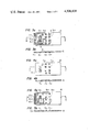
- FIG. 1a is a perspective view of the embodiment of the invention.
- FIG. 1b is a cross-sectional view taken along the lines A--A' of FIG. 1a;
- FIG. 2 is a top plan view of the embodiment of FIG. 1a illustrating various controlled areas in a pictorial diagram
- FIG. 3a is a bottom plan view of a first printed circuit board and FIG. 3b is a cross-sectional view taken along the lines B--B' of FIG. 3a;
- FIG. 4a is a top plan view of an insulative plate showing a plurality of elastic pressure responsive elements
- FIG. 4b is a cross-sectional view taken along the lines C--C' of FIG. 4a;
- FIG. 5a is a top plan view of a second printed circuit board, and FIG. 5b is a cross-sectional view taken along the lines D--D' of FIG. 5a;
- FIG. 6 is a cross-sectional view of the embodiment with an associated electrical circuit shown for explanation of the operation thereof;
- FIG. 7a is a top plan view of the first printed circuit board in a modified form
- FIG. 7b is a cross-sectional view taken along the lines E--E' of FIG. 7a;
- FIG. 8a is a top plan view of the second printed circuit board in a modified form
- FIG. 8b is a cross-sectional view taken along the lines F--F' of FIG. 8a;
- FIG. 9 is a cross-sectional view of the modification of the embodiment of FIG. 1a incorporating the modified printed circuit boards.
- reference numeral 1 is a film of a plastic material or its equivalents having the properties of flexibility and electrical insulation, on the surface of which is printed an illustration of a plan view of an automobile, for the purpose of disclosure, as shown in FIG. 2.
- reference numeral 12-1 is a trunk lid
- arrows 12-2 to 12-9 designate respectively the opening and closing directions of the vehicle's glass windows
- numeral 12-10 represents the fuel lid of the vehicle.
- the switching device of the invention includes a printed circuit board 2 formed of a flexible material, underside of which is printed as shown in FIGS. 3a and 3b a plurality of conductive elements or electrodes 3-1 to 3-10 (only 3-1 to 3-3 being shown for simplicity) in positions corresponding to the positions of the arrows 12-1 to 12-10 in the picture diagram of film 1, the electrodes being connected to the associated terminals 4-1 to 4-10 (only 4-1 to 4-3 being shown for simplicity) arranged on an edge of the printed circuit board 2.
- a slit 5 is formed in the circuit board 2 in such a manner as to partially surround each electrode 3 to prevent interference between adjacent electrodes to thereby permit each electrode to be pressure responsive only to the component of pressure acted thereon from directly above it.
- an insulative rigid plate 6 which, as shown in FIGS. 4a and 4b, is formed with a plurality of perforations in which are embedded elements 7-1 to 7-10 of rubber which normally exhibits nonconductivity but becomes conductive in response to a pressure exerted thereon.
- the elements 7-1 to 7-10 (only 7-1 to 7-3 being shown for simplicity) are positioned respectively to correspond to the positions of the electrodes 3-1 to 3-10 above.
- a printed circuit board 8 as illustrated in FIGS. 5a and 5b.
- a pattern of electrodes 9-1 to 9-10 (only 9-1 to 9-3 being shown for simplicity) similar to that shown in FIG. 3a and positioned to correspond to the positions of the rubber elements 7-1 to 7-10 above and connected respectively to terminals 10-1 to 10-10 (only 10-1 to 10-3 being shown for simplicity) arranged on an edge of the board 8.
- the film 1 and plates 2, 6 and 8 are in stacked relation as shown in FIG. 1 so that the rubber elements 7 are sandwiched between the associated electrodes 3 and 9 and housed within a framed structure 11 having an opening through which the illustration film 1 is exposed to the outside.
- numerals 13 is a finger of the operator
- 14 is a relay
- 15, a power source and 16 the solenoid of a trunk lid opener of an automobile.
- the electrode 3-1 When the operator depresses the film 1 with his finger 13 on the position illustrating the trunk lid 12-1, the electrode 3-1 is flexed downward to apply pressure to the rubber element 7-1 below due to the flexibility of film 1 and board 2.
- the pressure responsive variable resistance rubber element 7-1 rapidly reduces its resistance from the normal value of several tens of megohms to a conductive value of several tens of ohms measured in the direction of application of the pressure, so that there is established a low impedance path between terminals 4-1 and 10-1 via electrodes 3-1, rubber element 7-1 and electrode 9-1. This completes a circuit for the relay 14 to close its contacts which in turn energize the solenoid 16 to thereby open the trunk lid.
- connection of power driven window openers or fuel lid opener to the associated terminals permits operation of such devices in response to a pressure applied to the illustration film 1.
- Other devices to be connected to the switching device of the invention may include an engine hood opener, an electrically driven mirror and a power driven antenna.
- the relay 14 may be dispensed with if the device to be controlled requires no more than several hundreds milliamperes, permitting such devices to be directly connected to the terminals 4 and 10.
- flip-flop circuits may be employed to provide various modes of switching operations such as a locked switch which closes in response to the application of a pressure and opens in response to the application of a subsequent pressure, or a switch which closes its contact for a preset interval.
- the interference preventive slits 5 may be eliminated if the electrodes are spaced apart a distance greater than 10 millimeters.
- the electrodes in pairs are in stacked relation and correspond in position to each of the illustrated operative portion 12 on film 1, the area required for each illustrated portion 12 can be held to a minimum, thereby increasing the number of illustrated areas and hence the number of devices to be controlled.
- FIGS. 7a to 8b A modification of the present invention is illustrated in FIGS. 7a to 8b, in which the printed circuit board 2 is not provided with the terminals 4-1 to 4-10 and each of the electrodes 9 of the printed circuit board 6 is divided into two separate segments a and b which are connected to the associated terminals 10-a and 10-b as shown in FIG. 8a. Therefore, upon the application of a pressure downward, the contact element 3-1, for example, applies a pressure to the associated rubber element 7-1 below it to establish a low impedance path across the electrodes 9-1a and 9-1b, thereby providing a short-circuit across the terminals 10-1a and 10-1b, as best illustrated in FIG. 9.
- the switching device of the invention allows the operator to quickly recognize the location and function of a desired operative element. Since the switching device can accommodate many switching contacts, the size of the device can be kept to a minimum, and because of its thin plate-like structure it can be mounted on any desired place such as on the instrument panel of a vehicle or on the front panel of an electrical appliance, thereby providing a considerable degree of freedom in selecting its location for mounting. Furthermore, the electrical circuit is established via pressure responsive variable resistance elements, the likelihood of contact failure is considerably reduced, and since the circuit is established in response to a feathery touch on the illustration film, the invention provides ease of operation.
Landscapes
- Push-Button Switches (AREA)
- Adjustable Resistors (AREA)
Abstract
A switching device comprises a flexible film of insulative material on which is printed a pictorial diagram or the like illustrating a plurality of controlled devices. A plurality of first conductive elements is arranged on a plane in contact with the illustration film and a plurality of second conductive elements is arranged on a second plane spaced from the first plane. In response to a pressure manually applied to the illustration film at a point corresponding to a desired controlled device, the first and second elements of the corresponding pair are brought into electrical contact to complete a circuit through a pair of terminals. Preferably, between each pair of corresponding first and second conductive elements is disposed an elastic element having resistance which varies from a non-conductive value to a conductive value in response to a pressure applied thereto.
Description
The present invention relates generally to pressure sensitive switches and in particular to such a switch having a plurality of pressure responsive contact elements arranged on the corresponding operative positions of controlled devices which are pictorially illustrated on the front face of the switch.
The recent general tendency is toward using a pictorial representation on the front contact face of a switch to designate its operating function, rather than literal representation. Conventional methods however employ standardized symbols or marks on individual switches, which sometimes causes confusion because the switches are not positionally related to the actual location of the associated device. This is particularly true to switches provided on the instrument panel of motor vehicles. For safety purposes, ease with which the switches are recognized and operated is very important.
The switching device of the invention comprises a film of insulative material on which is printed a pictorial diagram illustrating various controlled devices. A plurality of first conductive elements is arranged on a first plane in contact with the film in positions corresponding to the positions of the controlled devices illustrated on the diagram. A plurality of second conductive elements is arranged on a second plane spaced from the first plane in positions corresponding to the positions of the first conductive elements. Terminals are provided for connection to the controlled devices. Responsive to a pressure applied to the illustration film in the position of a desired controlled devices, a corresponding pair of the first and second conductive elements are brought into electrical contact to complete a circuit through a pair of terminals to the desired controlled device.
Preferably, a plurality of normally conductive elements formed of an elastic material is provided between the first and second planes in positions corresponding to the first and second conductive elements. This elastic material exhibits conductivity in response to the application of a pressure applied thereto. This prevents the generation of spark across the contacting faces of the first and second elements due to the absence of an air gap therebetween.
An object of the present invention is to provide a novel switch which minimizes the space required to arrange a plurality of switches.
Another object of the invention is to provide a switch which facilitates recognition of the controlled devices and provides ease of operation.
A further object of the invention is to provide a switch of a nonlocked type having a thickness small enough to permit installation on the surface of a wall.
The invention will be further described by way of example with reference to the accompanying drawings, in which:
FIG. 1a is a perspective view of the embodiment of the invention;
FIG. 1b is a cross-sectional view taken along the lines A--A' of FIG. 1a;
FIG. 2 is a top plan view of the embodiment of FIG. 1a illustrating various controlled areas in a pictorial diagram;
FIG. 3a is a bottom plan view of a first printed circuit board and FIG. 3b is a cross-sectional view taken along the lines B--B' of FIG. 3a;
FIG. 4a is a top plan view of an insulative plate showing a plurality of elastic pressure responsive elements, and FIG. 4b is a cross-sectional view taken along the lines C--C' of FIG. 4a;
FIG. 5a is a top plan view of a second printed circuit board, and FIG. 5b is a cross-sectional view taken along the lines D--D' of FIG. 5a;
FIG. 6 is a cross-sectional view of the embodiment with an associated electrical circuit shown for explanation of the operation thereof;
FIG. 7a is a top plan view of the first printed circuit board in a modified form, and FIG. 7b is a cross-sectional view taken along the lines E--E' of FIG. 7a;
FIG. 8a is a top plan view of the second printed circuit board in a modified form, and FIG. 8b is a cross-sectional view taken along the lines F--F' of FIG. 8a; and
FIG. 9 is a cross-sectional view of the modification of the embodiment of FIG. 1a incorporating the modified printed circuit boards.
In FIG. 1, reference numeral 1 is a film of a plastic material or its equivalents having the properties of flexibility and electrical insulation, on the surface of which is printed an illustration of a plan view of an automobile, for the purpose of disclosure, as shown in FIG. 2. In FIG. 2, reference numeral 12-1 is a trunk lid, arrows 12-2 to 12-9 designate respectively the opening and closing directions of the vehicle's glass windows, and numeral 12-10 represents the fuel lid of the vehicle.
The switching device of the invention includes a printed circuit board 2 formed of a flexible material, underside of which is printed as shown in FIGS. 3a and 3b a plurality of conductive elements or electrodes 3-1 to 3-10 (only 3-1 to 3-3 being shown for simplicity) in positions corresponding to the positions of the arrows 12-1 to 12-10 in the picture diagram of film 1, the electrodes being connected to the associated terminals 4-1 to 4-10 (only 4-1 to 4-3 being shown for simplicity) arranged on an edge of the printed circuit board 2. A slit 5 is formed in the circuit board 2 in such a manner as to partially surround each electrode 3 to prevent interference between adjacent electrodes to thereby permit each electrode to be pressure responsive only to the component of pressure acted thereon from directly above it.
Beneath the printed circuit board 2 is provided an insulative rigid plate 6 which, as shown in FIGS. 4a and 4b, is formed with a plurality of perforations in which are embedded elements 7-1 to 7-10 of rubber which normally exhibits nonconductivity but becomes conductive in response to a pressure exerted thereon. The elements 7-1 to 7-10 (only 7-1 to 7-3 being shown for simplicity) are positioned respectively to correspond to the positions of the electrodes 3-1 to 3-10 above.
Below the rubber-embedded board 6 is provided a printed circuit board 8 as illustrated in FIGS. 5a and 5b. On the upper surface of the board 8 is printed a pattern of electrodes 9-1 to 9-10 (only 9-1 to 9-3 being shown for simplicity) similar to that shown in FIG. 3a and positioned to correspond to the positions of the rubber elements 7-1 to 7-10 above and connected respectively to terminals 10-1 to 10-10 (only 10-1 to 10-3 being shown for simplicity) arranged on an edge of the board 8.
The film 1 and plates 2, 6 and 8 are in stacked relation as shown in FIG. 1 so that the rubber elements 7 are sandwiched between the associated electrodes 3 and 9 and housed within a framed structure 11 having an opening through which the illustration film 1 is exposed to the outside.
The operation of the embodiment of the invention will be best described with reference to FIG. 6 in which numerals 13 is a finger of the operator, 14 is a relay, 15, a power source, and 16, the solenoid of a trunk lid opener of an automobile.
When the operator depresses the film 1 with his finger 13 on the position illustrating the trunk lid 12-1, the electrode 3-1 is flexed downward to apply pressure to the rubber element 7-1 below due to the flexibility of film 1 and board 2.
The pressure responsive variable resistance rubber element 7-1 rapidly reduces its resistance from the normal value of several tens of megohms to a conductive value of several tens of ohms measured in the direction of application of the pressure, so that there is established a low impedance path between terminals 4-1 and 10-1 via electrodes 3-1, rubber element 7-1 and electrode 9-1. This completes a circuit for the relay 14 to close its contacts which in turn energize the solenoid 16 to thereby open the trunk lid.
In the same manner as described above, connection of power driven window openers or fuel lid opener to the associated terminals permits operation of such devices in response to a pressure applied to the illustration film 1. Other devices to be connected to the switching device of the invention may include an engine hood opener, an electrically driven mirror and a power driven antenna.
In the circuit of FIG. 6, the relay 14 may be dispensed with if the device to be controlled requires no more than several hundreds milliamperes, permitting such devices to be directly connected to the terminals 4 and 10. Furthermore, flip-flop circuits may be employed to provide various modes of switching operations such as a locked switch which closes in response to the application of a pressure and opens in response to the application of a subsequent pressure, or a switch which closes its contact for a preset interval.
The interference preventive slits 5 may be eliminated if the electrodes are spaced apart a distance greater than 10 millimeters.
Since the electrodes in pairs are in stacked relation and correspond in position to each of the illustrated operative portion 12 on film 1, the area required for each illustrated portion 12 can be held to a minimum, thereby increasing the number of illustrated areas and hence the number of devices to be controlled.
A modification of the present invention is illustrated in FIGS. 7a to 8b, in which the printed circuit board 2 is not provided with the terminals 4-1 to 4-10 and each of the electrodes 9 of the printed circuit board 6 is divided into two separate segments a and b which are connected to the associated terminals 10-a and 10-b as shown in FIG. 8a. Therefore, upon the application of a pressure downward, the contact element 3-1, for example, applies a pressure to the associated rubber element 7-1 below it to establish a low impedance path across the electrodes 9-1a and 9-1b, thereby providing a short-circuit across the terminals 10-1a and 10-1b, as best illustrated in FIG. 9.
Although the above description is concerned with an application to automotive vehicles, the present invention could equally be used in other applications such as electrical appliances and system control devices as well.
As described above, the switching device of the invention allows the operator to quickly recognize the location and function of a desired operative element. Since the switching device can accommodate many switching contacts, the size of the device can be kept to a minimum, and because of its thin plate-like structure it can be mounted on any desired place such as on the instrument panel of a vehicle or on the front panel of an electrical appliance, thereby providing a considerable degree of freedom in selecting its location for mounting. Furthermore, the electrical circuit is established via pressure responsive variable resistance elements, the likelihood of contact failure is considerably reduced, and since the circuit is established in response to a feathery touch on the illustration film, the invention provides ease of operation.
The foregoing description shows only preferred embodiments of the invention. Various modifications are possible to those skilled in the art without departing from the scope of the invention which is only limited by the appended claims. For example, as a substitute for the printed circuit boards, pieces of metal foil secured to an insulative flexible board or pieces of pressure responsive conductive rubber embedded in a sheet of nonconductive rubber such as silicone rubber similar to that shown in FIG. 4b but having a smaller thickness, could be used equally as well.
Claims (2)
1. A switching device comprising a diagram sheet member illustrating a plurality of remote-controlled elements, an insulating member having a plurality of openings therein corresponding to said illustrated controlled elements, first and second printed-circuit boards spaced apart by said insulating member, each of said printed-circuit boards comprising a plurality of electrical circuits each terminating at one end in a position corresponding to the location of a respective one of said illustrated remote-controlled elements to form a pair of electrical contacts in said position with a corresponding termination of the other printed-circuit board and terminating at the other end to form a pair of terminals with a corresponding termination of the other printed-circuit board for connection to an external circuit, and a plurality of resilient, flexible members each accommodated in a respective one of said openings and having a variable resistance from a nonconductive, high resistance value to a conductive, low resistance value in response to a pressure applied thereto, said first printed-circuit board being in contact with said diagram sheet member and having sufficient flexibility so as to allow said pressure responsive variable resistance member to vary in resistance from high to low values when said pressure is applied to said diagram sheet member for establishing a conductive path between said electrical contacts.
2. A switching device comprising a diagram sheet member illustrating a plurality of remote-controlled elements, an insulating member having a plurality of openings therein corresponding to said illustrated remote-controlled elements, first and second printed-circuit boards spaced apart by said insulating member, said first printed-circuit board including a plurality of electrical conductive areas corresponding to said illustrated controlled elements, and said second printed circuit-board including a plurality of electrical circuits in pairs, each pair of said circuits terminating at one end in a position corresponding to a respective one of said illustrated remote-controlled elements to form a pair of electrical contacts in said position and terminating at the other end to form a pair of terminals for connection to an external circuit, and a plurality of resilient, flexible members each accomodated in a respective one of said openings and having a variable resistance from a nonconductive, high resistance value to a conductive, low resistance value in response to a pressure applied thereto, one of said first and second printed-circuit boards being in contact with said diagram sheet member and having sufficient flexibility so as to allow said pressure responsive variable resistance member to vary its resistance from high to low values when said pressure is applied to said diagram sheet member for establishing a conductive path between said electrical contacts through the corresponding conductive area on said first printed-circuit board.
Applications Claiming Priority (4)
| Application Number | Priority Date | Filing Date | Title |
|---|---|---|---|
| JP53-68313 | 1978-06-08 | ||
| JP6831378A JPS54159677A (en) | 1978-06-08 | 1978-06-08 | Pictorial indication switch |
| JP6985078A JPS54161081A (en) | 1978-06-12 | 1978-06-12 | Pictorial indication switch |
| JP53-69850 | 1978-06-12 |
Publications (1)
| Publication Number | Publication Date |
|---|---|
| US4308439A true US4308439A (en) | 1981-12-29 |
Family
ID=26409530
Family Applications (1)
| Application Number | Title | Priority Date | Filing Date |
|---|---|---|---|
| US06/035,990 Expired - Lifetime US4308439A (en) | 1978-06-08 | 1979-05-04 | Switching device |
Country Status (5)
| Country | Link |
|---|---|
| US (1) | US4308439A (en) |
| DE (1) | DE2922276C2 (en) |
| FR (1) | FR2428315A1 (en) |
| GB (1) | GB2023935B (en) |
| IT (1) | IT1116244B (en) |
Cited By (30)
| Publication number | Priority date | Publication date | Assignee | Title |
|---|---|---|---|---|
| FR2465306A1 (en) * | 1979-09-14 | 1981-03-20 | Nissan Motor | DUAL-ROLE DEVICE FOR CONTROLLING CIRCUITS AND DISPLAYING FUNCTIONS AT THE SAME TIME |
| US4362954A (en) * | 1981-09-25 | 1982-12-07 | The Maytag Company | Power-up control for microprocessor based appliance |
| US4368369A (en) * | 1980-03-14 | 1983-01-11 | Citizen Watch Co., Ltd. | Electrical switch |
| US4640994A (en) * | 1983-01-24 | 1987-02-03 | Sharp Kabushiki Kaisha | Electronic apparatus with a flat panel keyboard unit |
| US4691116A (en) * | 1984-08-07 | 1987-09-01 | Omron Tateisi Electronics Co. | Switch control device for motor vehicle |
| US4701629A (en) * | 1985-04-10 | 1987-10-20 | Citroen Maxime H | Switch control unit for motor vehicle |
| US4791252A (en) * | 1985-08-30 | 1988-12-13 | Vdo Adolf Schindling Ag | Touch panel switch operating arrangement |
| US4900946A (en) * | 1988-06-03 | 1990-02-13 | Navistar International Transportation Corp. | Multi-function switch for automotive vehicles |
| US4972051A (en) * | 1989-08-07 | 1990-11-20 | General Electric Company | Switch for two-way hand-held transceiver |
| US5332877A (en) * | 1989-06-30 | 1994-07-26 | Mitsubishi Denki Kabushiki Kaisha | Pictorial symbol switch |
| WO1995020233A1 (en) * | 1994-01-21 | 1995-07-27 | Davidson Textron Inc. | A horn actuator incorporating a transducer in a steering wheel |
| US5448028A (en) * | 1993-12-10 | 1995-09-05 | Davidson Textron, Inc. | Armrest electrical switch arrangement with soft interior trim panel |
| US5463258A (en) * | 1992-04-29 | 1995-10-31 | Davidson Textron Inc. | Horn actuator incorporating a transducer in a steering wheel |
| US5796059A (en) * | 1996-03-19 | 1998-08-18 | Boon; Stephen W. | Pressure-sensitive switch apparatus |
| US5861589A (en) * | 1996-06-14 | 1999-01-19 | Alps Electric Co., Ltd. | Vehicle air-conditioning control switch |
| US5990799A (en) * | 1998-10-06 | 1999-11-23 | Boon; Stephen W. | Chair occupancy monitoring device |
| FR2820819A1 (en) * | 2001-02-14 | 2002-08-16 | Cera | Flexible surface indentation detector e.g. for vehicle airbag system has compressible composition body and electrical resistance measuring device |
| FR2829522A1 (en) * | 2001-09-07 | 2003-03-14 | Siemens Automotive Sa | Automated electric window operator controlling device for vehicles, has control unit operating in conductive and resistive zones to react to both push and movement of finger |
| WO2004112068A1 (en) * | 2003-06-12 | 2004-12-23 | Bayerische Motoren Werke Aktiengesellschaft | Operating element |
| US6840339B1 (en) * | 1997-07-30 | 2005-01-11 | Still & Saxby S.A.R.L. | Towbar head for a towbar-guided industrial truck |
| US20050006213A1 (en) * | 2003-05-07 | 2005-01-13 | Harry Engelmann | Contact switching arrangement |
| US20060131159A1 (en) * | 2004-12-17 | 2006-06-22 | Diehl Ako Stiftung & Co., Kg | Capacitive touch switch |
| EP2015329A1 (en) * | 2007-07-09 | 2009-01-14 | Polymatech Co., Ltd. | Key sheet |
| US20090125195A1 (en) * | 2007-11-12 | 2009-05-14 | Ford Global Technologies, Llc | Operator control unit for devices in a motor vehicle |
| CN100529518C (en) * | 2006-09-14 | 2009-08-19 | 株式会社东海理化电机制作所 | Operation device |
| EP1570500B1 (en) * | 2002-12-09 | 2011-05-11 | Iee International Electronics & Engineering S.A. | Foil-type switching element with multi-layered carrier foil |
| US20110182456A1 (en) * | 2010-01-25 | 2011-07-28 | Hiroshi Akino | Boundary Microphone |
| US20160379772A1 (en) * | 2013-12-05 | 2016-12-29 | Fm Marketing Gmbh | Keyboard comprising multiple stabilized tile-shaped keys |
| RU2681204C2 (en) * | 2016-09-20 | 2019-03-05 | Общество с ограниченной ответственностью "Тонкопленочные элементы" | Switching device with light beam indication |
| RU2716841C2 (en) * | 2015-09-02 | 2020-03-17 | Конинклейке Филипс Н.В. | Switch based on electroactive or photoactive polymer |
Families Citing this family (8)
| Publication number | Priority date | Publication date | Assignee | Title |
|---|---|---|---|---|
| DE3031484A1 (en) * | 1980-08-21 | 1982-11-04 | Grundig Emv | Snap action push button switch for printed circuit - applies pressure to resilient film with conductive coating in region of contacts |
| DE3135427C2 (en) * | 1981-09-08 | 1985-07-18 | Telefunken electronic GmbH, 7100 Heilbronn | Push button switch |
| JPS59127328A (en) * | 1982-12-30 | 1984-07-23 | 日本メクトロン株式会社 | Keyboard switch |
| JPS60158342U (en) * | 1984-03-29 | 1985-10-22 | シャープ株式会社 | remote control transmitter |
| IT207494Z2 (en) * | 1985-10-03 | 1988-01-25 | Cavis Cavetti Isolati Spa | SWITCH STRUCTURE, PARTICULARLY DESIGNED FOR ELECTRIC WINDOWS OF MOTOR VEHICLES. |
| IT207493Z2 (en) * | 1985-10-03 | 1988-01-25 | Cavis Cavetti Isolati Spa | PUSH-BUTTON PANEL FOR AN AUTOMATIC AND MANUALLY OPERATED WINDOW REGULATOR, PARTICULARLY DESIGNED TO BE MOUNTED ON MOTOR VEHICLES. |
| IT207496Z2 (en) * | 1985-10-03 | 1988-01-25 | Cavis Cavetti Isolti S P A | SWITCH STRUCTURE, PARTICULARLY DESIGNED FOR ELECTRIC WINDOWS OF MOTOR VEHICLES. |
| GB2428770A (en) | 2005-07-25 | 2007-02-07 | Cnh Oesterreich Gmbh | Control panel with controls located on a visual representation of a machine |
Citations (7)
| Publication number | Priority date | Publication date | Assignee | Title |
|---|---|---|---|---|
| GB722035A (en) * | 1952-02-21 | 1955-01-19 | Gen Electric Co Ltd | Improvements in or relating to mimic diagrams for electrical networks or remote control systems |
| US3654407A (en) * | 1970-06-08 | 1972-04-04 | Sylvania Electric Prod | Compression switch |
| GB1298089A (en) * | 1969-02-24 | 1972-11-29 | William Barber Sudduth | Electric switch made of conducting elastomer |
| US3830991A (en) * | 1973-07-24 | 1974-08-20 | Essex International Inc | Pressure sensitive mat switch construction |
| US3859485A (en) * | 1973-02-26 | 1975-01-07 | Essex International Inc | Occupant sensor seat switch |
| DE2747425A1 (en) * | 1976-10-22 | 1978-04-27 | Bowmar Instrument Corp | FLAT SWITCH PANEL STRUCTURE |
| US4128744A (en) * | 1977-02-22 | 1978-12-05 | Chomerics, Inc. | Keyboard with concave and convex domes |
Family Cites Families (3)
| Publication number | Priority date | Publication date | Assignee | Title |
|---|---|---|---|---|
| DE2338746C2 (en) * | 1973-07-31 | 1982-10-21 | Licentia Patent-Verwaltungs-Gmbh, 6000 Frankfurt | Push button switch |
| US3860771A (en) * | 1973-10-29 | 1975-01-14 | Chomerics Inc | Keyboard switch assembly with dome shaped actuator having associated underlying contactor means |
| NL7606899A (en) * | 1976-06-24 | 1977-12-28 | Optosche Ind De Oude Delft Nv | OPTO-ELECTRICAL DETECTION SYSTEM. |
-
1979
- 1979-04-20 GB GB7913813A patent/GB2023935B/en not_active Expired
- 1979-05-04 US US06/035,990 patent/US4308439A/en not_active Expired - Lifetime
- 1979-05-17 FR FR7912554A patent/FR2428315A1/en active Granted
- 1979-05-31 DE DE2922276A patent/DE2922276C2/en not_active Expired
- 1979-06-06 IT IT49327/79A patent/IT1116244B/en active
Patent Citations (8)
| Publication number | Priority date | Publication date | Assignee | Title |
|---|---|---|---|---|
| GB722035A (en) * | 1952-02-21 | 1955-01-19 | Gen Electric Co Ltd | Improvements in or relating to mimic diagrams for electrical networks or remote control systems |
| GB1298089A (en) * | 1969-02-24 | 1972-11-29 | William Barber Sudduth | Electric switch made of conducting elastomer |
| US3654407A (en) * | 1970-06-08 | 1972-04-04 | Sylvania Electric Prod | Compression switch |
| US3859485A (en) * | 1973-02-26 | 1975-01-07 | Essex International Inc | Occupant sensor seat switch |
| US3830991A (en) * | 1973-07-24 | 1974-08-20 | Essex International Inc | Pressure sensitive mat switch construction |
| GB1454805A (en) * | 1973-07-24 | 1976-11-03 | Essex International Inc | Pressure sensitive switch construction |
| DE2747425A1 (en) * | 1976-10-22 | 1978-04-27 | Bowmar Instrument Corp | FLAT SWITCH PANEL STRUCTURE |
| US4128744A (en) * | 1977-02-22 | 1978-12-05 | Chomerics, Inc. | Keyboard with concave and convex domes |
Cited By (41)
| Publication number | Priority date | Publication date | Assignee | Title |
|---|---|---|---|---|
| FR2465306A1 (en) * | 1979-09-14 | 1981-03-20 | Nissan Motor | DUAL-ROLE DEVICE FOR CONTROLLING CIRCUITS AND DISPLAYING FUNCTIONS AT THE SAME TIME |
| US4368369A (en) * | 1980-03-14 | 1983-01-11 | Citizen Watch Co., Ltd. | Electrical switch |
| US4362954A (en) * | 1981-09-25 | 1982-12-07 | The Maytag Company | Power-up control for microprocessor based appliance |
| US4640994A (en) * | 1983-01-24 | 1987-02-03 | Sharp Kabushiki Kaisha | Electronic apparatus with a flat panel keyboard unit |
| US4691116A (en) * | 1984-08-07 | 1987-09-01 | Omron Tateisi Electronics Co. | Switch control device for motor vehicle |
| US4705959A (en) * | 1984-08-07 | 1987-11-10 | Omron Tateisi Electronics Co. | Switch control device for motor vehicle |
| US4701629A (en) * | 1985-04-10 | 1987-10-20 | Citroen Maxime H | Switch control unit for motor vehicle |
| US4791252A (en) * | 1985-08-30 | 1988-12-13 | Vdo Adolf Schindling Ag | Touch panel switch operating arrangement |
| US4900946A (en) * | 1988-06-03 | 1990-02-13 | Navistar International Transportation Corp. | Multi-function switch for automotive vehicles |
| US5332877A (en) * | 1989-06-30 | 1994-07-26 | Mitsubishi Denki Kabushiki Kaisha | Pictorial symbol switch |
| US4972051A (en) * | 1989-08-07 | 1990-11-20 | General Electric Company | Switch for two-way hand-held transceiver |
| US5463258A (en) * | 1992-04-29 | 1995-10-31 | Davidson Textron Inc. | Horn actuator incorporating a transducer in a steering wheel |
| US5539259A (en) * | 1992-04-29 | 1996-07-23 | Davidson Textron, Inc. | Horn actuator incorporating a transducer in a steering wheel |
| US5448028A (en) * | 1993-12-10 | 1995-09-05 | Davidson Textron, Inc. | Armrest electrical switch arrangement with soft interior trim panel |
| WO1995020233A1 (en) * | 1994-01-21 | 1995-07-27 | Davidson Textron Inc. | A horn actuator incorporating a transducer in a steering wheel |
| US5796059A (en) * | 1996-03-19 | 1998-08-18 | Boon; Stephen W. | Pressure-sensitive switch apparatus |
| US5861589A (en) * | 1996-06-14 | 1999-01-19 | Alps Electric Co., Ltd. | Vehicle air-conditioning control switch |
| US6840339B1 (en) * | 1997-07-30 | 2005-01-11 | Still & Saxby S.A.R.L. | Towbar head for a towbar-guided industrial truck |
| US5990799A (en) * | 1998-10-06 | 1999-11-23 | Boon; Stephen W. | Chair occupancy monitoring device |
| FR2820819A1 (en) * | 2001-02-14 | 2002-08-16 | Cera | Flexible surface indentation detector e.g. for vehicle airbag system has compressible composition body and electrical resistance measuring device |
| US6657140B2 (en) | 2001-09-07 | 2003-12-02 | Siemens Vdo Automotive | System for controlling a window operator |
| FR2829522A1 (en) * | 2001-09-07 | 2003-03-14 | Siemens Automotive Sa | Automated electric window operator controlling device for vehicles, has control unit operating in conductive and resistive zones to react to both push and movement of finger |
| EP1570500B1 (en) * | 2002-12-09 | 2011-05-11 | Iee International Electronics & Engineering S.A. | Foil-type switching element with multi-layered carrier foil |
| US20050006213A1 (en) * | 2003-05-07 | 2005-01-13 | Harry Engelmann | Contact switching arrangement |
| US6958459B2 (en) * | 2003-05-07 | 2005-10-25 | Schott Ag | Contact switching arrangement |
| WO2004112068A1 (en) * | 2003-06-12 | 2004-12-23 | Bayerische Motoren Werke Aktiengesellschaft | Operating element |
| US7638719B2 (en) | 2003-06-12 | 2009-12-29 | Bayerische Motoren Werke Aktiengesellschaft | Operating element |
| US20060144680A1 (en) * | 2003-06-12 | 2006-07-06 | Bayerische Motoren Werke Aktiengesellschaft | Operating element |
| KR100808745B1 (en) | 2003-06-12 | 2008-03-03 | 바이에리셰 모토렌 베르케 악티엔게젤샤프트 | Operating element |
| US7232973B2 (en) * | 2004-12-17 | 2007-06-19 | Diehl Ako Stiftung & Co. Kg | Capacitive touch switch |
| US20060131159A1 (en) * | 2004-12-17 | 2006-06-22 | Diehl Ako Stiftung & Co., Kg | Capacitive touch switch |
| CN100529518C (en) * | 2006-09-14 | 2009-08-19 | 株式会社东海理化电机制作所 | Operation device |
| US20090014304A1 (en) * | 2007-07-09 | 2009-01-15 | Polymatech Co., Ltd. | Key sheet |
| EP2015329A1 (en) * | 2007-07-09 | 2009-01-14 | Polymatech Co., Ltd. | Key sheet |
| US20090125195A1 (en) * | 2007-11-12 | 2009-05-14 | Ford Global Technologies, Llc | Operator control unit for devices in a motor vehicle |
| US8103405B2 (en) * | 2007-11-12 | 2012-01-24 | Ford Global Technologies, Llc | Operator control unit for devices in a motor vehicle |
| US20110182456A1 (en) * | 2010-01-25 | 2011-07-28 | Hiroshi Akino | Boundary Microphone |
| US20160379772A1 (en) * | 2013-12-05 | 2016-12-29 | Fm Marketing Gmbh | Keyboard comprising multiple stabilized tile-shaped keys |
| US9831051B2 (en) * | 2013-12-05 | 2017-11-28 | Fm Marketing Gmbh | Keyboard comprising multiple stabilized tile-shaped keys |
| RU2716841C2 (en) * | 2015-09-02 | 2020-03-17 | Конинклейке Филипс Н.В. | Switch based on electroactive or photoactive polymer |
| RU2681204C2 (en) * | 2016-09-20 | 2019-03-05 | Общество с ограниченной ответственностью "Тонкопленочные элементы" | Switching device with light beam indication |
Also Published As
| Publication number | Publication date |
|---|---|
| DE2922276A1 (en) | 1979-12-13 |
| FR2428315B1 (en) | 1981-12-24 |
| GB2023935B (en) | 1982-08-25 |
| IT7949327A0 (en) | 1979-06-06 |
| GB2023935A (en) | 1980-01-03 |
| DE2922276C2 (en) | 1983-06-01 |
| IT1116244B (en) | 1986-02-10 |
| FR2428315A1 (en) | 1980-01-04 |
Similar Documents
| Publication | Publication Date | Title |
|---|---|---|
| US4308439A (en) | Switching device | |
| EP0143734B1 (en) | Pressure sensitive signal generator assembly | |
| US5610380A (en) | Touch responsive control panel | |
| US5675319A (en) | Tamper detection device | |
| US4771139A (en) | Keyboard with metal cover and improved switches | |
| US4290052A (en) | Capacitive touch entry apparatus having high degree of personal safety | |
| US4360722A (en) | Designation cap actuator assembly | |
| US4376879A (en) | Button-less push switch boards | |
| US4334134A (en) | Identification cap actuator assembly | |
| US4228330A (en) | Touch panel mechanism | |
| KR860004370A (en) | IC card | |
| US4611261A (en) | Electronic equipment | |
| US4409450A (en) | Double pole membrane switch having preferred sequence closing feature | |
| TW359862B (en) | PTC conductive polymer protection device for surface mounting on a printed circuit board | |
| JPH02312174A (en) | Flexible circuit conneting deuice | |
| US4414452A (en) | Means for attaching auxiliary devices to a membrane switch | |
| US4796007A (en) | Micro-motion keyboard | |
| US4675787A (en) | Thin electronic apparatus | |
| JPS587556Y2 (en) | Picture display switch | |
| JPH0235478B2 (en) | ||
| EP0854667B1 (en) | Electronic control module | |
| US5493082A (en) | Elastomeric switch for electronic devices | |
| US4012710A (en) | Multiple output potentiometer network | |
| US4385213A (en) | Switch and component attachment to flexible printed circuitry | |
| US5293017A (en) | Right angle elastomeric control switch |
Legal Events
| Date | Code | Title | Description |
|---|---|---|---|
| STCF | Information on status: patent grant |
Free format text: PATENTED CASE |