US4323312A - Fluidized bed apparatus - Google Patents

Fluidized bed apparatus Download PDF

Info

Publication number
US4323312A
US4323312A US06/154,682 US15468280A US4323312A US 4323312 A US4323312 A US 4323312A US 15468280 A US15468280 A US 15468280A US 4323312 A US4323312 A US 4323312A
Authority
US
United States
Prior art keywords
rotor disc
fluidized bed
vessel
bed apparatus
further characterized
Prior art date
Legal status (The legal status is an assumption and is not a legal conclusion. Google has not performed a legal analysis and makes no representation as to the accuracy of the status listed.)
Expired - Lifetime
Application number
US06/154,682
Inventor
Werner Glatt
Kurt Bauer
Current Assignee (The listed assignees may be inaccurate. Google has not performed a legal analysis and makes no representation or warranty as to the accuracy of the list.)
WARNER GLATT
WERNER GLATT GmbH
Original Assignee
Werner Glatt
Kurt Bauer
Priority date (The priority date is an assumption and is not a legal conclusion. Google has not performed a legal analysis and makes no representation as to the accuracy of the date listed.)
Filing date
Publication date
Priority claimed from DE19772738485 external-priority patent/DE2738485A1/en
Priority claimed from DE19782805397 external-priority patent/DE2805397C3/en
Priority claimed from DE19803005770 external-priority patent/DE3005770A1/en
Application filed by Werner Glatt, Kurt Bauer filed Critical Werner Glatt
Application granted granted Critical
Publication of US4323312A publication Critical patent/US4323312A/en
Assigned to WARNER GLATT reassignment WARNER GLATT ASSIGNMENT OF ASSIGNORS INTEREST. Assignors: BAUER, KURT
Assigned to WERNER GLATT reassignment WERNER GLATT ASSIGNMENT OF ASSIGNORS INTEREST. Assignors: BAUER, KURT
Anticipated expiration legal-status Critical
Expired - Lifetime legal-status Critical Current

Links

Images

Classifications

    • BPERFORMING OPERATIONS; TRANSPORTING
    • B01PHYSICAL OR CHEMICAL PROCESSES OR APPARATUS IN GENERAL
    • B01JCHEMICAL OR PHYSICAL PROCESSES, e.g. CATALYSIS OR COLLOID CHEMISTRY; THEIR RELEVANT APPARATUS
    • B01J8/00Chemical or physical processes in general, conducted in the presence of fluids and solid particles; Apparatus for such processes
    • B01J8/18Chemical or physical processes in general, conducted in the presence of fluids and solid particles; Apparatus for such processes with fluidised particles
    • B01J8/24Chemical or physical processes in general, conducted in the presence of fluids and solid particles; Apparatus for such processes with fluidised particles according to "fluidised-bed" technique
    • B01J8/38Chemical or physical processes in general, conducted in the presence of fluids and solid particles; Apparatus for such processes with fluidised particles according to "fluidised-bed" technique with fluidised bed containing a rotatable device or being subject to rotation or to a circulatory movement, i.e. leaving a vessel and subsequently re-entering it
    • BPERFORMING OPERATIONS; TRANSPORTING
    • B01PHYSICAL OR CHEMICAL PROCESSES OR APPARATUS IN GENERAL
    • B01JCHEMICAL OR PHYSICAL PROCESSES, e.g. CATALYSIS OR COLLOID CHEMISTRY; THEIR RELEVANT APPARATUS
    • B01J2/00Processes or devices for granulating materials, e.g. fertilisers in general; Rendering particulate materials free flowing in general, e.g. making them hydrophobic
    • B01J2/16Processes or devices for granulating materials, e.g. fertilisers in general; Rendering particulate materials free flowing in general, e.g. making them hydrophobic by suspending the powder material in a gas, e.g. in fluidised beds or as a falling curtain
    • BPERFORMING OPERATIONS; TRANSPORTING
    • B01PHYSICAL OR CHEMICAL PROCESSES OR APPARATUS IN GENERAL
    • B01JCHEMICAL OR PHYSICAL PROCESSES, e.g. CATALYSIS OR COLLOID CHEMISTRY; THEIR RELEVANT APPARATUS
    • B01J8/00Chemical or physical processes in general, conducted in the presence of fluids and solid particles; Apparatus for such processes
    • B01J8/005Separating solid material from the gas/liquid stream
    • B01J8/006Separating solid material from the gas/liquid stream by filtration
    • BPERFORMING OPERATIONS; TRANSPORTING
    • B01PHYSICAL OR CHEMICAL PROCESSES OR APPARATUS IN GENERAL
    • B01JCHEMICAL OR PHYSICAL PROCESSES, e.g. CATALYSIS OR COLLOID CHEMISTRY; THEIR RELEVANT APPARATUS
    • B01J2219/00Chemical, physical or physico-chemical processes in general; Their relevant apparatus
    • B01J2219/19Details relating to the geometry of the reactor
    • B01J2219/194Details relating to the geometry of the reactor round
    • B01J2219/1941Details relating to the geometry of the reactor round circular or disk-shaped
    • B01J2219/1946Details relating to the geometry of the reactor round circular or disk-shaped conical

Definitions

  • the present invention relates to a fluidized bed apparatus, comprising a fluidized bed vessel in which a substantially horizontal rotor disc is arranged above a perforated bottom or above an air chamber for rotary movement about an at least approximately vertical axis and for adjustment along said axis.
  • the adjustability in height of the rotor disc provides the opportunity to adapt the flow conditions in the fluidized bed vessel in simple manner to various granulating materials and the resulting different operating conditions, regardless of the quantity of circulating air or other gas.
  • the fluidized bed vessel is separated from the air chamber by a perforated bottom which prevents material to be granulated or already granulated from falling out of the fluidized bed vessel into the air chamber, irrespective of the position in height of the rotor disc, when the air or other gas stream from the air chamber into the fluidized bed vessel to produce the fluidized bed therein is interrupted, as may become necessary, for instance, for cleaning exhaust air filters disposed above the fluidized bed vessel.
  • the perforated bottom makes it difficult to clean the entire fluidized bed apparatus, as frequently required above all in pharmaceutical enterprises, all the more so as the space between the rotor disc and the perforated bottom is not readily accessible.
  • granulating materials may collect in the space between the rotor disc and the perforated bottom during interruptions of operation for the purpose of cleaning the filters, and they may cause uncontrollable flow conditions when the fluidized bed is set into motion again. They may even stick to the walls of the fluidized bed vessel so as to disturb the adjustability in height of the rotor disc.
  • an object of the present invention to improve the mixing effect in a fluidized bed apparatus such that the material will flow upwards at the outside and downwards at the inside.
  • the fluidized bed vessel is tapered upwardly. This causes the material which is propelled radially outwardly by the rotor disc and then flows upwardly along the inner wall of the fluidized bed vessel to be gradually deflected radially inwardly away from the inner wall so that it will finally flow downwardly in the area of the axis of the fluidized bed vessel to regain the sphere of influence of the rotor disc.
  • the advantages of the invention thus reside in the fact that an essential improvement of the mixing grade in fluidized bed apparatus can be achieved in simple manner. This improvement is of great interest for fluidized bed mixers, dryers, reactors, and granulators alike. The invention has proved especially successful in the preparation of pharmaceutical granulates.
  • the rotor disc forming a flat cone and possibly having a central cone to facilitate the gliding of material off the central area of the rotor disc. Also, the rotor disc covers at least the central part of the perforated bottom thereby largely preventing the fluidized bed from getting under the influence of a strong upwardly directed air current in areas which are remote from the inner wall of the fluidized bed vessel.
  • the rotor disc may be perforated because the gas which passes in upward direction through the rotor disc is deflected radially outwardly under any circumstances if the speed of rotation of the rotor disc is sufficiently high.
  • the deflecting action of the rotor disc on the fluidized bed can be reinforced by mounting attachments in the form of baffle plates or wings or blades on the upper surface of the rotor disc.
  • the annular gap between the rotor disc and the inner wall of the fluidized bed vessel has a decisive importance on the air velocity in the entire fluidized bed vessel, the extent of which depends upon whether or not and to what extent the rotor disc is perforated.
  • the air velocity in turn is a critical factor in the process and must be adjusted to the optimum value in correspondence with the respective flow properties of the material (diameter and weight of the granulated material).
  • the tapering of the fluidized bed vessel affords the opportunity to improve the fluidized bed apparatus in accordance with the invention such that the flow conditions in the apparatus can be adjusted in a simple manner to different kinds of granulated material, irrespective of the quantity of circulating air or other gas.
  • the rotor disc is designed for adjustment in height in the lower conical part of the vessel.
  • the gap between the inner wall of the vessel and the outer edge of the rotor disc then can be reduced by raising the rotor disc.
  • the air velocity can be increased for a constant amount of air.
  • even a reduction of the air rate is possible and yet, the air velocity can be increased by simultaneous narrowing of the gap.
  • the adjustability in height of the rotor disc thus provides the advantage of always obtaining optimum adaptation of the fluidized bed apparatus to the flow characteristics of the granules. This makes it possible to establish optimum operating conditions for any specific product even by adjustment during operation with a view to the best possible quality of the product.
  • annular seat for the rotor disc is formed in the area of the lower end of the fluidized bed vessel, said rotor disc abutting against the seat in the one end position of its axial adjustment in the manner of a valve body, closing the air chamber toward the top.
  • the rotor disc comprises a sealing cord or sealing ledge secured to the edge of the disc.
  • FIG. 1 is a vertical sectional elevation of a fluidized bed apparatus equipped with a perforated rotor disc
  • FIGS. 2a to 2c are vertical sectional elevations of three variants of a rotor disc and an upwardly tapering fluidized bed vessel,
  • FIG. 3 is a vertical axial sectional elevation of a further embodiment of a fluidized bed apparatus with a fluidized bed vessel which narrows frustoconically in its lower portion and widens frustoconically in its upper portion, and
  • FIG. 4 is also a vertical axial sectional elevation of still another embodiment of a fluidized bed apparatus with a fluidized bed vessel which widens frustoconically upwardly in its lower portion and narrows frustoconically in its upper portion.
  • the fluidized bed apparatus as shown in FIG. 1 comprises a fluidized bed vessel 1 which is tapered conically in upward direction and followed by a cylindrical expansion zone 2.
  • a metering pump 3 supplies granulating liquid to the fluidized bed vessel 1 through a nozzle ring 4 between the vessel and the expansion zone 2.
  • the fluidized bed vessel 1 is defined by a perforated bottom 5 which may be set into oscillating movement by pneumatic pistons 6.
  • a horizontal perforated rotor disc 8 is spaced above the perforated bottom by from 0.5 to 20 mm and provided in the middle with a central core 9. The rotor disc 8 is adapted to be driven by a motor 10.
  • a turbine 11 serves to generate air circulation in the fluidized bed apparatus.
  • the air which the turbine 11 sucks from the expansion zone 2 passes through a round filter 12 which is provided with a tilting mechanism 13 for cleaning purposes.
  • a side channel 15 is disposed laterally of the fluidized bed vessel 1, the expansion zone 2, and the round filter 12. Exhaust air and fresh air are adjusted by an exhaust air regulating flap 16 and a fresh air regulator slide 17, respectively, at an air outlet and inlet opening 18.
  • the return air is recycled into the fluidized bed vessel 1 through a prefilter 19 and an air heater 20 in the side channel 15 and then through the perforated bottom 5.
  • the solid particles of the material contained in the fluidized bed vessel and to be treated, e.g. granulated therein, are conveyed in upward direction by the rising gas or air stream. Subsequently, they fall down inwardly onto the rotor disc 8 under gravity. The centrifugal force generated by the rotor disc 8 propels the solid particles again into the gas or air stream flowing from the bottom to the top. In this way, the uniform revolving or circulating solids movement of the fluidized bed is obtained, as shown in FIGS. 2a and 2b.
  • Conical shapes tapering upwardly have proved to be particularly favorable for shape of the fluidized bed vessel, as shown in FIGS. 2a, 2b, and 2c, because with the corresponding sections all of the material flowing in upward direction is deflected inwardly.
  • the Figures also indicate various embodiments of the rotor disc 8 (8', 8").
  • the rotor discs 8 and 8' are essentially flat, as shown in FIGS. 1, 2a and 2c.
  • the rotor disc 8" may also be inclined outwardly so that it forms a flat cone.
  • the maximum angle of inclination ⁇ may be 45°.
  • the angle of inclination is no more than 20°. It has proved to be advantageous to provide a central zone 9 in the middle of the rotor discs 8 and 8' and to have a slightly outwardly inclined surface of the rotor disc ( ⁇ 15°).
  • the base area of the central cone 9 normally has a diameter which corresponds to from 15 to 50%, preferably from 15 to 30% of the diameter of the rotor disc 8 or 8', while the height of the cone is between 5 and 50%, preferably from 10 to 30% based on the rotor disc diameter.
  • the surface proportion of the rotor disc should be from about 20 to 95%, preferably from 60 to 80% of the base area of the fluidized bed apparatus.
  • attachments 22 in the form of baffle plates or wings or blades may be mounted on the rotor discs 8 or 8', as illustrated in FIG. 2a.
  • the speed of rotation of the rotor disc 8 (8', 8") is to be from 20 to 1000, preferably from 40 to 150 r.p.m. so as to generate a sufficiently great centrifugal force.
  • the rotor disc 8' is supported for adjustment in height by means of an insertable shaft 23 supported through the intermission of an axial bearing 25 on a piston 24 of a pneumatic piston and cylinder unit to effect the raising and lowering.
  • the rotor disc 8 may also be supported on guide rollers or ball bearings 26 spaced from the shaft 23 and likewise adapted to be raised and lowered by pneumatic lifting devices. Piston 24 and also rollers or bearings 26 may be raised or lowered during operation and rotation of rotor disc 8' in order to determine and obtain optimum operating conditions. As shown in FIG.
  • the fluidized bed apparatus shown in FIG. 3 and FIG. 4 includes an air chamber 112 which is enclosed by a cylindrical wall 114 according to FIG. 3 and by a conically upwardly flaring wall 114' according to FIG. 4.
  • Three radial arms 116 carrying a bearing casing 118 are fixed at angular spacings of 120° to the wall 114, 114'.
  • a sleeve 122 is supported for rotation, yet axially fixed by two roller bearings 120 in the bearing casing 118.
  • a sprocket wheel 124 is attached to the sleeve 122, whereas it is a bevel gear 124' according to FIG. 4.
  • the sprocket wheel is adapted to be driven by way of a chain 126, preferably at infinitely variable speed, from an electric motor (not shown) secured to the wall 114.
  • the bevel gear 124' is adapted to be driven by a bevel pinion 128 and a shaft 132 supported in roller bearings 130 and arranged radially with respect to the wall 114', from an electric motor likewise not shown in FIG. 4.
  • a rotor shaft 134 is guided for axial displacement, i.e., in vertical direction in the sleeve 122.
  • a key 135 disposed as torque transmitting element between the sleeve 122 and the rotor shaft 134 warrants that the two can only rotate together.
  • the lower end of the rotor shaft 134 is supported in another axially loadable roller bearing pair 136 in a casing 138 which is supported by an affixed horizontal plate 140 on the circumferential surface of an eccentric disc 142 secured by a clamping sleeve 144 on a horizontal adjuster shaft 146.
  • a pair of pins 148 are secured to the plate 140 so as to straddle the shaft 146 like a fork, whereby plate 140 and casing 138 are prevented from rotating together with the rotor shaft 134.
  • the horizontal adjuster shaft 146 in turn is held axially fixed in bearing bushings 150 and 152 fixed to wall 114 or 114', respectively, diametrically opposite each other.
  • the fluidized bed apparatus is so designed that the adjuster shaft 146 is rotatable by an adjuster clamp handle 154 which is axially displaceably arranged at one end of the shaft projecting out of the bearing bushing 152 through the intermission of a friction disc 156.
  • a tensioning clamp handle 158 is provided to clamp the adjuster shaft 146 in a selected angle of rotation position.
  • a similar effect can be achieved with the fluidized bed apparatus according to FIG. 4 in that a gear 162 is secured on the adjuster shaft 146 and meshes with a pinion 164 on a countershaft 166 which in turn is supported in a bushing 168 fixed to the wall 114'.
  • a handwheel 170 is connected with the countershaft 166 for common rotation.
  • the countershaft 166 can be clamped in a selected angle of rotation position by means of a nut 172 threaded on the shaft and supported on the handwheel 170 through the intermission of cup springs 174. In this manner, the rotor shaft 134 may be retained in a selected elevation with the fluidized bed apparatus according to FIG. 2 as well.
  • a threaded pin 176 is formed at the upper end of the rotor shaft 134 to receive a rotor disc 178 or 178' which is clamped tight by a nut 180. Furthermore, a cone 182 is screwed on the threaded pin 176 to press with its basis on the rotor disc 178.
  • annular sealing cord 184 is fixed at the outer edge of the rotor disc 178 and embedded with approximately half its circular cross-section in an annular collar 186 of the rotor disc.
  • a flat annular sealing ledge 184' is fixed at the outer edge of the rotor disc 178', for instance, by gluing, according to FIG. 4.
  • annular seat 188 is provided around the rotor disc 178 or 178'. According to FIG. 3, it is formed at an independent, axially symmetrical structural element 190, screw connected with the wall 114, and tapers frustoconically in upward direction. According to FIG. 4, on the other hand, it is formed in the wall 114' itself and widens frustoconically in upward direction.
  • both embodiments include a frustoconical lower member 192 or 192' of a fluidized bed vessel 192, 194, or 192', 194' formed integrally or connected by flanges.
  • this lower member tapers upwardly, while it is widened upwardly in the embodiment according to FIG. 4.
  • An upper member 194, likewise of frustoconical shape, of the fluidized bed vessel 192, 194 is flanged to the lower member 192 and widens upwardly according to FIG. 3, while member 194' narrows upwardly according to FIG. 4.
  • the fluidized bed apparatus shown in FIG. 3 comprises a perforated bottom 196 below the rotor disc 178' as the upper limit of the air chamber 112 and clamped between an annular upper end face of the wall 114 and the annular structural member 190.
  • the fluidized bed apparatus according to FIG. 4 does not comprise such a perforated bottom so that the air chamber 112 can be closed at the top only by the rotor disc 178'.
  • the rotor disc 178 is shown in FIG. 3 in its upper end position in sealing engagement against seat 188 by means of its sealing cord 184.
  • the rotor disc 178 may be lowered more or less out of its upper end position until close to the perforated bottom 196 so that a more or less wide annular gap is formed between the outer edge of the rotor disc 178 and the seat 188.
  • the annular sealing lege 184' may be made of a yielding, low-friction material like polytetraflouroethylene and so dimensioned that it will engage the lower member 192' of the fluidized bed vessel 192', 194' even with the rotor disc 178' in its upper end position. Yet this engagement will be at such little pressure that the sealing ledge will act like a flap valve and permit air or other gas flow from the air chamber 112 into the fluidized bed vessel 192', 194' without giving any processed material contained in the fluidized bed vessel a chance to fall into the air chamber 112.

Abstract

Fluidized bed apparatus, comprising a fluidized bed vessel in which a substantially horizontal rotor disc is arranged above a perforated bottom or above an air chamber for rotary movement about an at least approximately vertical axis and for adjustment along said axis. The fluidized bed vessel is tapered upwardly, one portion inwardly and one outwardly to enhance the flow therein and the rotor disc forms a flat cone and the disc may have a central cone with the rotor disc covering at least the central part of the perforated bottom.

Description

BACKGROUND OF THE INVENTION
This application is a continuation-in-part application of the present inventors' application Ser. No. 936,955 entitled FLUIDIZED BED APPARATUS and filed Aug. 25, 1978, and now abandoned.
The present invention relates to a fluidized bed apparatus, comprising a fluidized bed vessel in which a substantially horizontal rotor disc is arranged above a perforated bottom or above an air chamber for rotary movement about an at least approximately vertical axis and for adjustment along said axis.
The adjustability in height of the rotor disc provides the opportunity to adapt the flow conditions in the fluidized bed vessel in simple manner to various granulating materials and the resulting different operating conditions, regardless of the quantity of circulating air or other gas.
In one embodiment, the fluidized bed vessel is separated from the air chamber by a perforated bottom which prevents material to be granulated or already granulated from falling out of the fluidized bed vessel into the air chamber, irrespective of the position in height of the rotor disc, when the air or other gas stream from the air chamber into the fluidized bed vessel to produce the fluidized bed therein is interrupted, as may become necessary, for instance, for cleaning exhaust air filters disposed above the fluidized bed vessel. Yet the perforated bottom, on the one hand, makes it difficult to clean the entire fluidized bed apparatus, as frequently required above all in pharmaceutical enterprises, all the more so as the space between the rotor disc and the perforated bottom is not readily accessible. Besides, granulating materials may collect in the space between the rotor disc and the perforated bottom during interruptions of operation for the purpose of cleaning the filters, and they may cause uncontrollable flow conditions when the fluidized bed is set into motion again. They may even stick to the walls of the fluidized bed vessel so as to disturb the adjustability in height of the rotor disc.
As is well known, the properties of thorough mixing and heat transfer in fluidized bed apparatus depend largely on the motion of the solids in addition to the formation and movement of bubbles in the fluidized or aerated bed.
Thorough mixing or the prevention of dissociation of the material to be reacted often present great problems, particularly so if the material to be reacted is of varying density and/or varying particle size and/or varying surface characteristics. Very often this is an annoying problem in the preparation of pharmaceutical granulates.
Attempts to solve these problems up to now provided for the use of different built-in structures or pneumatic mixing devices or swinging or oscillating perforated bottoms in fluidized bed reactors.
It has also been attempted to avoid the formation of channels (concentration of the material in narrow channels or tubes) by disposing a star agitator above the perforated bottom, thus improving the fluidized bed motion. However, the star agitator causes practically no centrifugal movement of the material. As with all the other apparatus of the kind known until the present time, the material essentially ascends in the middle and flows down on the outside. In some cases of application, in particular when spraying the material to obtain granulated material, this has the undesired consequence of moist material contacting the wall and easily sticking to the same.
SUMMARY OF THE INVENTION
It is, therefore, an object of the present invention to improve the mixing effect in a fluidized bed apparatus such that the material will flow upwards at the outside and downwards at the inside.
This object is met, in accordance with the invention, in that the fluidized bed vessel is tapered upwardly. This causes the material which is propelled radially outwardly by the rotor disc and then flows upwardly along the inner wall of the fluidized bed vessel to be gradually deflected radially inwardly away from the inner wall so that it will finally flow downwardly in the area of the axis of the fluidized bed vessel to regain the sphere of influence of the rotor disc. The advantages of the invention thus reside in the fact that an essential improvement of the mixing grade in fluidized bed apparatus can be achieved in simple manner. This improvement is of great interest for fluidized bed mixers, dryers, reactors, and granulators alike. The invention has proved especially successful in the preparation of pharmaceutical granulates.
Distance between the perforated bottom and the rotor disc allows the gas flowing upwardly through the perforated bottom to have a component of flow which is directed radially outwards. Flow is further enhanced by the rotor disc forming a flat cone and possibly having a central cone to facilitate the gliding of material off the central area of the rotor disc. Also, the rotor disc covers at least the central part of the perforated bottom thereby largely preventing the fluidized bed from getting under the influence of a strong upwardly directed air current in areas which are remote from the inner wall of the fluidized bed vessel.
In spite of the above, the rotor disc may be perforated because the gas which passes in upward direction through the rotor disc is deflected radially outwardly under any circumstances if the speed of rotation of the rotor disc is sufficiently high.
The deflecting action of the rotor disc on the fluidized bed can be reinforced by mounting attachments in the form of baffle plates or wings or blades on the upper surface of the rotor disc.
The annular gap between the rotor disc and the inner wall of the fluidized bed vessel has a decisive importance on the air velocity in the entire fluidized bed vessel, the extent of which depends upon whether or not and to what extent the rotor disc is perforated. The air velocity in turn is a critical factor in the process and must be adjusted to the optimum value in correspondence with the respective flow properties of the material (diameter and weight of the granulated material). The tapering of the fluidized bed vessel affords the opportunity to improve the fluidized bed apparatus in accordance with the invention such that the flow conditions in the apparatus can be adjusted in a simple manner to different kinds of granulated material, irrespective of the quantity of circulating air or other gas.
This additional advantage is obtained, in accordance with the invention, in that the rotor disc is designed for adjustment in height in the lower conical part of the vessel. The gap between the inner wall of the vessel and the outer edge of the rotor disc then can be reduced by raising the rotor disc. In this way, the air velocity can be increased for a constant amount of air. Furthermore, even a reduction of the air rate is possible and yet, the air velocity can be increased by simultaneous narrowing of the gap. The adjustability in height of the rotor disc thus provides the advantage of always obtaining optimum adaptation of the fluidized bed apparatus to the flow characteristics of the granules. This makes it possible to establish optimum operating conditions for any specific product even by adjustment during operation with a view to the best possible quality of the product.
It is, therefore, another object of the instant invention to develop a fluidized bed apparatus of the kind defined initially such that it will be easier to make it ready for operation again after shutdown.
This object is met, in accordance with the invention, in that an annular seat for the rotor disc is formed in the area of the lower end of the fluidized bed vessel, said rotor disc abutting against the seat in the one end position of its axial adjustment in the manner of a valve body, closing the air chamber toward the top.
Thus, it is possible to close the fluidized bed vessel absolutely tightly toward the bottom, either during filling of the fluidized bed vessel or for short interruptions of operation to clean filters, for instance, by vibration or for emptying the fluidized bed vessel upon completion of a granulating process. Positive pressure can be produced in the air chamber before an annular gap is opened once more between the seat and the rotor disc upon renewed start-up of the apparatus. Thus, it can be prevented positively at any operational condition that granulating material or the finished granules will fall from the fluidized bed vessel into the air chamber.
In particularly useful embodiments of the invention, the rotor disc comprises a sealing cord or sealing ledge secured to the edge of the disc.
BRIEF DESCRIPTION OF THE DRAWINGS
The invention will be described further, by way of example, with reference to the accompanying drawings, in which:
FIG. 1 is a vertical sectional elevation of a fluidized bed apparatus equipped with a perforated rotor disc,
FIGS. 2a to 2c are vertical sectional elevations of three variants of a rotor disc and an upwardly tapering fluidized bed vessel,
FIG. 3 is a vertical axial sectional elevation of a further embodiment of a fluidized bed apparatus with a fluidized bed vessel which narrows frustoconically in its lower portion and widens frustoconically in its upper portion, and
FIG. 4 is also a vertical axial sectional elevation of still another embodiment of a fluidized bed apparatus with a fluidized bed vessel which widens frustoconically upwardly in its lower portion and narrows frustoconically in its upper portion.
DESCRIPTION OF THE PREFERRED EMBODIMENTS
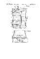
The fluidized bed apparatus as shown in FIG. 1 comprises a fluidized bed vessel 1 which is tapered conically in upward direction and followed by a cylindrical expansion zone 2. A metering pump 3 supplies granulating liquid to the fluidized bed vessel 1 through a nozzle ring 4 between the vessel and the expansion zone 2. At its underside, the fluidized bed vessel 1 is defined by a perforated bottom 5 which may be set into oscillating movement by pneumatic pistons 6. A horizontal perforated rotor disc 8 is spaced above the perforated bottom by from 0.5 to 20 mm and provided in the middle with a central core 9. The rotor disc 8 is adapted to be driven by a motor 10.
A turbine 11 serves to generate air circulation in the fluidized bed apparatus. The air which the turbine 11 sucks from the expansion zone 2 passes through a round filter 12 which is provided with a tilting mechanism 13 for cleaning purposes. A side channel 15 is disposed laterally of the fluidized bed vessel 1, the expansion zone 2, and the round filter 12. Exhaust air and fresh air are adjusted by an exhaust air regulating flap 16 and a fresh air regulator slide 17, respectively, at an air outlet and inlet opening 18. The return air is recycled into the fluidized bed vessel 1 through a prefilter 19 and an air heater 20 in the side channel 15 and then through the perforated bottom 5.
The solid particles of the material contained in the fluidized bed vessel and to be treated, e.g. granulated therein, are conveyed in upward direction by the rising gas or air stream. Subsequently, they fall down inwardly onto the rotor disc 8 under gravity. The centrifugal force generated by the rotor disc 8 propels the solid particles again into the gas or air stream flowing from the bottom to the top. In this way, the uniform revolving or circulating solids movement of the fluidized bed is obtained, as shown in FIGS. 2a and 2b.
Conical shapes tapering upwardly have proved to be particularly favorable for shape of the fluidized bed vessel, as shown in FIGS. 2a, 2b, and 2c, because with the corresponding sections all of the material flowing in upward direction is deflected inwardly.
The Figures also indicate various embodiments of the rotor disc 8 (8', 8"). In the most simple cases, the rotor discs 8 and 8' are essentially flat, as shown in FIGS. 1, 2a and 2c. However, as shown in FIG. 2b, the rotor disc 8" may also be inclined outwardly so that it forms a flat cone. The maximum angle of inclination α may be 45°. Preferably, however, the angle of inclination is no more than 20°. It has proved to be advantageous to provide a central zone 9 in the middle of the rotor discs 8 and 8' and to have a slightly outwardly inclined surface of the rotor disc (α≦15°). The base area of the central cone 9 normally has a diameter which corresponds to from 15 to 50%, preferably from 15 to 30% of the diameter of the rotor disc 8 or 8', while the height of the cone is between 5 and 50%, preferably from 10 to 30% based on the rotor disc diameter. The surface proportion of the rotor disc should be from about 20 to 95%, preferably from 60 to 80% of the base area of the fluidized bed apparatus.
It is the purpose of the perforations 21 in rotor disc 8, which may be gathered from the drawings, to let a certain proportion of the air or gas stream flow to the top also in the center of the fluidized bed vessel 1.
In special cases, attachments 22 in the form of baffle plates or wings or blades may be mounted on the rotor discs 8 or 8', as illustrated in FIG. 2a.
The speed of rotation of the rotor disc 8 (8', 8") is to be from 20 to 1000, preferably from 40 to 150 r.p.m. so as to generate a sufficiently great centrifugal force.
In the embodiment according to FIG. 2c, the rotor disc 8' is supported for adjustment in height by means of an insertable shaft 23 supported through the intermission of an axial bearing 25 on a piston 24 of a pneumatic piston and cylinder unit to effect the raising and lowering. The rotor disc 8 may also be supported on guide rollers or ball bearings 26 spaced from the shaft 23 and likewise adapted to be raised and lowered by pneumatic lifting devices. Piston 24 and also rollers or bearings 26 may be raised or lowered during operation and rotation of rotor disc 8' in order to determine and obtain optimum operating conditions. As shown in FIG. 2c, the gap d between the outer edge of the rotor disc and the inner wall of the fluidized bed vessel is narrowed as the rotor disc 8' is raised. This also holds true for rotor discs 8, 8' and 8" in FIGS. 1, 2a, and 2b, respectively.
The fluidized bed apparatus shown in FIG. 3 and FIG. 4 includes an air chamber 112 which is enclosed by a cylindrical wall 114 according to FIG. 3 and by a conically upwardly flaring wall 114' according to FIG. 4.
Three radial arms 116 carrying a bearing casing 118 are fixed at angular spacings of 120° to the wall 114, 114'. A sleeve 122 is supported for rotation, yet axially fixed by two roller bearings 120 in the bearing casing 118. According to FIG. 3, a sprocket wheel 124 is attached to the sleeve 122, whereas it is a bevel gear 124' according to FIG. 4. The sprocket wheel is adapted to be driven by way of a chain 126, preferably at infinitely variable speed, from an electric motor (not shown) secured to the wall 114. In corresponding manner, the bevel gear 124' is adapted to be driven by a bevel pinion 128 and a shaft 132 supported in roller bearings 130 and arranged radially with respect to the wall 114', from an electric motor likewise not shown in FIG. 4.
With both embodiments according to FIGS. 3 and 4, a rotor shaft 134 is guided for axial displacement, i.e., in vertical direction in the sleeve 122. A key 135 disposed as torque transmitting element between the sleeve 122 and the rotor shaft 134 warrants that the two can only rotate together. The lower end of the rotor shaft 134 is supported in another axially loadable roller bearing pair 136 in a casing 138 which is supported by an affixed horizontal plate 140 on the circumferential surface of an eccentric disc 142 secured by a clamping sleeve 144 on a horizontal adjuster shaft 146. A pair of pins 148 are secured to the plate 140 so as to straddle the shaft 146 like a fork, whereby plate 140 and casing 138 are prevented from rotating together with the rotor shaft 134. The horizontal adjuster shaft 146 in turn is held axially fixed in bearing bushings 150 and 152 fixed to wall 114 or 114', respectively, diametrically opposite each other.
The fluidized bed apparatus according to FIG. 3 is so designed that the adjuster shaft 146 is rotatable by an adjuster clamp handle 154 which is axially displaceably arranged at one end of the shaft projecting out of the bearing bushing 152 through the intermission of a friction disc 156. A tensioning clamp handle 158 is provided to clamp the adjuster shaft 146 in a selected angle of rotation position. There is a threaded connection between the tensioning clamp handle 158 and one end of the adjuster shaft, and the tensioning clamp handle 158 is supported at the end face of the adjuster clamp handle 154 remote from the first friction disc 156, through the intermission of a second friction disc 160. By rotating and subsequently clamping the adjuster shaft 146, the rotor shaft 134 can be adjusted in vertical direction and then kept at the desired level.
A similar effect can be achieved with the fluidized bed apparatus according to FIG. 4 in that a gear 162 is secured on the adjuster shaft 146 and meshes with a pinion 164 on a countershaft 166 which in turn is supported in a bushing 168 fixed to the wall 114'. A handwheel 170 is connected with the countershaft 166 for common rotation. The countershaft 166 can be clamped in a selected angle of rotation position by means of a nut 172 threaded on the shaft and supported on the handwheel 170 through the intermission of cup springs 174. In this manner, the rotor shaft 134 may be retained in a selected elevation with the fluidized bed apparatus according to FIG. 2 as well.
With both fluidized bed apparatus according to FIGS. 3 and 4, a threaded pin 176 is formed at the upper end of the rotor shaft 134 to receive a rotor disc 178 or 178' which is clamped tight by a nut 180. Furthermore, a cone 182 is screwed on the threaded pin 176 to press with its basis on the rotor disc 178.
According to FIG. 3, an annular sealing cord 184 is fixed at the outer edge of the rotor disc 178 and embedded with approximately half its circular cross-section in an annular collar 186 of the rotor disc. Instead of a sealing cord 184, a flat annular sealing ledge 184' is fixed at the outer edge of the rotor disc 178', for instance, by gluing, according to FIG. 4.
In both embodiments according to FIGS. 3 and 4, an annular seat 188 is provided around the rotor disc 178 or 178'. According to FIG. 3, it is formed at an independent, axially symmetrical structural element 190, screw connected with the wall 114, and tapers frustoconically in upward direction. According to FIG. 4, on the other hand, it is formed in the wall 114' itself and widens frustoconically in upward direction.
Above the annular seat 188, both embodiments include a frustoconical lower member 192 or 192' of a fluidized bed vessel 192, 194, or 192', 194' formed integrally or connected by flanges. In the case of the embodiment according to FIG. 3, this lower member tapers upwardly, while it is widened upwardly in the embodiment according to FIG. 4. An upper member 194, likewise of frustoconical shape, of the fluidized bed vessel 192, 194 is flanged to the lower member 192 and widens upwardly according to FIG. 3, while member 194' narrows upwardly according to FIG. 4.
The fluidized bed apparatus shown in FIG. 3 comprises a perforated bottom 196 below the rotor disc 178' as the upper limit of the air chamber 112 and clamped between an annular upper end face of the wall 114 and the annular structural member 190. The fluidized bed apparatus according to FIG. 4 does not comprise such a perforated bottom so that the air chamber 112 can be closed at the top only by the rotor disc 178'.
The rotor disc 178 is shown in FIG. 3 in its upper end position in sealing engagement against seat 188 by means of its sealing cord 184. By rotating the adjuster shaft 146, the rotor disc 178 may be lowered more or less out of its upper end position until close to the perforated bottom 196 so that a more or less wide annular gap is formed between the outer edge of the rotor disc 178 and the seat 188.
The opposite happens with the fluidized bed apparatus shown in FIG. 4: In its upper end position, shown in continuous lines, the rotor disc 178' leaves an annular gap 198 between itself and the lower member 192' of the fluidized bed vessel 192', 194'. From this upper end position, the rotor disc may be lowered into a lower end position in which it is indicated in discontinuous lines at the left of FIG. 4 and in which it closely abuts the seat 188 with its outer edge. According to FIG. 4, the annular sealing lege 184' may be made of a yielding, low-friction material like polytetraflouroethylene and so dimensioned that it will engage the lower member 192' of the fluidized bed vessel 192', 194' even with the rotor disc 178' in its upper end position. Yet this engagement will be at such little pressure that the sealing ledge will act like a flap valve and permit air or other gas flow from the air chamber 112 into the fluidized bed vessel 192', 194' without giving any processed material contained in the fluidized bed vessel a chance to fall into the air chamber 112. As the rotor disc 178' is lowered, the pressure increases under which the sealing ledge 184' abuts against the lower member 192' of the fluidized bed vessel until the rotor disc 178' rests firmly on the seat 188, thus interrupting any flow from the air chamber 112 into the fluidized bed vessel 192', 194'.
It will be obvious to those skilled in the art that various changes may be made without departing from the scope of the invention and the invention is not to be considered limited to what is shown in the drawings and described in the specification.

Claims (20)

What is claimed is:
1. A fluidized bed apparatus comprising
a fluidized bed vessel having walls tapered inwardly as it extends upwardly and having a perforated bottom,
a substantially horizontal rotor disc arranged above said bottom of said vessel,
said rotor disc being of smaller horizontal dimension than the corresponding horizontal dimension of said vessel and forming an annular gap between the circumferential edge of said rotor disc and the upwardly and inwardly tapered wall of said vessel,
means for adjusting the height of said rotor disc connected to said rotor disc and thereby changing the width of said annular gap,
means for rotating said rotor disc about an at least approximately vertical axis connected to said rotor disc,
means for moving a flow of air or other gas into said vessel through said bottom and through said annular gap around the periphery of said rotor disc,
means for releasing material to be treated into the moving gas forming a fluidized bed moved by said rotor disc and the moving gas passing through said annular gap,
whereby the velocity of the flow of gas through said annular gap is adjusted to the varying density, particle size, and surface characteristics of the material to be treated by varying the height of said rotor disc in relation to said walls of said vessel to decrease said gap and increase flow velocity and alternatively to increase said gap and decrease flow velocity.
2. The fluidized bed apparatus as claimed in claim 1, characterized in that the distance between said perforated bottom and said rotor disc is in the range from 0.5 to 20.0 mm.
3. The fluidized bed apparatus as claimed in claim 2, further characterized by
the base area of said rotor disc amounting to from 60 to 80% of the area of the bottom of said fluidized bed vessel.
4. The fluidized bed apparatus as claimed in claim 1, further characterized by
said rotor disc being a shallow cone having an angle of inclination not exceeding 45°.
5. The fluidized bed apparatus as claimed in claim 1, further characterized by
said rotor disc having a central cone,
said central cone having a base area diameter amounting to from 15 to 50% of the diameter of said rotor disc and a height amounting to from 5 to 50% of the diameter of said rotor disc.
6. The fluidized bed apparatus as claimed in claim 5, further characterized by
the base area of said rotor disc amounting to from 60 to 80% of the area of the bottom of said fluidized bed vessel.
7. The fluidized bed apparatus as claimed in claim 1, further characterized by
the base of said rotor disc amounting to from 60 to 80% of the area of the bottom of said fluidized bed vessel.
8. The fluidized bed apparatus as claimed in claim 1, further characterized by
attachment means to increase centrifugal and upward flow in the fluidized bed, attached on the upper side of said rotor disc.
9. The fluidized bed apparatus as claimed in claim 8, further characterized by
said attachment means being baffle plates.
10. The fluidized bed apparatus as claimed in claim 8, further characterized by
said attachment means being blades.
11. The fluidized bed apparatus as claimed in claim 1, further characterized by
said fluidized bed vessel including two sections disposed one above the other,
the lower of said sections together with said rotor disc defining said annular gap and being more tapered inwardly as it extends upwardly than the upper of said sections.
12. The fluidized bed apparatus as claimed in claim 1, further characterized by
said means for adjusting the height of said rotor disc including piston means attached to said rotor disc for vertical reciprocating motion.
13. The fluidized bed apparatus as claimed in claim 12, further characterized by
said means for adjusting the height of said rotor disc further including vertically adjustable guide means supporting the underside of said rotor disc.
14. The fluidized bed apparatus as claimed in claim 1, further characterized by
said source of air including
means to exhaust air from said fluidized bed vessel, and regulating means in the path of air exhausted from said vessel to regulate the amount of air entering from outside said vessel and passing through said perforated bottom with said air exhausted from said vessel.
15. The fluidized bed apparatus as claimed in claim 1, further characterized by
said means for adjusting the height of said rotor disc also being operable during rotation of said rotor disc.
16. A fluidized bed apparatus comprising
a fluidized bed vessel,
an annular seat formed in said vessel,
a substantially horizontal rotor disc arranged within said vessel,
said rotor disc forming an annular gap between the circumferential edge of said rotor disc and said annular seat,
means for adjusting the height of said rotor disc connected to said rotor disc and thereby changing the width of said annular gap,
means for rotating said rotor disc about an at least approximately vertical axis connected to said rotor disc,
means for moving a flow of air or other gas into said vessel beneath said rotor disc and through said annular gap around the periphery of said rotor disc,
means for releasing material to be treated into said vessel above said rotor disc,
said material forming a fluidized bed moved by said rotor disc and the moving gas passing through said annular gap.
17. The fluidized bed apparatus as claimed in claim 16, wherein said means for adjusting the height of said rotor disc are adapted to move the rotor disc in an abutting engagement with said annular seat thus closing said annular gap.
18. The fluidized bed apparatus as claimed in claim 16 wherein said vessel has a wall portion tapered inwardly as it extends upwardly, said wall portion surrounding said rotor disc, said annular seat being arranged at said wall portion.
19. The fluidized bed apparatus as claimed in claim 16, wherein said vessel has a wall portion tapered inwardly as it extends downwardly, said wall portion surrounding said rotor disc, said annular seat being arranged at said wall portion.
20. The fluidized bed apparatus as claimed in claim 18 or claim 19, wherein said rotor disc comprises a sealing means fixed along its circumferential edge.
US06/154,682 1977-08-26 1980-05-30 Fluidized bed apparatus Expired - Lifetime US4323312A (en)

Applications Claiming Priority (6)

Application Number Priority Date Filing Date Title
DE19772738485 DE2738485A1 (en) 1977-08-26 1977-08-26 Fluid bed device - having rotating disc mounted above vibrating bed support for reaction and granulation especially in pharmaceuticals
DE2738485 1977-08-26
DE2805397 1978-02-09
DE19782805397 DE2805397C3 (en) 1978-02-09 1978-02-09 Fluidized bed apparatus with a horizontal rotor disk
DE19803005770 DE3005770A1 (en) 1980-02-15 1980-02-15 FLUID FILM APPARATUS
DE3005770 1980-02-15

Related Parent Applications (1)

Application Number Title Priority Date Filing Date
US05936955 Continuation-In-Part 1978-08-25

Related Child Applications (1)

Application Number Title Priority Date Filing Date
US06/492,832 Reissue USRE32307E (en) 1977-08-26 1983-05-09 Fluidized bed apparatus

Publications (1)

Publication Number Publication Date
US4323312A true US4323312A (en) 1982-04-06

Family

ID=27187288

Family Applications (2)

Application Number Title Priority Date Filing Date
US06/154,682 Expired - Lifetime US4323312A (en) 1977-08-26 1980-05-30 Fluidized bed apparatus
US06/492,832 Expired - Lifetime USRE32307E (en) 1977-08-26 1983-05-09 Fluidized bed apparatus

Family Applications After (1)

Application Number Title Priority Date Filing Date
US06/492,832 Expired - Lifetime USRE32307E (en) 1977-08-26 1983-05-09 Fluidized bed apparatus

Country Status (1)

Country Link
US (2) US4323312A (en)

Cited By (22)

* Cited by examiner, † Cited by third party
Publication number Priority date Publication date Assignee Title
US4588366A (en) * 1981-04-13 1986-05-13 Werner Glatt Rotation granulator
US4670993A (en) * 1984-08-16 1987-06-09 E.C.C. America Inc. Method for fluidizing fine kaolin particles
US4685220A (en) * 1983-09-02 1987-08-11 American Toxic Disposal Partners Method and apparatus for separating dioxin from fluidizable solids
US4895733A (en) * 1986-09-09 1990-01-23 Pharmatronic Ag Method and system for agglomerating particles and/or for coating particles
US4967688A (en) * 1989-06-09 1990-11-06 Fuji Sangyo Company, Limited Powder processing apparatus
US5018909A (en) * 1990-04-13 1991-05-28 Nordson Corporation Powder feed hopper
US5132142A (en) * 1991-03-19 1992-07-21 Glatt Gmbh Apparatus and method for producing pellets by layering power onto particles
US5160742A (en) * 1991-12-31 1992-11-03 Abbott Laboratories System for delivering an active substance for sustained release
DE4128258A1 (en) * 1991-08-10 1993-02-11 Saat & Erntetechnik Gmbh Seed coating appts. - has controlled sprays and hot air feed to recirculating material in rotor for consistent coating and drying
US5284678A (en) * 1991-07-11 1994-02-08 Glatt Gmbh Method and apparatus for coating particles agitated by a rotatable rotor
US5297348A (en) * 1993-03-01 1994-03-29 The French Oil Mill Machinery Company Process and apparatus for efficiently drying wet-milled corn germ and other materials
US5693362A (en) * 1994-08-11 1997-12-02 Glatt Maschinen-Und Apparatebau Ag Process and apparatus for moving and treating a particulate material
US5882381A (en) * 1996-03-28 1999-03-16 Modern Equipment Company, Inc. Thermal desorption system
EP1004363A2 (en) * 1998-11-24 2000-05-31 The Boeing Company Method for preparing pre-coated aluminum-alloy components and components prepared thereby
US6108935A (en) * 1998-09-19 2000-08-29 Mortimer Technology Holdings Limited Particle treatment in a toroidal bed reactor
US6211136B1 (en) * 1996-08-31 2001-04-03 Henkel Kommanditgesellschaft Auf Aktien Process for preparing granular detergent components
US20030129097A1 (en) * 1999-06-16 2003-07-10 Marine Biotech Incorporated Fluidizing reactor and method of treatment of fluids
KR100632907B1 (en) * 1998-05-15 2006-10-16 바젤 폴리올레핀 게엠베하 Gaseous Phase Fluidized-Bed Reactor
US20100031881A1 (en) * 2008-08-07 2010-02-11 Vector Corporation Rotor processor for dry powders
TWI404563B (en) * 2010-05-11 2013-08-11 Univ Nat Central Moving granular bed and gas guiding system thereof
US9486758B2 (en) * 2013-01-11 2016-11-08 Foosung Precision Ind., Co., Ltd. Apparatus for producing composite gas for fabricating metal matrix composite materials in liquid metal process
US20160354743A1 (en) * 2014-05-06 2016-12-08 Herbert VEIT Device for receiving and discharging mixable materials

Families Citing this family (10)

* Cited by examiner, † Cited by third party
Publication number Priority date Publication date Assignee Title
US5843089A (en) 1990-12-28 1998-12-01 Boston Scientific Corporation Stent lining
US6312521B1 (en) 1998-12-14 2001-11-06 Primera Foods Corporation Apparatus and process for coating particles
SE9902697D0 (en) 1999-07-14 1999-07-14 Astra Ab Filter device
DK1126017T3 (en) * 2000-02-18 2006-02-06 Glatt Ingtech Gmbh Process for the preparation of high-efficiency detergents and components of high-efficiency detergents
EP1429819B1 (en) * 2001-09-24 2010-11-24 Boston Scientific Limited Optimized dosing for paclitaxel coated stents
US9107804B2 (en) 2002-12-10 2015-08-18 Nortec Development Associates, Inc. Method of preparing biologically active formulations
US20070224269A1 (en) * 2004-06-10 2007-09-27 Rubino Orapin P Controlled Release Pharmaceutical Formulation
WO2012009859A1 (en) * 2010-07-23 2012-01-26 Lam Kwok Fai Microwave dryer and microwave drying method
EP2992766B1 (en) * 2014-08-13 2016-10-12 Intersnack Group GmbH & Co. KG Method and device for coating or mixing granular products, more in particular peanuts, with a substance
JP2020203256A (en) * 2019-06-18 2020-12-24 セイコーエプソン株式会社 Stirring device

Citations (8)

* Cited by examiner, † Cited by third party
Publication number Priority date Publication date Assignee Title
US2761769A (en) * 1952-07-17 1956-09-04 Gulf Research Development Co Fluidized catalytic apparatus
DE1027966B (en) * 1953-07-29 1958-04-10 Peters Ag Claudius Process for mixing and homogenizing dry powdery substances, partly pneumatically
US2851257A (en) * 1954-06-15 1958-09-09 Patterson Kelley Co Mixing machine
US3592395A (en) * 1968-09-16 1971-07-13 Int Dehydrating Corp Stirred fluid-bed dryers
NL7107488A (en) * 1970-06-01 1971-08-25
US3795058A (en) * 1971-06-06 1974-03-05 Struthers Scient And Int Corp Grid for fluidized bed apparatus
US3849900A (en) * 1973-07-02 1974-11-26 Universal Foods Corp Fluid bed air distribution apparatus and drying method
US3889388A (en) * 1970-07-17 1975-06-17 Takeda Chemical Industries Ltd Method of and device for drying small solids

Family Cites Families (3)

* Cited by examiner, † Cited by third party
Publication number Priority date Publication date Assignee Title
CH444046A (en) * 1965-06-14 1967-09-15 Glatt Werner A container used to hold powdery or granular material to be treated in a hot air dryer
US3671296A (en) * 1969-07-28 1972-06-20 Takeda Chemical Industries Ltd Process for coating granular materials
JPS554457B2 (en) * 1972-07-04 1980-01-30

Patent Citations (8)

* Cited by examiner, † Cited by third party
Publication number Priority date Publication date Assignee Title
US2761769A (en) * 1952-07-17 1956-09-04 Gulf Research Development Co Fluidized catalytic apparatus
DE1027966B (en) * 1953-07-29 1958-04-10 Peters Ag Claudius Process for mixing and homogenizing dry powdery substances, partly pneumatically
US2851257A (en) * 1954-06-15 1958-09-09 Patterson Kelley Co Mixing machine
US3592395A (en) * 1968-09-16 1971-07-13 Int Dehydrating Corp Stirred fluid-bed dryers
NL7107488A (en) * 1970-06-01 1971-08-25
US3889388A (en) * 1970-07-17 1975-06-17 Takeda Chemical Industries Ltd Method of and device for drying small solids
US3795058A (en) * 1971-06-06 1974-03-05 Struthers Scient And Int Corp Grid for fluidized bed apparatus
US3849900A (en) * 1973-07-02 1974-11-26 Universal Foods Corp Fluid bed air distribution apparatus and drying method

Cited By (34)

* Cited by examiner, † Cited by third party
Publication number Priority date Publication date Assignee Title
US4588366A (en) * 1981-04-13 1986-05-13 Werner Glatt Rotation granulator
US4772193A (en) * 1981-04-13 1988-09-20 Werner Glatt Rotation granulator
US4685220A (en) * 1983-09-02 1987-08-11 American Toxic Disposal Partners Method and apparatus for separating dioxin from fluidizable solids
US4670993A (en) * 1984-08-16 1987-06-09 E.C.C. America Inc. Method for fluidizing fine kaolin particles
US4895733A (en) * 1986-09-09 1990-01-23 Pharmatronic Ag Method and system for agglomerating particles and/or for coating particles
US4967688A (en) * 1989-06-09 1990-11-06 Fuji Sangyo Company, Limited Powder processing apparatus
US5018909A (en) * 1990-04-13 1991-05-28 Nordson Corporation Powder feed hopper
US5132142A (en) * 1991-03-19 1992-07-21 Glatt Gmbh Apparatus and method for producing pellets by layering power onto particles
EP0505319A2 (en) * 1991-03-19 1992-09-23 Glatt Gmbh Apparatus and method for producing pellets by layering powder onto particles
EP0505319A3 (en) * 1991-03-19 1993-03-03 Glatt Gmbh Apparatus and method for producing pellets by layering powder onto particles
US5284678A (en) * 1991-07-11 1994-02-08 Glatt Gmbh Method and apparatus for coating particles agitated by a rotatable rotor
DE4128258A1 (en) * 1991-08-10 1993-02-11 Saat & Erntetechnik Gmbh Seed coating appts. - has controlled sprays and hot air feed to recirculating material in rotor for consistent coating and drying
US5160742A (en) * 1991-12-31 1992-11-03 Abbott Laboratories System for delivering an active substance for sustained release
US5561916A (en) * 1993-03-01 1996-10-08 The French Oil Mill Machinery Company Process and apparatus for efficiently drying wet-milled corn germ and for processing other materials
US5440823A (en) * 1993-03-01 1995-08-15 The French Oil Mill Machinery Company Process and apparatus for efficiently drying wet-milled corn germ and for processing other materials
US5297348A (en) * 1993-03-01 1994-03-29 The French Oil Mill Machinery Company Process and apparatus for efficiently drying wet-milled corn germ and other materials
WO1994020805A1 (en) * 1993-03-01 1994-09-15 The French Oil Mill Machinery Company Drying wet-milled corn germ
US5693362A (en) * 1994-08-11 1997-12-02 Glatt Maschinen-Und Apparatebau Ag Process and apparatus for moving and treating a particulate material
US5882381A (en) * 1996-03-28 1999-03-16 Modern Equipment Company, Inc. Thermal desorption system
US6211136B1 (en) * 1996-08-31 2001-04-03 Henkel Kommanditgesellschaft Auf Aktien Process for preparing granular detergent components
KR100632907B1 (en) * 1998-05-15 2006-10-16 바젤 폴리올레핀 게엠베하 Gaseous Phase Fluidized-Bed Reactor
US6564472B1 (en) * 1998-09-19 2003-05-20 Mortimer Technology Holdings Limited Particle treatment in a toroidal bed reactor
US6108935A (en) * 1998-09-19 2000-08-29 Mortimer Technology Holdings Limited Particle treatment in a toroidal bed reactor
EP1004363A2 (en) * 1998-11-24 2000-05-31 The Boeing Company Method for preparing pre-coated aluminum-alloy components and components prepared thereby
EP1004363A3 (en) * 1998-11-24 2001-10-17 The Boeing Company Method for preparing pre-coated aluminum-alloy components and components prepared thereby
US6171649B1 (en) * 1998-11-24 2001-01-09 The Boeing Company Method for preparing pre-coated aluminum-alloy components and components prepared thereby
US20030129097A1 (en) * 1999-06-16 2003-07-10 Marine Biotech Incorporated Fluidizing reactor and method of treatment of fluids
US20050069466A1 (en) * 1999-06-16 2005-03-31 Marine Biotech Incorporated Fluidizing reactor and method for treatment of fluids
US20100031881A1 (en) * 2008-08-07 2010-02-11 Vector Corporation Rotor processor for dry powders
US8807070B2 (en) * 2008-08-07 2014-08-19 Vector Corporation Rotor processor for dry powders
TWI404563B (en) * 2010-05-11 2013-08-11 Univ Nat Central Moving granular bed and gas guiding system thereof
US9486758B2 (en) * 2013-01-11 2016-11-08 Foosung Precision Ind., Co., Ltd. Apparatus for producing composite gas for fabricating metal matrix composite materials in liquid metal process
US20160354743A1 (en) * 2014-05-06 2016-12-08 Herbert VEIT Device for receiving and discharging mixable materials
US10632434B2 (en) * 2014-05-06 2020-04-28 Herbert VEIT Apparatus for accommodation and dispensing of miscible materials having discharge opening provided with a displacer apparatus

Also Published As

Publication number Publication date
USRE32307E (en) 1986-12-16

Similar Documents

Publication Publication Date Title
US4323312A (en) Fluidized bed apparatus
CA1145328A (en) Process and appliance for adding liquid components to pourable powdered or granular materials
US3288052A (en) Coating apparatus
US5497948A (en) Basket media mill with extended impeller
US4141316A (en) Apparatus for the treatment of powdery or granular material
US5184783A (en) Basket media mill and method
US4257710A (en) Continuous process mixing of pulverized solids and liquids and mixing apparatus
US3998433A (en) Continuous mixing machine for moistening powdered material
US4587744A (en) Fluidized bed apparatus
US6015225A (en) Vibration input to moving aqueous cementitious slurry
JPS6232592Y2 (en)
US4967688A (en) Powder processing apparatus
NL1003846C2 (en) Conical mixing device equipped with at least one mixing screw and a fast-rotating horizontal rotor on a vertical drive shaft.
CA1121804A (en) Continuous process mixing of pulverized solids and liquids and mixing apparatus
US5226727A (en) Agitator/mixer
US3912231A (en) Apparatus for treating and mixing particles
US3435565A (en) Surface treatment of workpieces
FI57705B (en) HYDRAULIC CLASSIFICATION
JP3326188B2 (en) Air classifier
US3820760A (en) Mixing machines
US5211673A (en) Centrifugal treatment machine
JPS6049018B2 (en) Rotating stratification device
GB2069863A (en) Fluidized bed apparatus
US5488898A (en) Spin blender feed coating
JPH0889836A (en) Method and device for continuous self-pulverization of fluidsubstance to be treated

Legal Events

Date Code Title Description
STCF Information on status: patent grant

Free format text: PATENTED CASE

RR Request for reexamination filed

Effective date: 19830215

RF Reissue application filed

Effective date: 19830509

AS Assignment

Owner name: WARNER GLATT, 7851 BINZEN, KRS. LORRACH, GERMANY

Free format text: ASSIGNMENT OF ASSIGNORS INTEREST. AS OF APR. 25, 1983.;ASSIGNOR:BAUER, KURT;REEL/FRAME:004486/0119

Effective date: 19851205

Owner name: WERNER GLATT, 7851 BINZEN, KRS. LORRACH, GERMANY

Free format text: ASSIGNMENT OF ASSIGNORS INTEREST.;ASSIGNOR:BAUER, KURT;REEL/FRAME:004486/0118

Effective date: 19830425