US4339697A - Propulsion motor control apparatus and method - Google Patents
Propulsion motor control apparatus and method Download PDFInfo
- Publication number
- US4339697A US4339697A US06/149,358 US14935880A US4339697A US 4339697 A US4339697 A US 4339697A US 14935880 A US14935880 A US 14935880A US 4339697 A US4339697 A US 4339697A
- Authority
- US
- United States
- Prior art keywords
- signal
- motor
- magnitude
- frequency
- duty cycle
- Prior art date
- Legal status (The legal status is an assumption and is not a legal conclusion. Google has not performed a legal analysis and makes no representation as to the accuracy of the status listed.)
- Expired - Lifetime
Links
Images


Classifications
-
- H—ELECTRICITY
- H02—GENERATION; CONVERSION OR DISTRIBUTION OF ELECTRIC POWER
- H02P—CONTROL OR REGULATION OF ELECTRIC MOTORS, ELECTRIC GENERATORS OR DYNAMO-ELECTRIC CONVERTERS; CONTROLLING TRANSFORMERS, REACTORS OR CHOKE COILS
- H02P7/00—Arrangements for regulating or controlling the speed or torque of electric DC motors
- H02P7/06—Arrangements for regulating or controlling the speed or torque of electric DC motors for regulating or controlling an individual dc dynamo-electric motor by varying field or armature current
- H02P7/18—Arrangements for regulating or controlling the speed or torque of electric DC motors for regulating or controlling an individual dc dynamo-electric motor by varying field or armature current by master control with auxiliary power
- H02P7/24—Arrangements for regulating or controlling the speed or torque of electric DC motors for regulating or controlling an individual dc dynamo-electric motor by varying field or armature current by master control with auxiliary power using discharge tubes or semiconductor devices
- H02P7/28—Arrangements for regulating or controlling the speed or torque of electric DC motors for regulating or controlling an individual dc dynamo-electric motor by varying field or armature current by master control with auxiliary power using discharge tubes or semiconductor devices using semiconductor devices
- H02P7/285—Arrangements for regulating or controlling the speed or torque of electric DC motors for regulating or controlling an individual dc dynamo-electric motor by varying field or armature current by master control with auxiliary power using discharge tubes or semiconductor devices using semiconductor devices controlling armature supply only
- H02P7/29—Arrangements for regulating or controlling the speed or torque of electric DC motors for regulating or controlling an individual dc dynamo-electric motor by varying field or armature current by master control with auxiliary power using discharge tubes or semiconductor devices using semiconductor devices controlling armature supply only using pulse modulation
- H02P7/291—Arrangements for regulating or controlling the speed or torque of electric DC motors for regulating or controlling an individual dc dynamo-electric motor by varying field or armature current by master control with auxiliary power using discharge tubes or semiconductor devices using semiconductor devices controlling armature supply only using pulse modulation with on-off control between two set points, e.g. controlling by hysteresis
-
- H—ELECTRICITY
- H02—GENERATION; CONVERSION OR DISTRIBUTION OF ELECTRIC POWER
- H02M—APPARATUS FOR CONVERSION BETWEEN AC AND AC, BETWEEN AC AND DC, OR BETWEEN DC AND DC, AND FOR USE WITH MAINS OR SIMILAR POWER SUPPLY SYSTEMS; CONVERSION OF DC OR AC INPUT POWER INTO SURGE OUTPUT POWER; CONTROL OR REGULATION THEREOF
- H02M1/00—Details of apparatus for conversion
- H02M1/44—Circuits or arrangements for compensating for electromagnetic interference in converters or inverters
-
- Y—GENERAL TAGGING OF NEW TECHNOLOGICAL DEVELOPMENTS; GENERAL TAGGING OF CROSS-SECTIONAL TECHNOLOGIES SPANNING OVER SEVERAL SECTIONS OF THE IPC; TECHNICAL SUBJECTS COVERED BY FORMER USPC CROSS-REFERENCE ART COLLECTIONS [XRACs] AND DIGESTS
- Y02—TECHNOLOGIES OR APPLICATIONS FOR MITIGATION OR ADAPTATION AGAINST CLIMATE CHANGE
- Y02T—CLIMATE CHANGE MITIGATION TECHNOLOGIES RELATED TO TRANSPORTATION
- Y02T10/00—Road transport of goods or passengers
- Y02T10/60—Other road transportation technologies with climate change mitigation effect
- Y02T10/72—Electric energy management in electromobility
-
- Y—GENERAL TAGGING OF NEW TECHNOLOGICAL DEVELOPMENTS; GENERAL TAGGING OF CROSS-SECTIONAL TECHNOLOGIES SPANNING OVER SEVERAL SECTIONS OF THE IPC; TECHNICAL SUBJECTS COVERED BY FORMER USPC CROSS-REFERENCE ART COLLECTIONS [XRACs] AND DIGESTS
- Y10—TECHNICAL SUBJECTS COVERED BY FORMER USPC
- Y10S—TECHNICAL SUBJECTS COVERED BY FORMER USPC CROSS-REFERENCE ART COLLECTIONS [XRACs] AND DIGESTS
- Y10S388/00—Electricity: motor control systems
- Y10S388/907—Specific control circuit element or device
- Y10S388/915—Sawtooth or ramp waveform generator
-
- Y—GENERAL TAGGING OF NEW TECHNOLOGICAL DEVELOPMENTS; GENERAL TAGGING OF CROSS-SECTIONAL TECHNOLOGIES SPANNING OVER SEVERAL SECTIONS OF THE IPC; TECHNICAL SUBJECTS COVERED BY FORMER USPC CROSS-REFERENCE ART COLLECTIONS [XRACs] AND DIGESTS
- Y10—TECHNICAL SUBJECTS COVERED BY FORMER USPC
- Y10S—TECHNICAL SUBJECTS COVERED BY FORMER USPC CROSS-REFERENCE ART COLLECTIONS [XRACs] AND DIGESTS
- Y10S388/00—Electricity: motor control systems
- Y10S388/907—Specific control circuit element or device
- Y10S388/917—Thyristor or scr
Definitions
- the present invention relates to reducing the harmonic noise generated by a propulsion motor control chopper apparatus in relation to receiving the input control signal frequencies for a transit vehicle, such as are provided for vehicle detection and control within individual track signal blocks as described in an article published in the Westinghouse Engineer for September 1972 at pages 145 to 151.
- the input speed command signals at known frequencies are received from the roadway track circuit signal blocks and pass through bandpass filters to detect the respective one and zero portions of the speed command as disclosed in U.S. Pat. No. 3,810,161 of A. P. Sahasrabudhe.
- a suitable bandpass filter per se is shown in U.S. Pat. No. 4,016,517 of Sahasrabudhe and Matty.
- Propulsion motors have been controlled by a software program controlled microprocessor as disclosed in U.S. Pat. Nos. 4,090,115 of J. H. Franz, 4,095,153 of T. C. Matty and J. H. Franz, and 4,123,693 of L. W. Anderson and J. H. Franz.
- This fixed frequency of the chopper apparatus provides known harmonic sidebands in regard to the control signal bandpass filters for sensing the input control signalling frequencies.
- the present invention operates to randomize the frequency of the chopper apparatus and thereby to reduce the average level of the chopper generated noise harmonic sideband frequencies going through the control signal bandpass filters by a desired level, such as greater than 6 db. This makes the input control signals stronger in relation to chopper generated noise and permits the control signal bandpass filters to sense more reliably the input control signals.
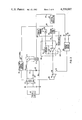
- FIG. 1 schematically shows a prior art transit vehicle propulsion motor control apparatus
- FIG. 2 shows the prior art sawtooth control waveform provided for determining the chopper apparatus operation
- FIG. 3 schematically shows the propulsion motor control apparatus of the present invention
- FIG. 4 shows the randomized sawtooth control waveform of the present invention
- FIG. 5 illustrates the chopper noise harmonic frequencies in relation to one vehicle control signal filter bandpass
- FIG. 6 shows a well known prior art noise signal source
- FIG. 7 shows another well known prior art noise signal source
- FIG. 8 shows a suitable noise source for the propulsion motor control apparatus of FIG. 3.
- FIG. 9 shows a control program flow chart for the noise source of FIG. 8.
- FIG. 1 there is shown a prior art operation control circuit for a transit vehicle propulsion motor control chopper apparatus.
- the chopper 10 regulates the current in the motor circuit 12.
- the main thyristor 14 of the chopper 10 is turned on, by the conduction control apparatus 15 in response to an effort request P signal, this builds up current in the motor circuit 12 by completing the circuit from the positive side of the D.C. power supply 16 through the motor circuit 12 to ground return 18 and then to the negative side of the power supply 16.
- the energy stored in the motor reactor 22 and the inductance of the motor circuit 12 maintains the current flow in the motor circuit 12 through the free wheeling diode 23.
- the average voltage applied to the motor circuit 12 is controlled by adjusting the ratio of the chopper OFF time to the chopper ON time. This adjustment is made by the conduction control apparatus 15 to maintain the desired average motor current and hence the desired motor torque as described in an article published in the Westinghouse Engineer for March 1973 at pages 34 to 41.
- the crystal oscillator 26 provides a control signal at a predetermined rate, such as 218 hertz, to the conduction apparatus 15 to fire ON the main thyristor 14 as required in accordance with the effort request P signal supplied on input 28.
- the crystal oscillator 26 also provides a control signal at the same predetermined rate to the sawtooth generator 30.
- the actual current IM in the motor circuit 12 is sensed by a current transducer 32, such as a Hall effect device, and a current signal 34 is supplied to a first input 36 of the phase control error circuit 38.
- a second input 40 of the error circuit 38 receives a current request signal IR in accordance with the P signal, the sensed vehicle speed and the sensed vehicle weight.
- the error circuit 38 There is a proportional plus integral operation by the error circuit 38 to establish the difference error 42 between the actual motor current IM at input 36 and the requested motor current IR at input 40.
- the comparator 44 operates to compare the error signal 42 with the sawtooth ramp signal 46, and where the error signal 42 intersects the ramp signal 46 establishes when the OFF pulse 48 is provided to fire ON the commutator thyristor 19 and to turn OFF the main thyristor 14.
- the crystal oscillator 26 determines the turn ON time of the main thyristor 14 in response to the effort request P signal 28 operative with the conduction apparatus 15 at the crystal time base such as 218 hertz.
- the turn OFF time of the main thyristor 14 is determined by the error signal 42 in conjunction with the ramp signal 46 as shown in FIG. 2.
- the ramp signal 46 shown in FIG. 2 is provided at the crystal oscillator time base rate, for example 218 hertz.
- the error signal 42 has a magnitude proportional to the historical difference between the actual motor current IM and the requested motor current IR.
- the ramp signal 46 has a predetermined magnitude, such as 10 volts, and the error circuit 42 has a magnitude percentage relationship determined by this current difference, such as 7 volts for a 70% difference and 5 volts for a 50% difference and so forth.
- the crystal oscillator 26 turns ON the main thyristor 14 at time T1.
- the error signal 42 is shown in the example of FIG.
- the comparator 44 fires the commutating thyristor 19 to turn OFF the main thyristor 14. Since the ramp signal 46 occurs at the frequency of the crystal oscillator 46, this provides control signal 48 to establish a desired duty cycle, such as 50%, for the main thyristor 14 with each turn ON and turn OFF cycle occurring at the crystal oscillator frequency.
- the sawtooth generator 30 in response to the output of the crystal oscillator 26 determines the ramp frequency by opening and closing the semiconductor switch 31 and with the capacitor 33 determining the integral shape of the output ramp signal 46.
- the error signal 42 magnitude is supplied to comparator 44 for comparison with the magnitude of the ramp signal 46.
- FIG. 3 there is shown the propulsion motor control apparatus of the present invention, with a variable frequency control of the main thyristor 14.
- the output of the crystal oscillator 26 is supplied to a well known phase lock loop circuit 50, such as described in National Semiconductor Application Note 46 dated June 1971 and entitled "The Phase Locked Loop IC as a Communication System Building Block".
- the sawtooth generator 30 is reset to zero by the output 25 of the monostable 52.
- the phase lock loop circuit 50 compares the output 27 from the oscillator 26 and the feedback ramp signal 25 from the monostable 52 to provide an error signal 29 to the sawtooth generator 30 to assure that the average frequency of the sawtooth ramp output 46 stays the same as the output frequency of the crystal oscillator 26.
- the phase lock loop 50 operates as a frequency comparer that is given a count by the ramp output 46 reaching 10 volts, with the output 25 from the monostable 52 assuring the count of the phase lock loop at this time.
- the error signal 29 from the phase lock loop 50 is supplied to the sawtooth generator 30.
- the noise source 54 which can include a software program operative with memory locations in a digital computer, as shown in FIG.
- An error signal 42 has a voltage magnitude that determines the duty cycle of the thyristor 14 regardless of whether the present cycle output frequency signal 56 has a longer or a shorter time period than the output 27 of the crystal oscillator 26.
- the duty cycle of the main thyristor is determined to be that same percentage regardless of the present cycle frequency deviation of the output 56 from the noise source 54. In this way the requested motor current IR relationship with the actual motor current IM is held as desired, since the voltage magnitude of the error signal 42 in relation to the voltage magnitude of the ramp signal 46 is held substantially constant and determines the duty cycle.
- FIG. 4 there is shown the control ramp signal 46 determined in accordance with the present invention with each ramp signal having the same height, for example 10 volts.
- the error signal 42 is shown for the example of 5 volts to provide a 50% duty cycle for the main thyristor 14.
- the first pulse A has a time period the same as the ramp signal pulses shown in FIG. 2, the second pulse B has a longer time period, the third pulse C has a shorter time period and the fourth pulse D has about the same time period as a ramp signal pulses shown in FIG. 2. Since the magnitude of the error signal 42 has the same fractional relationship with the ramp signal 46, the control duty cycle of the main thyristor 14 will have the same fractional relationship as provided in relation to FIG. 2.
- the control signal 48 is provided to the commutating thyristor 19 to result in a 50% duty cycle control of the main thyristor 14 for each of the ramp signal pulses A, B, C and D. If the magnitude of the error signal 42 changes to 3 volts, this will result in a 30% duty cycle of the main thyristor 14 for each of these ramp signal pulses.
- the motor reactor 22 functions to average out the operational cycles of the main thyristor 14 to maintain the proper motor circuit operation for the actual magnitude relationship of the error signal 42 with the ramp signal 46.
- the noise source 54 shown in FIG. 3 provides a digital frequency output 56 that is changed by the digital-to-analog converter 58 into an analog signal having a magnitude proportional to the frequency difference above or below the predetermined frequency of the output signal 27 from the crystal oscillator. This gives a percentage deviation above or below that predetermined frequency and for each cycle of the output signal 27 the noise source 54 determines what the deviation will be and for the long term the crystal oscillator frequency is followed and this deviation averages out to be zero.
- FIG. 5 there is shown the typical harmonic noise signals provided by the propulsion motor chopper control apparatus shown in FIG. 1.
- the chopper also supplies noise pulses F2, F3, and so forth at integer multiples of that base frequency F1.
- the noise pulse F10 occurs within the bandwidth 60 used for vehicle speed control signalling such as described in above U.S. Pat. No. 3,810,161.
- FIG. 6 there is shown a well known prior art random noise source, including a zener diode 70 operative with the voltage source 80 which is determined to be above the zener breakdown voltage of the zener diode 70 and followed by an amplifier 74 which amplifies the well known voltage variations adjacent to the breakdown knee of the zener diode device 70.
- a well-known sample and hold 76 can be operative to provide an output signal in response to each frequency cycle of the monostable 52.
- FIG. 7 there is shown another well known random noise source generator, including an NPN junction type transistor which is reverse connected in relation to a voltage source 73 and followed by an amplifier 74 and a sample and hold 76 that is responsive to each frequency cycle of operation of the monostable 52.
- the main thyristor 14 of the chopper apparatus shown in FIG. 3 runs at a predetermined base frequency F1, such as 218 hertz, and supplies noise at the base frequency F1 and at each harmonic of F1 up through the higher harmonic.
- F1 base frequency
- the harmonic signals are amplitude modulated in accordance with the phase angle of the chopper 10, how fast the car is going through a given signal block and the location of the car within that signal block in relation to the vehicle control signal receiving antenna. It is difficult to practically miss each and every particular control signal frequency filter bandpass since more than one frequency control signal is used for signalling and it is not practical to select one optimum chopper base frequency to miss all of the utilized signal filter bandpass frequency regions of a typical transit system.
- FIG. 8 there is shown one suitable noise source 54, where a plurality of memory locations of a digital computer, such as a well-known Intel 8080 microprocessor, are utilized to function as shift registers 80, 82 and 84.
- a control program shown in the attached Appendix is executed to shift the stored data in the memory registers 0, 1 and 2.
- the fifth data bit stored in register 0 and the twenty third data bit stored in register 2 are shown fed back to the input of the first register 0 through the exclusive OR 86.
- the random number bits stored in the last register 2 are supplied to a digital to analog converter 88 to provide an output analog voltage signal 56 that is equal to the random number stored in the last register 2.
- This voltage signal 56 operates the switch 31 of the sawtooth generator 30 to deviate the ramp signal 46 in relation to the operational frequency of the main thyristor 14.
- any length random number generator can be provided in accordance with the illustration of FIG. 8.
- FIG. 9 there is shown a flow chart of the control program operative with the noise source 54 shown in FIG. 8.
- the present invention provides for the scrambling or randomizing of the fundamental base frequency of the chopper 10 in accordance with a provided random noise signal 56 to reduce the power of the resulting harmonic chopper noise components.
- This lowers all of the noise component peaks and provides some noise at substantially all frequencies since the chopper frequency keeps changing across a predetermined deviation band of random frequencies and the resulting harmonic noise is discontinuously spread in relation to the same band as the fundamental frequency.
- the harmonic noise becomes more or less overlapping and continuous to reduce the average values of the noise harmonic peaks.
- the harmonic noise signal power in the band of a given bandpass control signal filter is randomly distributed and depending upon the filter characteristics, the filter will not see a coherent signal and will even do some filtering on the chopper harmonic noise itself. Actual tests have been made to establish that the resulting drop in the harmonic noise signal is at least 6 db and could be considerably more than that as determined by a given real time transit system operation.
- the illustrated bandpass 60 of the signal filter as shown in FIG. 5 is indicated as a width and is not intended to indicate signal amplitude relationships.
- the amplitude of the chopper caused harmonic noise will depend upon how far the vehicle carried chopper apparatus is from the signal receiving antenna for a given track signal block. This is a dynamic situation determined by the movement of the vehicle in that signal block. As a vehicle enters a given signal block, the received noise power increases as a vehicle moves in a direction toward and becomes closer to the signal receiver antenna at the opposite end of the signal block.
- the vehicle occupancy detection signal level is injected into a given track signal block at about 100 milliamps, and it is desired that the chopper noise harmonic signals stay at least 20 db below that occupancy signal level.
- each signal filter bandpass is predetermined and it is desired that the chopper noise level within a particular filter bandpass frequency be held at least 20 db below the occupancy signal amplitude within that same bandpass frequency.
- a signal reduction of 20 db is about 1/100 of the signal strength, so this would be a chopper harmonic noise signal of less than 1 milliamp within a given signal bandpass frequency.
- the injected 100 milliamp occupany signal is received at the sensing antenna at substantially that same amplitude, but when a vehicle enters the signal block, the vehicle wheels short across the two-track rails and keep the occupancy signal provided by the signal transmitting antenna from having a predetermined minimum threshold value when sensed by the receiving antenna for establishing vehicle occupancy of that signal block.
- the noise signal injected into that signal block from the vehicle chopper should be kept below the 1 milliamp level so that the chopper noise is not received by the receiving antenna to incorrectly indicate that a vehicle does not occupy that signal block since the control signal receiver might otherwise sense a signal within that signal block above the predetermined threshold value.
- a well-known threshold circuit is operative with the receiving antenna and control signal receiver and the provided predetermined minimum threshold is typically in the order of 60 milliamps. If the chopper noise injected into the signal block is above that 60 milliamp level and within the frequency of the control signal bandpass filter, the threshold circuit would provide an output signal to falsely indicate that the signal block was not occupied by a vehicle. This would be an unsafe condition of operation in regard to required transit system safety. With the vehicle in the signal block and without the chopper noise signal there is not a 60 milliamp control signal sensed by the receiving antenna and control signal receiver.
- the chopper harmonic noise injected into the signal block occupied by the vehicle is reduced in amplitude such that there will not be an adequate threshold signal amplitude within the control signal filter bandpass for the threshold circuit in response to this noise to provide an output signal to indicate falsely that there is no vehicle occupancy of the given signal block.
- this lowers the chopper noise amplitude in relation to the known frequency bandpass of each signal receiver filter that is trying to sense the control signal frequency to determine signal block occupancy by a vehicle.
- the ramp generator 30 permits keeping the on/off ratio or duty cycle of the chopper 10 at the proper level and not changed by the operation of the random noise apparatus 54 and 58.
- the random noise circuit 54 can be implemented by a programmed digital computer as shown in FIG. 8 to include a shift register of length N that is coupled to feedback data to the input of the shift register for generating a pseudo random sequence, with computer memory locations comprising the register and to give different lengths of the ramp signal 46 as a function of the random noise output level.
- the height of the ramp signal 46 provided by the sawtooth generator 30 remains the same and reaches the same voltage of 10 volts.
- phase angle controller error circuit 38 is set for 5 volts to provide a 50% duty cycle, this gives a varying chopper operational period as determined by the length of the ramp signal 46 and equal ON and OFF periods to give a 50% duty cycle.
- the height of the ramp signal 46 is always the same and a given voltage level in the error signal 42 will give the desired ON/OFF duty cycle periods.
- the phase lock loop 50 takes the crystal oscillator frequency and compares this with the feedback ramp signal frequency to generate an output to maintain the desired long time average relationship of these two frequencies the same.
- the signal 46 was reset to zero for every ON pulse from crystal oscillator 26 and then ramped up to 10 volts when another ON pulse would occur. If a 5 volt input error signal 42 was input to the comparator 44, a 50% duty cycle for the main thyristor 14 would result, since the chopper OFF control pulse was determined by where the ramp signal crosses the 5 volt input error signal 42.
- the provided noise source output 56 controls the distance between the ON control pulse 27 and the OFF control pulse 48 for the main thyristor 14.
- the frequency of the chopper 10 does not determine the average motor armature voltage but rather it is the ON/OFF duty time ratio of the chopper 10. As the ramp signal frequency is scrambled, when a 50% duty cycle is required by the transit vehicle operating conditions and requested by the P signal 28, the same 50% duty cycle will still be provided after the random scrambling of the chopper noise frequency.
- the motor armature average voltage is determined by the effective duty cycle of the chopper main thyristor 14.
Abstract
Description
                                  APPENDIX
__________________________________________________________________________
A ASSEMBLY EXAMPLE
__________________________________________________________________________
RAND:
     PUSH
         B      ;
                 Save B&C Registers
     LOA MEMORY 0
                ;
                 First Do Exclusive Or
     RAR
     RAR
     RAR        ;
                 "S" In Bit 0
     MOV B A    ;
                 Store in Temporary B
     LOA MEMORY 2
     RAR        ;
                 "23" in Bit 0
     XRA B      ;
                 Exclusive Or Bit "0" With Temporary
     RAR        ;
                 Move Result Into Carry Bit
     LOA MEMORY 0
     RAR        ;
                 Carry To A7 "1"), A0 ("8") To Carry
     STA MEMORY 0
                ;
                 Store New Memory 0
     LOA MEMORY 1
     RAR        ;
                 Carry ("8") to A7 ("9"), A0 ("16") To Carry
     STA MEMORY 1
                ;
                 Store New Memory 1
     LOA MEMORY 2
     RAR        ;
                 Carry ("16") To A7 ("17"); Carry Will Be Thrown Away
     STA MEMORY 2
                ;
                 Store New Memory 2
     OUT "DIA"  ;
                 Output To D/A Converter
     POP B      ;
                 Restore B&C Registers
     RET        ;
                 Return to Main Program
__________________________________________________________________________
Claims (10)
Priority Applications (9)
| Application Number | Priority Date | Filing Date | Title |
|---|---|---|---|
| US06/149,358 US4339697A (en) | 1980-05-13 | 1980-05-13 | Propulsion motor control apparatus and method |
| CA000376515A CA1152611A (en) | 1980-05-13 | 1981-04-29 | Propulsion motor control apparatus and method |
| BR8102896A BR8102896A (en) | 1980-05-13 | 1981-05-11 | CONTROL DEVICE FOR ELECTRIC MOTOR AND CONTROL PROCESS OF SUPPLY CURRENT TO A VEHICLE DRIVE ENGINE |
| JP6947781A JPS576501A (en) | 1980-05-13 | 1981-05-11 | Current controlling method and device |
| IT41573/81A IT1146870B (en) | 1980-05-13 | 1981-05-12 | APPARATUS AND PROCEDURE FOR THE CONTROL OF PROPULSION ENGINES |
| ES502115A ES502115A0 (en) | 1980-05-13 | 1981-05-12 | A CONTROL DEVICE FOR A MOTOR, TOGETHER WITH A CORRESPONDING CONTROL METHOD. |
| FR8109551A FR2482798A1 (en) | 1980-05-13 | 1981-05-13 | APPARATUS AND METHOD FOR CONTROLLING A PROPULSION ENGINE |
| KR1019810001649A KR850000314B1 (en) | 1980-05-13 | 1981-05-13 | Propulsion motor control apparatus |
| BE0/204776A BE888791A (en) | 1980-05-13 | 1981-05-13 | APPARATUS AND METHOD FOR CONTROLLING A PROPULSION MOTOR |
Applications Claiming Priority (1)
| Application Number | Priority Date | Filing Date | Title |
|---|---|---|---|
| US06/149,358 US4339697A (en) | 1980-05-13 | 1980-05-13 | Propulsion motor control apparatus and method |
Publications (1)
| Publication Number | Publication Date |
|---|---|
| US4339697A true US4339697A (en) | 1982-07-13 |
Family
ID=22529934
Family Applications (1)
| Application Number | Title | Priority Date | Filing Date |
|---|---|---|---|
| US06/149,358 Expired - Lifetime US4339697A (en) | 1980-05-13 | 1980-05-13 | Propulsion motor control apparatus and method |
Country Status (9)
| Country | Link |
|---|---|
| US (1) | US4339697A (en) |
| JP (1) | JPS576501A (en) |
| KR (1) | KR850000314B1 (en) |
| BE (1) | BE888791A (en) |
| BR (1) | BR8102896A (en) |
| CA (1) | CA1152611A (en) |
| ES (1) | ES502115A0 (en) |
| FR (1) | FR2482798A1 (en) |
| IT (1) | IT1146870B (en) |
Cited By (20)
| Publication number | Priority date | Publication date | Assignee | Title |
|---|---|---|---|---|
| US4390825A (en) * | 1981-06-26 | 1983-06-28 | E. I. Du Pont De Nemours & Co. | Auto-threshold slow start control circuit for a centrifuge |
| US4394724A (en) * | 1981-10-30 | 1983-07-19 | Westinghouse Electric Corp. | Propulsion motor control apparatus and method |
| US4651070A (en) * | 1985-08-01 | 1987-03-17 | Westinghouse Electric Corp. | Transit vehicle start-up propulsion motor control apparatus and method |
| US4684859A (en) * | 1984-11-16 | 1987-08-04 | Hitachi, Ltd. | Chopper control system |
| US4685000A (en) * | 1985-09-16 | 1987-08-04 | Eastman Kodak Company | Inhibition of exposure in a video printer upon loss of color filter sync |
| US4950091A (en) * | 1988-01-11 | 1990-08-21 | Harada Kogyo Kabushiki Kaisha | Rod antenna control system for automobiles |
| US5036268A (en) * | 1986-11-26 | 1991-07-30 | Dynawatt Oy | Procedure and apparatus for producing an a.c. voltage |
| US5045712A (en) * | 1985-03-28 | 1991-09-03 | Raytheon Company | Synchronized switched mode power supplies |
| US6043996A (en) * | 1999-02-03 | 2000-03-28 | General Electric Company | Method and apparatus for reducing monotonic audible noise in a power conversion system |
| EP1134878A1 (en) * | 2000-03-13 | 2001-09-19 | Alstom Belgium S.A. | Method and device for reduction of harmonics in power converters |
| EP1216526A1 (en) * | 1999-09-17 | 2002-06-26 | Delphi Technologies, Inc. | Reduction of emi through switching frequency dithering |
| US6571263B1 (en) * | 1998-08-19 | 2003-05-27 | System Industrial Laboratory Do., Ltd | Random number generating apparatus |
| WO2003079526A2 (en) * | 2002-03-14 | 2003-09-25 | Tyco Electronics Corporation | Cmos digital pulse width modulation controller |
| US6763364B1 (en) * | 1995-02-14 | 2004-07-13 | Scott A. Wilber | Random number generator and generation method |
| US6775164B2 (en) | 2002-03-14 | 2004-08-10 | Tyco Electronics Corporation | Three-terminal, low voltage pulse width modulation controller IC |
| US20050163237A1 (en) * | 2004-01-27 | 2005-07-28 | Nippon Yusoki Co., Ltd. | Multi-phase carrier signal generator and multi-phase carrier signal generation method |
| US20050174076A1 (en) * | 2004-02-09 | 2005-08-11 | Nippon Yusoki Co., Ltd. | Inverter control apparatus and inverter control method |
| US20150048771A1 (en) * | 2012-03-21 | 2015-02-19 | Valeo Systèmes d'Essuyage | Method and device for controlling a motor vehicle windscreen wiper motor |
| EP3576285A1 (en) * | 2018-05-29 | 2019-12-04 | Siemens Aktiengesellschaft | Energy converter |
| DE102005062451B4 (en) * | 2004-12-28 | 2021-02-04 | Denso Corporation | Electrical power switching device that provides a reduced level of noise interference with radio links |
Families Citing this family (1)
| Publication number | Priority date | Publication date | Assignee | Title |
|---|---|---|---|---|
| JPH02228713A (en) * | 1989-03-01 | 1990-09-11 | Rinnai Corp | Energizing quantity controller for electric appliance |
Citations (3)
| Publication number | Priority date | Publication date | Assignee | Title |
|---|---|---|---|---|
| US4042873A (en) * | 1976-11-26 | 1977-08-16 | Guldon Industries, Inc. | Phase locked firing circuit for SCRS, or the like |
| US4099109A (en) * | 1976-10-01 | 1978-07-04 | Westinghouse Electric Corp. | Digital apparatus for synthesizing pulse width modulated waveforms and digital pulse width modulated control system |
| US4190882A (en) * | 1977-05-05 | 1980-02-26 | Hughes Aircraft Company | System for reducing the effects of power supply switching |
-
1980
- 1980-05-13 US US06/149,358 patent/US4339697A/en not_active Expired - Lifetime
-
1981
- 1981-04-29 CA CA000376515A patent/CA1152611A/en not_active Expired
- 1981-05-11 JP JP6947781A patent/JPS576501A/en active Pending
- 1981-05-11 BR BR8102896A patent/BR8102896A/en unknown
- 1981-05-12 IT IT41573/81A patent/IT1146870B/en active
- 1981-05-12 ES ES502115A patent/ES502115A0/en active Granted
- 1981-05-13 BE BE0/204776A patent/BE888791A/en not_active IP Right Cessation
- 1981-05-13 KR KR1019810001649A patent/KR850000314B1/en active IP Right Grant
- 1981-05-13 FR FR8109551A patent/FR2482798A1/en active Pending
Patent Citations (3)
| Publication number | Priority date | Publication date | Assignee | Title |
|---|---|---|---|---|
| US4099109A (en) * | 1976-10-01 | 1978-07-04 | Westinghouse Electric Corp. | Digital apparatus for synthesizing pulse width modulated waveforms and digital pulse width modulated control system |
| US4042873A (en) * | 1976-11-26 | 1977-08-16 | Guldon Industries, Inc. | Phase locked firing circuit for SCRS, or the like |
| US4190882A (en) * | 1977-05-05 | 1980-02-26 | Hughes Aircraft Company | System for reducing the effects of power supply switching |
Cited By (26)
| Publication number | Priority date | Publication date | Assignee | Title |
|---|---|---|---|---|
| US4390825A (en) * | 1981-06-26 | 1983-06-28 | E. I. Du Pont De Nemours & Co. | Auto-threshold slow start control circuit for a centrifuge |
| US4394724A (en) * | 1981-10-30 | 1983-07-19 | Westinghouse Electric Corp. | Propulsion motor control apparatus and method |
| US4684859A (en) * | 1984-11-16 | 1987-08-04 | Hitachi, Ltd. | Chopper control system |
| US5045712A (en) * | 1985-03-28 | 1991-09-03 | Raytheon Company | Synchronized switched mode power supplies |
| US4651070A (en) * | 1985-08-01 | 1987-03-17 | Westinghouse Electric Corp. | Transit vehicle start-up propulsion motor control apparatus and method |
| US4685000A (en) * | 1985-09-16 | 1987-08-04 | Eastman Kodak Company | Inhibition of exposure in a video printer upon loss of color filter sync |
| US5036268A (en) * | 1986-11-26 | 1991-07-30 | Dynawatt Oy | Procedure and apparatus for producing an a.c. voltage |
| US4950091A (en) * | 1988-01-11 | 1990-08-21 | Harada Kogyo Kabushiki Kaisha | Rod antenna control system for automobiles |
| US6763364B1 (en) * | 1995-02-14 | 2004-07-13 | Scott A. Wilber | Random number generator and generation method |
| US6571263B1 (en) * | 1998-08-19 | 2003-05-27 | System Industrial Laboratory Do., Ltd | Random number generating apparatus |
| US6043996A (en) * | 1999-02-03 | 2000-03-28 | General Electric Company | Method and apparatus for reducing monotonic audible noise in a power conversion system |
| EP1216526A4 (en) * | 1999-09-17 | 2006-06-07 | Delphi Tech Inc | Reduction of emi through switching frequency dithering |
| EP1216526A1 (en) * | 1999-09-17 | 2002-06-26 | Delphi Technologies, Inc. | Reduction of emi through switching frequency dithering |
| EP1134878A1 (en) * | 2000-03-13 | 2001-09-19 | Alstom Belgium S.A. | Method and device for reduction of harmonics in power converters |
| WO2001069765A1 (en) * | 2000-03-13 | 2001-09-20 | Alstom Belgium S.A. | Method and device for reducing harmonics in power converters |
| WO2003079526A2 (en) * | 2002-03-14 | 2003-09-25 | Tyco Electronics Corporation | Cmos digital pulse width modulation controller |
| WO2003079526A3 (en) * | 2002-03-14 | 2003-12-24 | Tyco Electronics Corp | Cmos digital pulse width modulation controller |
| US6775164B2 (en) | 2002-03-14 | 2004-08-10 | Tyco Electronics Corporation | Three-terminal, low voltage pulse width modulation controller IC |
| US20050163237A1 (en) * | 2004-01-27 | 2005-07-28 | Nippon Yusoki Co., Ltd. | Multi-phase carrier signal generator and multi-phase carrier signal generation method |
| US20050174076A1 (en) * | 2004-02-09 | 2005-08-11 | Nippon Yusoki Co., Ltd. | Inverter control apparatus and inverter control method |
| DE102005062451B4 (en) * | 2004-12-28 | 2021-02-04 | Denso Corporation | Electrical power switching device that provides a reduced level of noise interference with radio links |
| DE102005062451B9 (en) * | 2004-12-28 | 2021-04-08 | Denso Corporation | Electrical power switching device that provides a reduced level of noise interference with radio links |
| US20150048771A1 (en) * | 2012-03-21 | 2015-02-19 | Valeo Systèmes d'Essuyage | Method and device for controlling a motor vehicle windscreen wiper motor |
| US9438154B2 (en) * | 2012-03-21 | 2016-09-06 | Valeo Systèmes d'Essuyage | Method and device for controlling a motor vehicle windscreen wiper motor |
| EP3576285A1 (en) * | 2018-05-29 | 2019-12-04 | Siemens Aktiengesellschaft | Energy converter |
| WO2019228758A1 (en) * | 2018-05-29 | 2019-12-05 | Siemens Aktiengesellschaft | Energy converter |
Also Published As
| Publication number | Publication date |
|---|---|
| FR2482798A1 (en) | 1981-11-20 |
| CA1152611A (en) | 1983-08-23 |
| ES8300211A1 (en) | 1982-10-01 |
| BR8102896A (en) | 1982-02-02 |
| IT8141573A0 (en) | 1981-05-12 |
| JPS576501A (en) | 1982-01-13 |
| ES502115A0 (en) | 1982-10-01 |
| IT1146870B (en) | 1986-11-19 |
| KR830006979A (en) | 1983-10-12 |
| KR850000314B1 (en) | 1985-03-18 |
| BE888791A (en) | 1981-11-13 |
Similar Documents
| Publication | Publication Date | Title |
|---|---|---|
| US4339697A (en) | Propulsion motor control apparatus and method | |
| US4218655A (en) | Method and apparatus for transmitting intelligence over a carrier wave | |
| US4106007A (en) | Method and apparatus for transmitting intelligence over a carrier wave | |
| US3657625A (en) | System for blending dynamic and regenerative braking | |
| US4352049A (en) | Brake control apparatus and method | |
| CA1085034A (en) | Alternating current track circuits | |
| JPS586364B2 (en) | Braking control system for chopper electric cars | |
| US5345358A (en) | Method for evaluating operability of filter components in power conversion system | |
| US3593089A (en) | System for blending dynamic and regenerative braking | |
| RU2400388C1 (en) | Stationary transceiver, multi-purpose generator and multi-purpose receiver of train speed acs | |
| US3402289A (en) | Automatic control system for vehicles incorporating a ranging system for vehicle traffic safety control | |
| EP0059924B1 (en) | Control apparatus for electric cars propelled by induction motor | |
| US4651070A (en) | Transit vehicle start-up propulsion motor control apparatus and method | |
| US4340880A (en) | Method and apparatus for signal recognition in a remote control system with influencing of the zero point transition of the alternating-current mains voltage | |
| US4188002A (en) | Vital power varistor circuit for railroad signaling systems | |
| JPH10215184A (en) | Decoding method, bus system, peripheral unit and device for transmitting information | |
| US3958781A (en) | Train vehicle protection apparatus including signal block occupancy determination | |
| US4002314A (en) | Train vehicle speed control signal providing apparatus | |
| US5041745A (en) | Failsafe bandpass filter/decoder | |
| US3566103A (en) | Rail vehicle control systems | |
| JP3340769B2 (en) | Train detection device | |
| US3562515A (en) | Tapered braking rate for traction vehicles | |
| JPS5917635B2 (en) | PWM inverter device | |
| Watanabe et al. | Advanced automatic train protection system | |
| JP2989601B1 (en) | Point control type signal sorting device |
Legal Events
| Date | Code | Title | Description |
|---|---|---|---|
| STCF | Information on status: patent grant |
Free format text: PATENTED CASE |
|
| AS | Assignment |
Owner name: AEG WESTINGHOUSE TRANSPORTATION SYSTEMS, INC., 200 Free format text: ASSIGNMENT OF ASSIGNORS INTEREST.;ASSIGNOR:WESTINGHOUSE ELECTRIC CORPORATION;REEL/FRAME:004963/0339 Effective date: 19880930 Owner name: AEG WESTINGHOUSE TRANSPORTATION SYSTEMS, INC., A C Free format text: ASSIGNMENT OF ASSIGNORS INTEREST;ASSIGNOR:WESTINGHOUSE ELECTRIC CORPORATION;REEL/FRAME:004963/0339 Effective date: 19880930 |
|
| AS | Assignment |
Owner name: ABB DAIMLER-BENZ TRANSPORTATION (NORTH AMERICA) IN Free format text: CHANGE OF NAME;ASSIGNOR:AEG TRANSPORTATION SYSTEMS, INC.;REEL/FRAME:007894/0001 Effective date: 19960102 |
|
| AS | Assignment |
Owner name: ABB DAIMLER-BENZ TRANSPORATION (NORTH AMERICA) INC Free format text: CHANGE OF NAME;ASSIGNOR:AEG TRANSPORTATION SYSTEMS, INC.;REEL/FRAME:008162/0582 Effective date: 19960102 |