US4348647A - Stability enhanced rare-gas monofluoride lasers - Google Patents
Stability enhanced rare-gas monofluoride lasers Download PDFInfo
- Publication number
- US4348647A US4348647A US06/156,547 US15654780A US4348647A US 4348647 A US4348647 A US 4348647A US 15654780 A US15654780 A US 15654780A US 4348647 A US4348647 A US 4348647A
- Authority
- US
- United States
- Prior art keywords
- gas
- sub
- fluorine
- laser
- rare
- Prior art date
- Legal status (The legal status is an assumption and is not a legal conclusion. Google has not performed a legal analysis and makes no representation as to the accuracy of the status listed.)
- Expired - Lifetime
Links
- 239000007789 gas Substances 0.000 claims abstract description 47
- 229910052731 fluorine Inorganic materials 0.000 claims abstract description 40
- 239000011737 fluorine Substances 0.000 claims abstract description 39
- YCKRFDGAMUMZLT-UHFFFAOYSA-N Fluorine atom Chemical compound [F] YCKRFDGAMUMZLT-UHFFFAOYSA-N 0.000 claims abstract description 37
- 238000010894 electron beam technology Methods 0.000 claims abstract description 21
- QKCGXXHCELUCKW-UHFFFAOYSA-N n-[4-[4-(dinaphthalen-2-ylamino)phenyl]phenyl]-n-naphthalen-2-ylnaphthalen-2-amine Chemical compound C1=CC=CC2=CC(N(C=3C=CC(=CC=3)C=3C=CC(=CC=3)N(C=3C=C4C=CC=CC4=CC=3)C=3C=C4C=CC=CC4=CC=3)C3=CC4=CC=CC=C4C=C3)=CC=C21 QKCGXXHCELUCKW-UHFFFAOYSA-N 0.000 claims abstract description 17
- 239000000203 mixture Substances 0.000 claims abstract description 15
- 230000002459 sustained effect Effects 0.000 claims abstract description 10
- 230000005684 electric field Effects 0.000 claims description 20
- 230000006872 improvement Effects 0.000 claims description 5
- 239000002737 fuel gas Substances 0.000 claims 3
- 238000000034 method Methods 0.000 abstract description 46
- 230000008569 process Effects 0.000 abstract description 43
- 239000000446 fuel Substances 0.000 abstract description 18
- 229910052736 halogen Inorganic materials 0.000 abstract description 9
- 150000002367 halogens Chemical class 0.000 abstract description 9
- GVGCUCJTUSOZKP-UHFFFAOYSA-N nitrogen trifluoride Chemical compound FN(F)F GVGCUCJTUSOZKP-UHFFFAOYSA-N 0.000 abstract description 7
- 238000010791 quenching Methods 0.000 abstract description 6
- 230000000171 quenching effect Effects 0.000 abstract description 6
- 230000000694 effects Effects 0.000 abstract description 4
- 230000003111 delayed effect Effects 0.000 abstract description 3
- 150000002366 halogen compounds Chemical class 0.000 abstract 1
- XKRFYHLGVUSROY-UHFFFAOYSA-N Argon Chemical compound [Ar] XKRFYHLGVUSROY-UHFFFAOYSA-N 0.000 description 20
- 230000001419 dependent effect Effects 0.000 description 13
- 230000005283 ground state Effects 0.000 description 11
- DNNSSWSSYDEUBZ-UHFFFAOYSA-N krypton atom Chemical compound [Kr] DNNSSWSSYDEUBZ-UHFFFAOYSA-N 0.000 description 11
- 238000004519 manufacturing process Methods 0.000 description 11
- 241000894007 species Species 0.000 description 11
- 229910052786 argon Inorganic materials 0.000 description 9
- 229910052743 krypton Inorganic materials 0.000 description 9
- VZPPHXVFMVZRTE-UHFFFAOYSA-N [Kr]F Chemical compound [Kr]F VZPPHXVFMVZRTE-UHFFFAOYSA-N 0.000 description 7
- 125000001153 fluoro group Chemical group F* 0.000 description 7
- 239000011888 foil Substances 0.000 description 7
- 230000003321 amplification Effects 0.000 description 6
- 150000004820 halides Chemical class 0.000 description 6
- 238000003199 nucleic acid amplification method Methods 0.000 description 6
- ISQINHMJILFLAQ-UHFFFAOYSA-N argon hydrofluoride Chemical compound F.[Ar] ISQINHMJILFLAQ-UHFFFAOYSA-N 0.000 description 3
- 125000004429 atom Chemical group 0.000 description 3
- -1 fluorine ions Chemical class 0.000 description 3
- 239000012212 insulator Substances 0.000 description 3
- 239000002245 particle Substances 0.000 description 3
- 230000002123 temporal effect Effects 0.000 description 3
- 230000015572 biosynthetic process Effects 0.000 description 2
- 238000006243 chemical reaction Methods 0.000 description 2
- 230000005284 excitation Effects 0.000 description 2
- 230000001965 increasing effect Effects 0.000 description 2
- 150000002500 ions Chemical class 0.000 description 2
- 230000007935 neutral effect Effects 0.000 description 2
- 230000003068 static effect Effects 0.000 description 2
- KRHYYFGTRYWZRS-UHFFFAOYSA-M Fluoride anion Chemical compound [F-] KRHYYFGTRYWZRS-UHFFFAOYSA-M 0.000 description 1
- 101150108015 STR6 gene Proteins 0.000 description 1
- 101100386054 Saccharomyces cerevisiae (strain ATCC 204508 / S288c) CYS3 gene Proteins 0.000 description 1
- RTAQQCXQSZGOHL-UHFFFAOYSA-N Titanium Chemical compound [Ti] RTAQQCXQSZGOHL-UHFFFAOYSA-N 0.000 description 1
- 238000010521 absorption reaction Methods 0.000 description 1
- 230000004913 activation Effects 0.000 description 1
- 238000007792 addition Methods 0.000 description 1
- 239000000654 additive Substances 0.000 description 1
- 230000000996 additive effect Effects 0.000 description 1
- XAGFODPZIPBFFR-UHFFFAOYSA-N aluminium Chemical compound [Al] XAGFODPZIPBFFR-UHFFFAOYSA-N 0.000 description 1
- 229910052782 aluminium Inorganic materials 0.000 description 1
- 238000004458 analytical method Methods 0.000 description 1
- 230000009849 deactivation Effects 0.000 description 1
- 230000003247 decreasing effect Effects 0.000 description 1
- 238000010586 diagram Methods 0.000 description 1
- ULFHSQLFQYTZLS-UHFFFAOYSA-N difluoroamine Chemical compound FNF ULFHSQLFQYTZLS-UHFFFAOYSA-N 0.000 description 1
- 230000002708 enhancing effect Effects 0.000 description 1
- 230000004048 modification Effects 0.000 description 1
- 238000012986 modification Methods 0.000 description 1
- 229910052754 neon Inorganic materials 0.000 description 1
- GKAOGPIIYCISHV-UHFFFAOYSA-N neon atom Chemical compound [Ne] GKAOGPIIYCISHV-UHFFFAOYSA-N 0.000 description 1
- 229910017051 nitrogen difluoride Inorganic materials 0.000 description 1
- 230000003287 optical effect Effects 0.000 description 1
- 230000002028 premature Effects 0.000 description 1
- 238000004451 qualitative analysis Methods 0.000 description 1
- 239000002516 radical scavenger Substances 0.000 description 1
- 230000009467 reduction Effects 0.000 description 1
- 238000001228 spectrum Methods 0.000 description 1
- 230000000087 stabilizing effect Effects 0.000 description 1
- 229910001220 stainless steel Inorganic materials 0.000 description 1
- 239000010935 stainless steel Substances 0.000 description 1
- 101150035983 str1 gene Proteins 0.000 description 1
- 239000000126 substance Substances 0.000 description 1
- 229910052719 titanium Inorganic materials 0.000 description 1
- 239000010936 titanium Substances 0.000 description 1
- 238000003466 welding Methods 0.000 description 1
- 229910052724 xenon Inorganic materials 0.000 description 1
- FHNFHKCVQCLJFQ-UHFFFAOYSA-N xenon atom Chemical compound [Xe] FHNFHKCVQCLJFQ-UHFFFAOYSA-N 0.000 description 1
Images
Classifications
-
- H—ELECTRICITY
- H01—ELECTRIC ELEMENTS
- H01S—DEVICES USING THE PROCESS OF LIGHT AMPLIFICATION BY STIMULATED EMISSION OF RADIATION [LASER] TO AMPLIFY OR GENERATE LIGHT; DEVICES USING STIMULATED EMISSION OF ELECTROMAGNETIC RADIATION IN WAVE RANGES OTHER THAN OPTICAL
- H01S3/00—Lasers, i.e. devices using stimulated emission of electromagnetic radiation in the infrared, visible or ultraviolet wave range
- H01S3/14—Lasers, i.e. devices using stimulated emission of electromagnetic radiation in the infrared, visible or ultraviolet wave range characterised by the material used as the active medium
- H01S3/22—Gases
- H01S3/223—Gases the active gas being polyatomic, i.e. containing two or more atoms
- H01S3/225—Gases the active gas being polyatomic, i.e. containing two or more atoms comprising an excimer or exciplex
-
- H—ELECTRICITY
- H01—ELECTRIC ELEMENTS
- H01S—DEVICES USING THE PROCESS OF LIGHT AMPLIFICATION BY STIMULATED EMISSION OF RADIATION [LASER] TO AMPLIFY OR GENERATE LIGHT; DEVICES USING STIMULATED EMISSION OF ELECTROMAGNETIC RADIATION IN WAVE RANGES OTHER THAN OPTICAL
- H01S3/00—Lasers, i.e. devices using stimulated emission of electromagnetic radiation in the infrared, visible or ultraviolet wave range
- H01S3/09—Processes or apparatus for excitation, e.g. pumping
- H01S3/097—Processes or apparatus for excitation, e.g. pumping by gas discharge of a gas laser
- H01S3/09707—Processes or apparatus for excitation, e.g. pumping by gas discharge of a gas laser using an electron or ion beam
Definitions
- This invention relates to rare-gas monofluoride lasers, and more particularly to enhancing the stability of the electric discharge used to excite such lasers by means of a two-component halogen mixture which favorably alters the halogen kinetics.
- Such lasers depend on electron collisional processes for excitation of the molecule into the upper laser level. Therefore, the lasers can be pumped either by electron guns or by electric discharges. Because the overall processes result in temperature increases on the order of 100° C. per microsecond, and halogen fuel consumption can be on the order of 20%-50% per microsecond, only pulsed operation, of about several microseconds duration, is possible. In order to provide for scalability to large volumes and long pulse lengths (e.g., 1 microsecond) while limiting the burden of the electron beam technology required, the rare-gas monohalide lasers have typically been pumped by means of electron beam sustained electric discharges.
- halide lasers have been shown to have a theoretical capability of useful production of ultraviolet and/or visible laser pulses, scalable into the tens of kilowatt regime, with acceptable efficiencies of on the order of 1% or greater, the practical implementation thereof has been impeded by the inability to maintain stable discharge conditions to acquire a pulse of an adequate duration, with a sufficient laser intensity amplification factor, to render such lasers practical for use.
- Objects of the invention include stabilizing discharges in electron beam sustained, electric discharge rare-gas monofluoride lasers.
- a rare-gas monofluoride laser employs a gas mixture including nitrogen trifluoride which has a rate coefficient for electron dissociative attachment which is approximately four times larger than that of the fluorine fuel, and a rate coefficient of rare-gas metastable atom quenching which is approximately six times smaller than that of the fluorine fuel.
- the nitrogen trifluoride is provided in the laser gas mixture in an amount that is on the order of one-tenth of the amount of fluorine fuel.
- the present invention provides a relatively low cost method of delaying the onset of discharge instability in rare-gas monofluoride lasers.
- the invention may be used alone, or in combination with one or more electronic methods of delaying the onset of discharge instability, such as those disclosed and claimed in our commonly owned, copending application Ser. No. 132,018 filed on Mar. 20, 1980 and entitled STABILITY ENHANCED HALIDE LASERS.
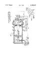
- FIG. 1 is a simplified schematic diagram of an electron beam sustained electric discharge, flowing, pulsed rare-gas monohalide laser incorporating the present invention.
- FIG. 2 is a simplified illustration of a laser configuration.
- exemplary laser apparatus incorporates a laser cavity (not shown) disposed within a chamber 10 in which the chemical and electrical processes relating to the invention take place.
- the laser gain path (such as between conventional confocal, or other mirrors forming an optical oscillator) is perpendicular both to the electric field and the gas flow in the apparatus of FIG. 1.
- the laser gain path is perpendicular to the plane of the drawing.
- the laser cavity (that is, the dimension perpendicular to the sheet as seen in FIG. 1) may be on the order of one meter long, and both the height of the chamber (as seen in FIG. 1) and the distance between the cathode and the anode may be on the order of several centimeters or more.
- Gas control apparatus 12 is connected by suitable conduits 14, 16 to the chamber 10 and provides a suitable gas mixture, such as 0.95 argon, 0.05 krypton, and 0.005 fluorine.
- a suitable gas mixture such as 0.95 argon, 0.05 krypton, and 0.005 fluorine.
- Other gas mixtures may be used, such as different mixture fractions of argon, krypton, fluorine and nitrogen trifluoride, or such as may be appropriate for other rare-gas halide lasers (e.g., XeF*, using neon, xenon, nitrogen trifluoride mixtures).
- the gas system may be open cycle, providing gas flow from tanks and causing the exit gas to pass through a scavenger system (or to atmosphere) or, may be a closed cycle system including a circulation pump; and perhaps a slight bleed with a makeup gas inlet may be employed. Or a static (no flow) sealed system may be used for single pulse (very low PRF) operation. All of this is within the skill of the art and forms no part of the present invention.
- the electric field is provided within the chamber 10 between an anode 18 and a cathode 20.
- the cathode 20 can vary in its configuration, but may comprise a screen of orthogonal mesh, with twenty, 12-mil wires per inch, or the like.
- the cathode 20 may be secured to walls 21, 22 of the chamber 10 with a heavy collar (not shown) or by spot welding, since it needs only a limited amount of mechanical stability and electrical contact with the walls of the chamber 10, which are electrical ground.
- the anode 18 is provided with a suitable connection 24, within a suitable insulator or insulating wall 25, to the positive output of a high voltage pulse circuit 26, the negative output of which is grounded to the wall 21 of the chamber 10. This establishes an electric field gradient from the anode 18 to the cathode 20, in the well known fashion.
- an electron beam gun 30 includes a thin foil cathode 32, disposed in a vacuum and supported by a low field concentration metallic structure 33.
- the cathode is disposed in a vacuum chamber 34, which may be evacuated to 10 -5 Torr, or so.
- the electrons are accelerated toward a thin foil window 36 which separates the vacuum chamber 34 from the atmospheric pressure of the lasing chamber 10.
- the window 36 may comprise a foil of titanium, stainless steel, aluminum, or the like, and may be on the order of 1 mil thick.
- the foil window may be on the order of 10 ⁇ 100 centimeters.
- Support for the foil is provided by a much thicker grate-like structure 38, which may resemble a hibachi grill grating, that is fastened in a suitable way, such as by screws or bolts 40, to the walls 21, 22 of the chamber 10.
- An O-ring 42 may be provided to ensure a gas-tight seal between the foil window 36 and the walls 21, 22.
- the foil is electrically grounded, along with the walls of the chambers 34, 10 and therefore represents the anode of the electron gun.
- the electron gun cathode structure 33 is mounted by means of suitable insulator 44 through the wall of a dielectric oil chamber 46, within which high voltage pulse circuitry 48 is disposed.
- the dielectric oil avoids arcing and corona effects which might otherwise attend the high voltage pulse circuitry 48, since this circuitry may typically operate at several hundred kilovolts.
- Suitable connections such as a negative voltage line 50 from a high voltage source 52 and a trigger pulse line 54 from a pulse repetition frequency clock 56, may be made through a conduit 58 that is isolated from the wall 60 of the chamber 46 by means of a suitable insulator 62.
- the walls 21, 22 and 60 are all at the same ground potential, due to connections 64.
- the positive side of the kilovolt source 52 is also connected to ground.
- the electron beam gun 30 comprises a cold cathode gun operative in a space-charge-limited mode.
- current densities in the range of 0.5-2.0 amps per square centimeter are typical.
- current densities can be varied from 0.7 amps per square centimeter to 1.5 amps per square centimeter, as the cathode voltage is varied from 200 KeV to 400 KeV.
- three, single-turn magnetic coils 68-70 are connected, by respective suitable connections 72-74, to magnetic driving circuitry 76, which provides suitable current to the coils 68-70 to focus, or as described more fully in our aforementioned copending application, to defocus the electron beam.
- the coils may comprise single turns of heavy wire, on the order of two cm diameter, and the current in the various coils may be constant, or programmed in accordance with the invention of the aforementioned copending application, with magnitudes on the order of 5,000 amps to 30,000 amps.
- no magnetic fields may be required at all, and in other instances only a single coil may be required (such as the coil 68) in order to provide desired focusing, in dependence upon the particular configuration in which the invention may be practiced.
- the magnetic driving circuitry 76 as well as the high voltage pulse circuit 26 may be connected to a delayed pulse repetition frequency clock signal line 78 which is connected through a delay circuit 80 to the pulse repetition frequency clock 56.
- the delay circuit 80 may cause the electric field 26 to be established a short time (on the order of 70 nanoseconds) after activation of the electron gun 30, so as to conserve energy until maximum current density output of the electron gun is achieved. On the other hand, such a delay need not be used if not deemed desirable in any implementation of the present invention.
- the high voltage pulse circuit 26 could be arranged, with respect to the pulse repetition frequency clock 56, so as to shut off a short time (such as on the order of 250 nanoseconds) before deactivation of the electron beam, similarly to conserve energy. But, as seen in FIG. 1, this option is not included, since it is not essential in a laser employing the invention.
- the electron beam sustained electric discharge rare-gas monofluoride laser includes a variety of processes in order to provide laser pulses with a sufficient laser intensity amplification factor.
- an electron beam is established, following which an electric field is created.
- an electric field is created.
- on the order of fifty to one hundred nanoseconds may be provided in order for maximum current density of the electron beam gun output to be achieved prior to establishing the electric field, in order to minimize power utilization.
- a suitable gas mixture such as 0.95 argon, 0.05 krypton, and 0.005 fluorine (in fractional number density per unit volume), is present in the laser cavity across which the electric field is established and into which the electron beam is deposed.
- the high energy, primary electrons from the electron beam source collide with all of the molecules in the mixture, creating secondary electrons. Since the kinetics of the electron-fluorine collisions are not productive of significant numbers of electrons, the creation of secondary electrons by means of collision with primary electrons is substantially limited to argon and krypton, as set forth in processes 1 and 2 hereinafter.
- the electric field accelerates the secondary electrons, and is designed to provide, for the kinetics involved, secondary electrons of an energy level which are, on average, highly productive of krypton atoms excited to the first electronic energy state (process 3, hereinafter).
- the excited krypton atoms collide with the fluorine molecules to produce excited krypton monofluoride molecules and fluorine atoms (process 4, hereinafter); the excited krypton monofluoride first electron energy state is an upper laser level, so that the excited molecule radiates (providing useful laser output energy) and reduces to the ground state.
- the ground state krypton monofluoride is repulsive, and the atoms dissociate, being unable to survive in the ground state.
- suitably energized secondary electrons also collide with ground state argon atoms to provide argon atoms excited to the first electronic energy state thereof (process 5, hereinafter) which in turn collide with fluorine molecules to provide argon monofluoride in a first electronic state and fluorine atoms (process 6, hereinafter).
- the excited argon monofluoride molecules collide with ground state krypton atoms to form excited krypton monofluoride molecules and ground state argon atoms in an exchange collisional process (process 7, hereinafter).
- the lasing species excited krypton monofluoride
- the lasing species is created directly through the generation of krypton metastables, and less directly through the creation of argon metastables.
- the population of the fluorine fuel molecules is depleted because the reassociation of the ground state fluorine atoms into molecules, at densities useful in the processes herein, is much slower than the other, related processes.
- the population of rare-gas metastables continue to increase across the temporal extent of the laser pulse generation.
- This sequence of processes generally leads to a condition for which there occurs an amplification of electron density disturbances which can be locally significant at different regions of the electric discharge, and can increase the local current density to an extent where short circuiting of the electric field occurs, thereby reducing the electric field to an ineffective value, terminating the laser pulse generation process in its entirety.
- the only process which has any significance in the consumption of secondary electrons is the electron dissociative attachment of secondary electrons with fluorine molecules (process 10, hereinafter) which forms fluorine ions and fluorine atoms. Since the fluorine molecules available for this process are in competition with those being utilized to form the lasing species, the consumption of fluorine molecule fuel has a multi-ordered dependence upon the time expended in the process. Thus, as fluorine molecules become less available, there is an increased number of rare-gas metastables to provide secondary electrons, and a decreased number of fluorine molecules to consume secondary electrons by means of electron dissociative attachment. Thus, at any given spot within the electric discharge, the instability of the discharge is inherent, being only a function of the time required for the local electron density disturbances to become amplified (that is, for processes 1, 2, 8 and 9 to dominate process 10).
- Equation A the factor 2 in the left side of the relationship arises because the metastable concentration varies as the square of the electron density, as is described more fully in the aforementioned Nighan article.
- Equation B the requirement that the ratio of metastable ion electron production to electron dissociative attachment must be less than one.
- the factors involved in relationship B can be examined by considering requirements of electron conversion and metastable conservation, broadly, across the entire volume of the electric discharge (in contrast with local disturbances, which cause the onset of localized amplification or avalanching instability).
- Equation C the production rate of secondary electrons should approximate the rate of consumption of electrons by electron dissociative attachment, as expressed in Equation C, hereinafter.
- the number of metastables produced must approximate the number of metastables which are consumed in providing the lasing species, as set forth in Equation E.
- Equation E the rate of production of metastables is taken to be dependent upon the number of secondary electrons, the number density of all molecules (since the number density of rare-gas molecules is essentially the same, due to the low density of fluorine molecules) times the rate coefficient of metastable production (that is, of processes 3 and 5, hereinafter).
- the bulk process of metastable consumption is principally dependent upon the production of lasing species (processes 4 and 6, hereinafter) and for proper relationships to ensure a maximally-sustained discharge, is considered not dependent upon the generation of rare-gas ions (processes 8 and 9, hereinafter).
- the consumption of metastables is taken as the number density of metastables times the number density of fluorine molecules times the rate coefficient of the production of rare-gas monohalides (processes 4 and 6, hereinafter), as set forth in Equation E.
- Equation H By combining Equations B, D and F, an equality for stable discharge is set forth, approximately, in Equation H. This shows that electric discharge stability bears a cubic dependence upon the number density of the fluorine molecule fuel, and a linear dependence on the ionization rates and metastable production rate in the processes.
- the fuel molecule (F 2 in the example) collisionally deactivates the laser specie molecule (KrF* in the example), and because the fuel molecule (F 2 ) has a high absorption cross section for the wavelength of the laser (about 248 nanometer in the example), the population of the fuel molecule (F 2 ) is critical and must be kept near the optimal concentration (about 0.005 in the example). Therefore, the discharge instability cannot be reduced by increasing the fuel molecule (F 2 ) population.
- Equation H The cubic dependence of electric discharge stability on the number density of the fluorine molecule fuel (in Equation H) is due to the fact that the balance of secondary electrons (Equation A) is dependent on the number density of the fluorine fuel molecule, which in turn is as a consequence of the electron conservation (Equation C) being dependent upon the number density of the fluorine molecules, and because the metastable conservation is dependent upon the fluorine molecules.
- adding a small amount of nitrogen fluoride, on the order of one-tenth (i.e., between 0.05 and 0.20) of the amount of fluorine fuel (e.g., 0.0005 in the example), will alter the halogen kinetics so that the loss of the fluorine fuel molecule has a much less severe effect on the occurrence of instability, while exerting little or no influence on the other processes involved.
- Equation A hereinbefore is supplanted by Equation I.
- Equation N the overall stability equation (Equation N) shows that stability is no longer dependent upon the cube of the number density of fluorine molecules, but rather the first power thereof, and is additionally dependent upon the square of the number density of the nitrogen trifluoride atoms.
- the consumption of fluorine atoms is principally dependent upon the rate coefficient of metastable quenching (that is, the forming of the lasing species, Processes 4 and 6, hereinafter), and because the rate coefficient (k Q N ) for the quenching of metastables with nitrogen trifluoride (processes 12 and 13, hereinafter) is very small, the availability of sufficient nitrogen trifluoride atoms to maintain an adequate electron dissociative attachment the laser pulse.
- the invention decouples the electron consumption due to electron dissociative attachment from the production of laser species by assigning these tasks to different halogen-containing molecules.
- An example of the improvement of the invention is illustrated in Brown, R. T. and Nighan, W. L. "Stability Enhancement in Electron-Beam-Sustained Excimer Laser Discharges", Applied Physics Letters 35(2), July 1979, pp. 142-144.
- the invention is described in terms of an Ar-Kr-F 2 -NF 3 laser. However, improvement of the present invention, which is provided by a trace of NF 3 , may also be employed in other, similar halide lasers.
- lasers which may employ the present invention
- other types of electron guns and electric field high voltage systems may be used, with or without magnetic fields of a static or tailored nature.
- the invention may be practiced in systems which employ tailoring of the electron beam current density or the electric field, as in our aforementioned copending application, or without such expedients.
Abstract
The onset of electric discharge instability in rare-gas monofluoride lasers pumped by electron beam sustained electric discharges (e.g., KrF*) is delayed by employing a laser gas mixture (such as 0.95 Ar, 0.05 Kr, and 0.005 F2) which includes a small amount of a halogen compound (NF3) having a rate coefficient for electron dissociative attachment which is much larger than that for fluorine (such as 0.0005 NF3). The addition of nitrogen trifluoride to the gas mixture modifies the halogen kinetics in a manner to reduce the effect that consumption of the fluorine fuel has on the growth of secondary electrons, and therefore the occurrence of instability in the discharge. The rare-gas metastable quenching coefficient for the nitrogen trifluoride is sufficiently small (on the order of six times smaller than that of the fluorine) so that the small amount of nitrogen trifluoride utilized to stabilize the discharge exerts little or no influence on the other laser processes.
Description
The Government has rights in this invention pursuant to Contract No. N00014-76-C-0847 awarded by the Department of the Navy.
This invention relates to rare-gas monofluoride lasers, and more particularly to enhancing the stability of the electric discharge used to excite such lasers by means of a two-component halogen mixture which favorably alters the halogen kinetics.
In many applications, efficient laser sources having output wavelengths in the ultraviolet/visible region of the electromagnetic spectrum are required. Therefore, attention has been directed to the potential of rare-gas monohalides as laser molecules. Much work has been directed to the krypton monofluoride laser, which is the most efficient of the halide laser class.
Such lasers depend on electron collisional processes for excitation of the molecule into the upper laser level. Therefore, the lasers can be pumped either by electron guns or by electric discharges. Because the overall processes result in temperature increases on the order of 100° C. per microsecond, and halogen fuel consumption can be on the order of 20%-50% per microsecond, only pulsed operation, of about several microseconds duration, is possible. In order to provide for scalability to large volumes and long pulse lengths (e.g., 1 microsecond) while limiting the burden of the electron beam technology required, the rare-gas monohalide lasers have typically been pumped by means of electron beam sustained electric discharges.
As described in Brown, R. T. and Nighan, W. L., "Instability Onset in Electron-Beam-Sustained KrF* Laser Discharges", Applied Physics Letters 32(11), June 1978, pp. 730-733, the limitation on such electron beam sustained discharges is due to a premature onset of instability (localized arcing), which substantially shorts the electric field, reducing the field below a useful value. This is described in Brown et al as a manifestation of temporal amplification of electron density disturbances (ionization instability). In Brown et al it is shown that significant reduction in the ratio of electric field to neutral particle density in the electric discharge (E/n), from calculated values determined to be proper for the desired excitation of the lasing species, to lower values that result in stable discharges of longer duration, results in the small signal gain (laser intensity amplification factor) being concomitantly reduced so that there is little if any net improvement in laser output.
A detailed description of numerous characteristics of the processes involved in rare-gas monohalide lasers, which leads to the conclusion that the inherent difficulty of maintaining desired plasma properties in a stable discharge over the temporal extent of a sufficiently long pulse (on the order of a microsecond) is as a consequence of significant changes in the gas mixture arising from the halide lasing species formation process itself, is presented in Nighan, W. L., "Plasma Processes in Electron-Beam Controlled Rare-Gas Halide Lasers", IEEE Journal of Quantum Electronics, Volume QE-14, October 1978, pp. 714-726.
Therefore, although various halide lasers have been shown to have a theoretical capability of useful production of ultraviolet and/or visible laser pulses, scalable into the tens of kilowatt regime, with acceptable efficiencies of on the order of 1% or greater, the practical implementation thereof has been impeded by the inability to maintain stable discharge conditions to acquire a pulse of an adequate duration, with a sufficient laser intensity amplification factor, to render such lasers practical for use.
Objects of the invention include stabilizing discharges in electron beam sustained, electric discharge rare-gas monofluoride lasers.
According to the present invention, the onset of instability in the electric discharge of an electron beam sustained electric discharge rare-gas monofluoride laser is delayed by modification of the halogen kinetics in a manner that the loss of halogen fuel has a less severe effect on the occurrence of discharge instability. In further accord with the present invention, a rare-gas monofluoride laser employs a gas mixture including nitrogen trifluoride which has a rate coefficient for electron dissociative attachment which is approximately four times larger than that of the fluorine fuel, and a rate coefficient of rare-gas metastable atom quenching which is approximately six times smaller than that of the fluorine fuel. In still further accord with the present invention, the nitrogen trifluoride is provided in the laser gas mixture in an amount that is on the order of one-tenth of the amount of fluorine fuel.
The present invention provides a relatively low cost method of delaying the onset of discharge instability in rare-gas monofluoride lasers. The invention may be used alone, or in combination with one or more electronic methods of delaying the onset of discharge instability, such as those disclosed and claimed in our commonly owned, copending application Ser. No. 132,018 filed on Mar. 20, 1980 and entitled STABILITY ENHANCED HALIDE LASERS.
In the light of the teachings herein, the invention may be practiced utilizing apparatus and techniques which are well within the skill of the art.
The foregoing and other objects, features and advantages of the present invention will become more apparent in the light of the following detailed description of exemplary embodiments thereof, as illustrated in the accompanying drawings.
FIG. 1 is a simplified schematic diagram of an electron beam sustained electric discharge, flowing, pulsed rare-gas monohalide laser incorporating the present invention; and
FIG. 2 is a simplified illustration of a laser configuration.
Referring now to FIG. 1, exemplary laser apparatus incorporates a laser cavity (not shown) disposed within a chamber 10 in which the chemical and electrical processes relating to the invention take place. As illustrated in FIG. 2, the laser gain path (such as between conventional confocal, or other mirrors forming an optical oscillator) is perpendicular both to the electric field and the gas flow in the apparatus of FIG. 1. Thus, in FIG. 1, the laser gain path is perpendicular to the plane of the drawing. In a typical high power laser in which the present invention may be practiced, the laser cavity (that is, the dimension perpendicular to the sheet as seen in FIG. 1) may be on the order of one meter long, and both the height of the chamber (as seen in FIG. 1) and the distance between the cathode and the anode may be on the order of several centimeters or more.
Gas control apparatus 12 is connected by suitable conduits 14, 16 to the chamber 10 and provides a suitable gas mixture, such as 0.95 argon, 0.05 krypton, and 0.005 fluorine. Other gas mixtures may be used, such as different mixture fractions of argon, krypton, fluorine and nitrogen trifluoride, or such as may be appropriate for other rare-gas halide lasers (e.g., XeF*, using neon, xenon, nitrogen trifluoride mixtures). The gas system may be open cycle, providing gas flow from tanks and causing the exit gas to pass through a scavenger system (or to atmosphere) or, may be a closed cycle system including a circulation pump; and perhaps a slight bleed with a makeup gas inlet may be employed. Or a static (no flow) sealed system may be used for single pulse (very low PRF) operation. All of this is within the skill of the art and forms no part of the present invention.
The electric field is provided within the chamber 10 between an anode 18 and a cathode 20. The cathode 20 can vary in its configuration, but may comprise a screen of orthogonal mesh, with twenty, 12-mil wires per inch, or the like. The cathode 20 may be secured to walls 21, 22 of the chamber 10 with a heavy collar (not shown) or by spot welding, since it needs only a limited amount of mechanical stability and electrical contact with the walls of the chamber 10, which are electrical ground.
The anode 18 is provided with a suitable connection 24, within a suitable insulator or insulating wall 25, to the positive output of a high voltage pulse circuit 26, the negative output of which is grounded to the wall 21 of the chamber 10. This establishes an electric field gradient from the anode 18 to the cathode 20, in the well known fashion.
To provide primary electrons to the process, an electron beam gun 30 includes a thin foil cathode 32, disposed in a vacuum and supported by a low field concentration metallic structure 33. The cathode is disposed in a vacuum chamber 34, which may be evacuated to 10-5 Torr, or so. The electrons are accelerated toward a thin foil window 36 which separates the vacuum chamber 34 from the atmospheric pressure of the lasing chamber 10. The window 36 may comprise a foil of titanium, stainless steel, aluminum, or the like, and may be on the order of 1 mil thick. The foil window may be on the order of 10×100 centimeters. Support for the foil is provided by a much thicker grate-like structure 38, which may resemble a hibachi grill grating, that is fastened in a suitable way, such as by screws or bolts 40, to the walls 21, 22 of the chamber 10. An O-ring 42 may be provided to ensure a gas-tight seal between the foil window 36 and the walls 21, 22. Thus, the foil is electrically grounded, along with the walls of the chambers 34, 10 and therefore represents the anode of the electron gun.
The electron gun cathode structure 33 is mounted by means of suitable insulator 44 through the wall of a dielectric oil chamber 46, within which high voltage pulse circuitry 48 is disposed. The dielectric oil avoids arcing and corona effects which might otherwise attend the high voltage pulse circuitry 48, since this circuitry may typically operate at several hundred kilovolts. Suitable connections, such as a negative voltage line 50 from a high voltage source 52 and a trigger pulse line 54 from a pulse repetition frequency clock 56, may be made through a conduit 58 that is isolated from the wall 60 of the chamber 46 by means of a suitable insulator 62. The walls 21, 22 and 60 are all at the same ground potential, due to connections 64. The positive side of the kilovolt source 52 is also connected to ground. The electron beam gun 30 comprises a cold cathode gun operative in a space-charge-limited mode. For stable discharges having a high electric field to neutral particle density ratio, current densities in the range of 0.5-2.0 amps per square centimeter are typical. When operating in such a current density regime, it can be shown (to at least a first order approximation) that the current density is dependent upon the three-half power of the cathode driving voltage. Therefore, it can also be shown that current densities can be varied from 0.7 amps per square centimeter to 1.5 amps per square centimeter, as the cathode voltage is varied from 200 KeV to 400 KeV.
In the embodiment of FIG. 1, three, single-turn magnetic coils 68-70 are connected, by respective suitable connections 72-74, to magnetic driving circuitry 76, which provides suitable current to the coils 68-70 to focus, or as described more fully in our aforementioned copending application, to defocus the electron beam. In this example, the coils may comprise single turns of heavy wire, on the order of two cm diameter, and the current in the various coils may be constant, or programmed in accordance with the invention of the aforementioned copending application, with magnitudes on the order of 5,000 amps to 30,000 amps. In some instances, no magnetic fields may be required at all, and in other instances only a single coil may be required (such as the coil 68) in order to provide desired focusing, in dependence upon the particular configuration in which the invention may be practiced.
The magnetic driving circuitry 76 as well as the high voltage pulse circuit 26 may be connected to a delayed pulse repetition frequency clock signal line 78 which is connected through a delay circuit 80 to the pulse repetition frequency clock 56. The delay circuit 80 may cause the electric field 26 to be established a short time (on the order of 70 nanoseconds) after activation of the electron gun 30, so as to conserve energy until maximum current density output of the electron gun is achieved. On the other hand, such a delay need not be used if not deemed desirable in any implementation of the present invention. Similarly, if desired, the high voltage pulse circuit 26 could be arranged, with respect to the pulse repetition frequency clock 56, so as to shut off a short time (such as on the order of 250 nanoseconds) before deactivation of the electron beam, similarly to conserve energy. But, as seen in FIG. 1, this option is not included, since it is not essential in a laser employing the invention.
For a better understanding of the present invention, in the light of the exemplary embodiments described here, a brief summary of some of the processes, and the consequences thereof, involved in electron beam sustained electric discharge rare-gas monohalide lasers, is useful. The following discussion is best understood with appropriate reference to the Table of Nomenclature, Table of Processes, and Table of Equations, hereinafter. The invention is described using KrF* lasing species, with Ar buffer gas, as an example.
The electron beam sustained electric discharge rare-gas monofluoride laser includes a variety of processes in order to provide laser pulses with a sufficient laser intensity amplification factor. Typically, an electron beam is established, following which an electric field is created. Typically, on the order of fifty to one hundred nanoseconds may be provided in order for maximum current density of the electron beam gun output to be achieved prior to establishing the electric field, in order to minimize power utilization. In a laser known to the art (to which the improvement of the invention may be added), a suitable gas mixture, such as 0.95 argon, 0.05 krypton, and 0.005 fluorine (in fractional number density per unit volume), is present in the laser cavity across which the electric field is established and into which the electron beam is deposed. The high energy, primary electrons from the electron beam source collide with all of the molecules in the mixture, creating secondary electrons. Since the kinetics of the electron-fluorine collisions are not productive of significant numbers of electrons, the creation of secondary electrons by means of collision with primary electrons is substantially limited to argon and krypton, as set forth in processes 1 and 2 hereinafter. The electric field accelerates the secondary electrons, and is designed to provide, for the kinetics involved, secondary electrons of an energy level which are, on average, highly productive of krypton atoms excited to the first electronic energy state (process 3, hereinafter). The excited krypton atoms collide with the fluorine molecules to produce excited krypton monofluoride molecules and fluorine atoms (process 4, hereinafter); the excited krypton monofluoride first electron energy state is an upper laser level, so that the excited molecule radiates (providing useful laser output energy) and reduces to the ground state. The ground state krypton monofluoride is repulsive, and the atoms dissociate, being unable to survive in the ground state. In a similar fashion, suitably energized secondary electrons also collide with ground state argon atoms to provide argon atoms excited to the first electronic energy state thereof (process 5, hereinafter) which in turn collide with fluorine molecules to provide argon monofluoride in a first electronic state and fluorine atoms (process 6, hereinafter). The excited argon monofluoride molecules collide with ground state krypton atoms to form excited krypton monofluoride molecules and ground state argon atoms in an exchange collisional process (process 7, hereinafter). Thus, the lasing species (excited krypton monofluoride) is created directly through the generation of krypton metastables, and less directly through the creation of argon metastables.
As the process proceeds, the population of the fluorine fuel molecules is depleted because the reassociation of the ground state fluorine atoms into molecules, at densities useful in the processes herein, is much slower than the other, related processes. As a consequence, the population of rare-gas metastables (the excited argon and krypton) continue to increase across the temporal extent of the laser pulse generation. Some of the secondary electrons (and of course the relatively few, by comparison, primary electrons), colliding with the rare-gas metastables, excite these atoms sufficiently for electron production, creating further secondary electrons (processes 8 and 9, hereinafter). This sequence of processes generally leads to a condition for which there occurs an amplification of electron density disturbances which can be locally significant at different regions of the electric discharge, and can increase the local current density to an extent where short circuiting of the electric field occurs, thereby reducing the electric field to an ineffective value, terminating the laser pulse generation process in its entirety.
The only process which has any significance in the consumption of secondary electrons is the electron dissociative attachment of secondary electrons with fluorine molecules (process 10, hereinafter) which forms fluorine ions and fluorine atoms. Since the fluorine molecules available for this process are in competition with those being utilized to form the lasing species, the consumption of fluorine molecule fuel has a multi-ordered dependence upon the time expended in the process. Thus, as fluorine molecules become less available, there is an increased number of rare-gas metastables to provide secondary electrons, and a decreased number of fluorine molecules to consume secondary electrons by means of electron dissociative attachment. Thus, at any given spot within the electric discharge, the instability of the discharge is inherent, being only a function of the time required for the local electron density disturbances to become amplified (that is, for processes 1, 2, 8 and 9 to dominate process 10).
An approximate qualitative analysis of these interprocess relationships can be made, considering that electric field stability is maintainable principally when the ionization of metastables is at a rate which is less than the rate of electron dissociative attachment to the fluorine particles. This is approximately represented by Equation A, hereinafter, wherein the factor 2 in the left side of the relationship arises because the metastable concentration varies as the square of the electron density, as is described more fully in the aforementioned Nighan article. This also can be expressed by the requirement that the ratio of metastable ion electron production to electron dissociative attachment must be less than one (Equation B, hereinafter). The factors involved in relationship B can be examined by considering requirements of electron conversion and metastable conservation, broadly, across the entire volume of the electric discharge (in contrast with local disturbances, which cause the onset of localized amplification or avalanching instability).
              TABLE of Nomenclature
______________________________________
Ar = argon (ground state)
Ar* = metastable argon (first electronic energy state)
Ar.sup.+ = argon ion
ArF* = argon monofluoride (first electronic energy state)
e.sub.p = primary electrons (from electron gun)
e.sub.s = secondary electrons
F.sub.2 = fluorine molecule (ground state)
F = dissociated fluorine atom (ground state)
F.sup.- = fluorine ion
Kr = krypton (ground state)
Kr* = metastable krypton (first electronic energy state)
Kr.sup.+ = krypton ion
KrF* = lasing specie, krypton monofluoride, (first elec-
tronic energy state, uppper lasing level)
k* = rate coefficient for production of rare gas
metastables, Procs. (3) and (5)
k.sub.i * = rate coefficient of ionization of rare gas
metastables, Procs. (8) and (9)
k.sub.i = rate of ionization of all molecule by primary
electrons, Procs. (1) and (2)
k.sub.F.sup.- = rate coefficient of electron dissociative attach-
ment in F.sub.2, Proc. (10)
k.sub.N.sup.- = rate coefficient of electron dissociative attach-
ment in NF.sub.3, Proc. (11)
k.sub.Q = rate coefficient of formation of excited rare gas
halogen, Procs. (4) and (6)
k.sub.Q.sup.N = rate coefficient of metastable quenching by NF.sub.3,
Procs. (12) and (13)
NF.sub.3 = nitrogen trifluoride additive of the invention
NF.sub.2 = nitrogen difluoride (not significant in processes)
n = number density of all molecules
n* = number density of rare gas molecules, Ar*, Kr*
n.sub.F = number density of fluorine molecule, F.sub.2
n.sub.s = number density of secondary electrons, e.sub.s
n.sub.N = number density of nitrogen trifluoride, NF.sub.3.
______________________________________
______________________________________
Table of Processes
______________________________________
        1.  e.sub.p + Ar → Ar.sup.+ + e.sub.p + e.sub.s
        2.  e.sub.p + Kr → Kr.sup.+ + e.sub.p + e.sub.s
        3.  e.sub.s + Kr → Kr* + e.sub.s
        4.  Kr* + F.sub.2 → KrF* + F
        5.  e.sub.s + Ar → Ar* + e.sub.s
        6.  Ar* + F.sub.2 → ArF* + F
        7.  ArF* + Kr → KrF* + Ar
        8.  e.sub.s + Ar* → Ar.sup.+ + e.sub.s + e.sub.s
        9.  e.sub.s + Kr* → Kr.sup.+ + e.sub. s + e.sub.s
        10. e.sub.s + F.sub.2 → F.sup.- + F
        11. e.sub.s + NF.sub.3 → F.sup.- + NF.sub.2
        12. Ar* + NF.sub.3 → ArF* + NF.sub.2
        13. Kr* + NF.sub.3 → KrF* + NF.sub.2
______________________________________
______________________________________
Table of Equations
______________________________________
For a stable electric field,
 A. 2n*k .sub.i * < n.sub.F K.sup.- .sub.F (approx.), so
 ##STR1##
For electron conservation,
 C. nk.sub.i ≃ n.sub.s n.sub.F k .sub.F.sup.- , so
 ##STR2##
For metastable conservation,
 E. n.sub.s nk* ≃ n* n.sub.F k.sub.Q, so
 ##STR3##
Substituting n.sub.s of (D) into (F),
 ##STR4##
Substituting n* of (G) into (B), for a stable electric
discharge
 ##STR5##
With k .sub.N.sup.-  > k .sub.F.sup.-  and k .sub.Q.sup.N  < k.sub.n,
 I. 2n*k .sub.i * < n.sub.N k .sub.N.sup.-  (approx.), so
 ##STR6##
 K. nk.sub.i ≃ n.sub.s n.sub.N k .sub.N.sup.- , so
 ##STR7##
Substituting n.sub.s of (L) into (F)
 ##STR8##
Substituting n* of (M) into (I), for a stable
discharge according to the invention,
 ##STR9##
______________________________________
For electron conservation, the production rate of secondary electrons should approximate the rate of consumption of electrons by electron dissociative attachment, as expressed in Equation C, hereinafter. For conservation of rare-gas metastables, the number of metastables produced must approximate the number of metastables which are consumed in providing the lasing species, as set forth in Equation E. In Equation E, the rate of production of metastables is taken to be dependent upon the number of secondary electrons, the number density of all molecules (since the number density of rare-gas molecules is essentially the same, due to the low density of fluorine molecules) times the rate coefficient of metastable production (that is, of processes 3 and 5, hereinafter). Similarly, the bulk process of metastable consumption, on the average across the entire volume of the electric field, is principally dependent upon the production of lasing species (processes 4 and 6, hereinafter) and for proper relationships to ensure a maximally-sustained discharge, is considered not dependent upon the generation of rare-gas ions (processes 8 and 9, hereinafter). Thus, the consumption of metastables is taken as the number density of metastables times the number density of fluorine molecules times the rate coefficient of the production of rare-gas monohalides (processes 4 and 6, hereinafter), as set forth in Equation E. By combining Equations B, D and F, an equality for stable discharge is set forth, approximately, in Equation H. This shows that electric discharge stability bears a cubic dependence upon the number density of the fluorine molecule fuel, and a linear dependence on the ionization rates and metastable production rate in the processes.
Because the fuel molecule (F2 in the example) collisionally deactivates the laser specie molecule (KrF* in the example), and because the fuel molecule (F2) has a high absorption cross section for the wavelength of the laser (about 248 nanometer in the example), the population of the fuel molecule (F2) is critical and must be kept near the optimal concentration (about 0.005 in the example). Therefore, the discharge instability cannot be reduced by increasing the fuel molecule (F2) population.
The cubic dependence of electric discharge stability on the number density of the fluorine molecule fuel (in Equation H) is due to the fact that the balance of secondary electrons (Equation A) is dependent on the number density of the fluorine fuel molecule, which in turn is as a consequence of the electron conservation (Equation C) being dependent upon the number density of the fluorine molecules, and because the metastable conservation is dependent upon the fluorine molecules. However, in accordance with the present invention, adding a small amount of nitrogen fluoride, on the order of one-tenth (i.e., between 0.05 and 0.20) of the amount of fluorine fuel (e.g., 0.0005 in the example), will alter the halogen kinetics so that the loss of the fluorine fuel molecule has a much less severe effect on the occurrence of instability, while exerting little or no influence on the other processes involved. This is due to the fact that the rate coefficient for electron dissociative attachment in nitrogen trifluoride (kN -, Process 11, hereinafter) is approximately four times larger than the rate coefficient for electron dissociative attachment in fluorine (kF - , Process 10, hereinafter); and, fortunately, the rate coefficient for rare-gas metastable quenching by nitrogen trifluoride (kQ N) is about six times smaller than that by the fluorine fuel molecule. Thus, analysis, to an approximation, of the reactions in a laser involving a mixture including small amounts of nitrogen trifluoride, in accordance with the invention, causes the electric field stability to be approximately dependent upon the rate of ionization of metastables being less than the rate of electron dissociative attachment to the nitrogen trifluoride atoms instead of to the fluorine atoms. Thus, Equation A hereinbefore is supplanted by Equation I. Similarly, electron conservation is no longer dependent upon the number density of fluorine molecules (nF) and the rate coefficient of electron dissociative attachment in fluorine molecules (kF -) as set forth in Equation C, but rather becomes dependent upon the number density of nitrogen trifluoride molecules (nN) and the rate coefficient of electron dissociative attachment in nitrogen trifluoride (kN -), as set forth in Equation K. Then, substituting Equations J and L, the overall stability equation (Equation N) shows that stability is no longer dependent upon the cube of the number density of fluorine molecules, but rather the first power thereof, and is additionally dependent upon the square of the number density of the nitrogen trifluoride atoms.
Whereas the consumption of fluorine atoms is principally dependent upon the rate coefficient of metastable quenching (that is, the forming of the lasing species, Processes 4 and 6, hereinafter), and because the rate coefficient (kQ N) for the quenching of metastables with nitrogen trifluoride (processes 12 and 13, hereinafter) is very small, the availability of sufficient nitrogen trifluoride atoms to maintain an adequate electron dissociative attachment the laser pulse. Stated alternatively, the invention decouples the electron consumption due to electron dissociative attachment from the production of laser species by assigning these tasks to different halogen-containing molecules. An example of the improvement of the invention is illustrated in Brown, R. T. and Nighan, W. L. "Stability Enhancement in Electron-Beam-Sustained Excimer Laser Discharges", Applied Physics Letters 35(2), July 1979, pp. 142-144.
The invention is described in terms of an Ar-Kr-F2 -NF3 laser. However, improvement of the present invention, which is provided by a trace of NF3, may also be employed in other, similar halide lasers.
In lasers which may employ the present invention, other types of electron guns and electric field high voltage systems may be used, with or without magnetic fields of a static or tailored nature. The invention may be practiced in systems which employ tailoring of the electron beam current density or the electric field, as in our aforementioned copending application, or without such expedients.
Similarly, although the invention has been shown and described with respect to exemplary embodiments thereof, it should be understood by those skilled in the art that the foregoing and various other changes, additions and omissions may be made therein and thereto without departing from the spirit and the scope of the invention.
Claims (1)
1. An improved rare-gas monofluoride pulse laser, pumped by an electron beam sustained electric discharge, including:
a laser chamber containing a mixture of a rare-gas buffer gas, a rare-gas energy transfer gas, and a fluorine fuel gas, and providing a laser gain region;
electron beam sustained electric discharge means including a high voltage source connected between an anode and a cathode disposed to provide an electric field in said laser gain region and a pulsed electron gun for injecting high energy primary electrons into said laser gain region;
wherein the improvement for delaying the onset of instability of the electric discharge comprises a fractional concentration, on the order of one-tenth of the fractional concentration of fluorine fuel gas, of nitrogen trifluoride in said mixture, whereby said laser chamber contains both said fluorine fuel gas and said nitrogen trifluoride.
Priority Applications (1)
| Application Number | Priority Date | Filing Date | Title |
|---|---|---|---|
| US06/156,547 US4348647A (en) | 1980-06-05 | 1980-06-05 | Stability enhanced rare-gas monofluoride lasers |
Applications Claiming Priority (1)
| Application Number | Priority Date | Filing Date | Title |
|---|---|---|---|
| US06/156,547 US4348647A (en) | 1980-06-05 | 1980-06-05 | Stability enhanced rare-gas monofluoride lasers |
Publications (1)
| Publication Number | Publication Date |
|---|---|
| US4348647A true US4348647A (en) | 1982-09-07 |
Family
ID=22560019
Family Applications (1)
| Application Number | Title | Priority Date | Filing Date |
|---|---|---|---|
| US06/156,547 Expired - Lifetime US4348647A (en) | 1980-06-05 | 1980-06-05 | Stability enhanced rare-gas monofluoride lasers |
Country Status (1)
| Country | Link |
|---|---|
| US (1) | US4348647A (en) |
Cited By (13)
| Publication number | Priority date | Publication date | Assignee | Title |
|---|---|---|---|---|
| US4599730A (en) * | 1984-10-01 | 1986-07-08 | The United States Of America As Represented By The Secretary Of The Navy | Visible and ultraviolet lasers based on excimer transitions in the homonuclear halogens |
| US4660210A (en) * | 1983-12-01 | 1987-04-21 | United Technologies Corporation | Two-halogen donor mixture for XeF (C→A) laser |
| US4709373A (en) * | 1985-11-08 | 1987-11-24 | Summit Technology, Inc. | Laser excitation system |
| US4719641A (en) * | 1985-11-08 | 1988-01-12 | Summit Technology, Inc. | Multiple chamber laser containment system |
| US4817096A (en) * | 1986-03-26 | 1989-03-28 | United Technologies Corporation | Multiple wavelength excimer laser |
| US4905243A (en) * | 1987-12-28 | 1990-02-27 | Lambda Physik Forschungs-Und Entwicklungs-Gmbh | Method and apparatus for stabilizing the frequency of a laser beam |
| DE4107174A1 (en) * | 1990-03-06 | 1991-09-12 | Mitsubishi Electric Corp | COIL ARRANGEMENT AND LASER DEVICE WITH A COIL ARRANGEMENT |
| US6580517B2 (en) | 2000-03-01 | 2003-06-17 | Lambda Physik Ag | Absolute wavelength calibration of lithography laser using multiple element or tandem see through hollow cathode lamp |
| US6597462B2 (en) | 2000-03-01 | 2003-07-22 | Lambda Physik Ag | Laser wavelength and bandwidth monitor |
| US6608848B2 (en) | 1998-06-01 | 2003-08-19 | Lambda Physik Ag | Method and apparatus for wavelength calibration |
| US20030210715A1 (en) * | 1998-06-01 | 2003-11-13 | Lambda Physik Ag. | Absolute wavelength calibration of lithography laser using multiple element or tandem see through hollow cathode lamp |
| US6747741B1 (en) | 2000-10-12 | 2004-06-08 | Lambda Physik Ag | Multiple-pass interferometric device |
| US6807205B1 (en) | 2000-07-14 | 2004-10-19 | Lambda Physik Ag | Precise monitor etalon calibration technique |
Citations (1)
| Publication number | Priority date | Publication date | Assignee | Title |
|---|---|---|---|---|
| US4238742A (en) * | 1978-08-21 | 1980-12-09 | The United States Of America As Represented By The Secretary Of The Navy | Laser system |
-
1980
- 1980-06-05 US US06/156,547 patent/US4348647A/en not_active Expired - Lifetime
Patent Citations (1)
| Publication number | Priority date | Publication date | Assignee | Title |
|---|---|---|---|---|
| US4238742A (en) * | 1978-08-21 | 1980-12-09 | The United States Of America As Represented By The Secretary Of The Navy | Laser system |
Non-Patent Citations (2)
| Title |
|---|
| Brown et al., "Instability Onset in Electron-Beam-Sustained KrF* Laser Discharges", App. Phys. Lett. 32 (11), Jun. 1, 1978, pp. 730-733. * |
| Nighan, "Plasma Processes in Electron-Beam Controlled Rare-Gas Halide Lasers", IEEE J. of Quantum Electronics, vol. QE-14, No. 10, Oct. 1978, pp. 714-726. * |
Cited By (14)
| Publication number | Priority date | Publication date | Assignee | Title |
|---|---|---|---|---|
| US4660210A (en) * | 1983-12-01 | 1987-04-21 | United Technologies Corporation | Two-halogen donor mixture for XeF (C→A) laser |
| US4599730A (en) * | 1984-10-01 | 1986-07-08 | The United States Of America As Represented By The Secretary Of The Navy | Visible and ultraviolet lasers based on excimer transitions in the homonuclear halogens |
| US4709373A (en) * | 1985-11-08 | 1987-11-24 | Summit Technology, Inc. | Laser excitation system |
| US4719641A (en) * | 1985-11-08 | 1988-01-12 | Summit Technology, Inc. | Multiple chamber laser containment system |
| US4817096A (en) * | 1986-03-26 | 1989-03-28 | United Technologies Corporation | Multiple wavelength excimer laser |
| US4905243A (en) * | 1987-12-28 | 1990-02-27 | Lambda Physik Forschungs-Und Entwicklungs-Gmbh | Method and apparatus for stabilizing the frequency of a laser beam |
| DE4107174A1 (en) * | 1990-03-06 | 1991-09-12 | Mitsubishi Electric Corp | COIL ARRANGEMENT AND LASER DEVICE WITH A COIL ARRANGEMENT |
| US6608848B2 (en) | 1998-06-01 | 2003-08-19 | Lambda Physik Ag | Method and apparatus for wavelength calibration |
| US20030210715A1 (en) * | 1998-06-01 | 2003-11-13 | Lambda Physik Ag. | Absolute wavelength calibration of lithography laser using multiple element or tandem see through hollow cathode lamp |
| US7006541B2 (en) | 1998-06-01 | 2006-02-28 | Lambda Physik Ag | Absolute wavelength calibration of lithography laser using multiple element or tandem see through hollow cathode lamp |
| US6580517B2 (en) | 2000-03-01 | 2003-06-17 | Lambda Physik Ag | Absolute wavelength calibration of lithography laser using multiple element or tandem see through hollow cathode lamp |
| US6597462B2 (en) | 2000-03-01 | 2003-07-22 | Lambda Physik Ag | Laser wavelength and bandwidth monitor |
| US6807205B1 (en) | 2000-07-14 | 2004-10-19 | Lambda Physik Ag | Precise monitor etalon calibration technique |
| US6747741B1 (en) | 2000-10-12 | 2004-06-08 | Lambda Physik Ag | Multiple-pass interferometric device |
Similar Documents
| Publication | Publication Date | Title |
|---|---|---|
| Mangano et al. | Electron‐beam‐controlled discharge pumping of the KrF laser | |
| US4393505A (en) | Gas discharge laser having a buffer gas of neon | |
| US3721915A (en) | Electrically excited flowing gas laser and method of operation | |
| US3702973A (en) | Laser or ozone generator in which a broad electron beam with a sustainer field produce a large area, uniform discharge | |
| US4348647A (en) | Stability enhanced rare-gas monofluoride lasers | |
| US3748594A (en) | Radio frequency electrically excited flowing gas laser | |
| Basov et al. | 60 J quasistationary electroionization laser on Xe atomic metastables | |
| US4331937A (en) | Stability enhanced halide lasers | |
| Basov et al. | Powerful electroionization laser on Xe infrared atomic transitions | |
| US4143337A (en) | Method of pumping | |
| Norris et al. | Compact sealed photopreionized TEA CO2 laser without heterogeneous catalysis or gas recycling | |
| US5134641A (en) | Plasma x-ray tube, in particular for x-ray preionizing of gas lasers, and an electron gun using the plasma x-ray tube | |
| Solanki et al. | Hollow‐cathode excitation of ion laser transitions in noble‐gas mixtures | |
| US4308507A (en) | Electron beam switched discharge for rapidly pulsed lasers | |
| Letardi et al. | Some design limitations for large-aperture high-energy per pulse excimer lasers | |
| Kitaeva et al. | Continuously operating argon ion lasers | |
| US4203078A (en) | Apparatus for and method of operating electron beam attachment stabilized devices for producing controlled discharges and/or visible and UV laser output | |
| Ulrich et al. | Lasers in dense gases pumped by low-energy electron beams | |
| Collier et al. | High-efficiency infrared xenon laser excited by a UV preionized discharge | |
| Garscadden et al. | Plasma physics issues in gas discharge laser development | |
| US4075579A (en) | Gaseous laser medium and means for excitation | |
| US4841537A (en) | Medium for gas laser excited by ionizing particles | |
| Brown et al. | Instability onset in electron‐beam‐sustained KrF* laser discharges | |
| US4211983A (en) | High energy electron beam driven laser | |
| Tucker et al. | High efficiency, high-energy performance of an X-ray preionized Ar-Xe laser |
Legal Events
| Date | Code | Title | Description |
|---|---|---|---|
| STCF | Information on status: patent grant |
Free format text: PATENTED CASE |
|
| CC | Certificate of correction |