US4354635A - Fluidized bed reactor with open reaction gas input and method of increasing the duct - Google Patents
Fluidized bed reactor with open reaction gas input and method of increasing the duct Download PDFInfo
- Publication number
- US4354635A US4354635A US06/178,785 US17878580A US4354635A US 4354635 A US4354635 A US 4354635A US 17878580 A US17878580 A US 17878580A US 4354635 A US4354635 A US 4354635A
- Authority
- US
- United States
- Prior art keywords
- reaction gas
- fluidized bed
- tube
- cross
- duct
- Prior art date
- Legal status (The legal status is an assumption and is not a legal conclusion. Google has not performed a legal analysis and makes no representation as to the accuracy of the status listed.)
- Expired - Lifetime
Links
Images

Classifications
-
- C—CHEMISTRY; METALLURGY
- C23—COATING METALLIC MATERIAL; COATING MATERIAL WITH METALLIC MATERIAL; CHEMICAL SURFACE TREATMENT; DIFFUSION TREATMENT OF METALLIC MATERIAL; COATING BY VACUUM EVAPORATION, BY SPUTTERING, BY ION IMPLANTATION OR BY CHEMICAL VAPOUR DEPOSITION, IN GENERAL; INHIBITING CORROSION OF METALLIC MATERIAL OR INCRUSTATION IN GENERAL
- C23C—COATING METALLIC MATERIAL; COATING MATERIAL WITH METALLIC MATERIAL; SURFACE TREATMENT OF METALLIC MATERIAL BY DIFFUSION INTO THE SURFACE, BY CHEMICAL CONVERSION OR SUBSTITUTION; COATING BY VACUUM EVAPORATION, BY SPUTTERING, BY ION IMPLANTATION OR BY CHEMICAL VAPOUR DEPOSITION, IN GENERAL
- C23C16/00—Chemical coating by decomposition of gaseous compounds, without leaving reaction products of surface material in the coating, i.e. chemical vapour deposition [CVD] processes
- C23C16/44—Chemical coating by decomposition of gaseous compounds, without leaving reaction products of surface material in the coating, i.e. chemical vapour deposition [CVD] processes characterised by the method of coating
- C23C16/442—Chemical coating by decomposition of gaseous compounds, without leaving reaction products of surface material in the coating, i.e. chemical vapour deposition [CVD] processes characterised by the method of coating using fluidised bed process
-
- B—PERFORMING OPERATIONS; TRANSPORTING
- B01—PHYSICAL OR CHEMICAL PROCESSES OR APPARATUS IN GENERAL
- B01J—CHEMICAL OR PHYSICAL PROCESSES, e.g. CATALYSIS OR COLLOID CHEMISTRY; THEIR RELEVANT APPARATUS
- B01J8/00—Chemical or physical processes in general, conducted in the presence of fluids and solid particles; Apparatus for such processes
- B01J8/18—Chemical or physical processes in general, conducted in the presence of fluids and solid particles; Apparatus for such processes with fluidised particles
- B01J8/1818—Feeding of the fluidising gas
- B01J8/1827—Feeding of the fluidising gas the fluidising gas being a reactant
-
- F—MECHANICAL ENGINEERING; LIGHTING; HEATING; WEAPONS; BLASTING
- F15—FLUID-PRESSURE ACTUATORS; HYDRAULICS OR PNEUMATICS IN GENERAL
- F15D—FLUID DYNAMICS, i.e. METHODS OR MEANS FOR INFLUENCING THE FLOW OF GASES OR LIQUIDS
- F15D1/00—Influencing flow of fluids
- F15D1/08—Influencing flow of fluids of jets leaving an orifice
-
- Y—GENERAL TAGGING OF NEW TECHNOLOGICAL DEVELOPMENTS; GENERAL TAGGING OF CROSS-SECTIONAL TECHNOLOGIES SPANNING OVER SEVERAL SECTIONS OF THE IPC; TECHNICAL SUBJECTS COVERED BY FORMER USPC CROSS-REFERENCE ART COLLECTIONS [XRACs] AND DIGESTS
- Y10—TECHNICAL SUBJECTS COVERED BY FORMER USPC
- Y10S—TECHNICAL SUBJECTS COVERED BY FORMER USPC CROSS-REFERENCE ART COLLECTIONS [XRACs] AND DIGESTS
- Y10S118/00—Coating apparatus
- Y10S118/05—Fluidized bed
Definitions
- the invention relates to fluidized bed reactor of the kind in which the reaction gas is fed through a central tube around which a carrier gas is fed through a concentric annular channel, the outer walls of the annular channel being continued beyond the end of the central tube and leading to a constriction through which the reaction gas, sheathed by carrier gas enters into the conical bottom portion of a fluidized bed reactor, as disclosed in U.S. Pat. No. 4,153,004, issued May 8, 1979, owned by the Assignee of the present invention, and in particular the invention concerns a method and means for increasing the throughput of fluids, particularly gases, while maintaining laminar flow conditions, especially at rates of flow approaching the limits for laminar flow.
- the fluidized bed reactor described in the abovementioned U.S. patent was developed particularly for the coating of nuclear fuel with pyrolytic carbon, hereinafter abbreviated PyC.
- a particular problem of such fluidized bed reactors consists in the danger that PyC growths may form at the place where the reaction gas enters into the fluidized bed, causing stoppage of the input orifices.
- this effect is reduced by providing a reaction gas supply apparatus in which the reaction gas is introduced into the fluidized bed as a laminar central jet issuing from a supply tube that terminates below the bottom of the fluidized bed and enters into the fluidized bed without contact with the walls of the apparatus by virtue of an annular flow of carrier gas surrounding the reaction gas.
- a requisite for trouble-free operation of such a fluidized bed operation is, therefore, laminar behavior of the reaction gas flow, by which it is intended to prevent the gas, prior to contact with the material to be coated, should be in contact with portions of the reactor of which the temperature is at least equal to the decomposition temperature of the reaction gas, thus leading to PyC growth on these portions of the apparatus.
- the reaction gas supply tube has cross-sectional subdivision and, in particular, it is constituted by a bundle of tubes.
- the gas throughput for a given cross-section of the supply tube can be raised in the limit region for laminar flow without the occurrence of turbulence.
- cross-section subdivision can always be of interest if by given constant flow behavior, particularly laminar flow in the limiting range for laminar flow, the greatest possible flow velocities are to be obtained or for a given conduit cross-section the greatest possible amounts of fluid are to be put-through per unit of time.
- the geometric diameter tubes of circular cross-section are used for reasons of simplification, but it has been found that the relations thereby expressed nevertheless hold quite generally for any cross-sectional shape if the hydraulic or effective diameter for the cross-sectional area is substituted for the geometric diameter in the equations.
- a hexagonal cross-section of the individual tubes of the tube bundle would appear to be particularly suitable, with a honeycomb arrangement of the individual tubes.
- rectifiers or grids inserts subdivision of the cross-section in pipes through which fluids flow are known as so-called rectifiers or grids inserts. These usually serve, however, for equalizing velocity profiles and are built into conduits for fluids without particular regard to the amount of throughput in the particular case, or to any particular state of flow (which can be basically turbulent or also laminar).
- a particular object of the invention is to obtain an increase of the reaction gas throughput in fluidized bed reactors of the type described above in which the reaction gas supply is provided through an open-ended type.
- an increase of the flow through the conduit can be forced with maintenance of the required laminar flow behavior by subdivision of the cross-section for a given discharge cross-section that is small enough for the jet cross-section to remain small enough to prevent entrainment of the fluidized bed particles in the region where the gas is introduced.
- What is essential is that the free central jet coming out of the open end of the reaction gas supply tube, at some spacing below the fluidized bed floor, maintains all the way to its entrance into the fluidized bed, the laminar flow behavior that is imparted to it by cross-section subdivision in the supply tube. It has been found that the path length h, over which the laminar behavior is maintained after leaving the end of the supply tube, depends upon the subdivision cross-section.
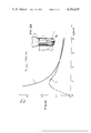
- FIG. 1A is a graph showing the relation between the path length h and the subdivision tube cross-section represented by the corresponding diameter d 2 ;
- FIG. 1B is a cross-sectional view of the bottom of a fluidized bed reactor having a reaction gas feed according to the invention, illustrating the dimensions referred to in the description of FIG. 1A.
- FIG. 2A is a graph illustrating in curve 1 the theoretical throughput according to equation (3) and, in curve 2, the experimentally determined throughput of the central jet of reaction gas as a function of subdivision tube diameter for constant aggregate open cross-section, and
- FIG. 2B is a cross-sectional view of the bottom of a fluidized bed reactor with a reaction gas feed according to the invention for indicating the dimensions involved in FIG. 2A.
- Path length h 50 mm (for FIG. 2, Curve 2)
- FIG. 2 shows the quotient of the limiting value (for laminar flow) of the throughputs respectively for the subdivided type and for the single-tube type (respectively Q d2 and Q d1 ) plotted against the subdivision tube diameter d 2 .
- the limiting throughput falls again.
- the maximum of the curve determined in practice depends upon the jet length h. For h>50 mm, the maximum value is smaller and for h ⁇ 50 mm, it is greater.
- subdivision tube diameters suitable in practice lie in the neighborhood of 2 mm.
- the lower limit region for the subdivision tube diameter is imposed in practice by expense of manufacture exceeding economic justification and by the requirement that the usable cross-section should have an economic ratio to the aggregate cross-section.
- reaction gas supply tube shiftable in the axial direction is of advantage.
- FIG. 2 Such an gas-feed nozzle 1, as known from the above-mentioned U.S. patent, except for the cross-section subdivision, is illustrated in FIG. 2.
- the outer wall 2 of the gas supply has an annular channel 3 for the carrier gas and a central tube 4 for the supply of the reaction gas.
- the central tube 4 is subdivided into a bundle of small tubes having each the diameter d 2 .
- the reaction gas and the carrier gas are introduced through the constriction 5 provided in the bottom of the fluidized bed container, into the pyrolysis furnace constituted by that container because of the heat applied to it by means not shown.
- the reaction gas supply tube 4 preferably has its cross-section subdivided over its whole length, but in the case of very long connections to the reaction gas reservoir or generator, the subdivided end portion terminating in the pipe 2, as shown in FIG. 2B, need not go all the way back to the reservoir or generator if it is long enough to smooth out all turbulence that might be present occasionally at its input end.
- the hydraulic diameter of the individual channels of the subdivided reaction gas supply tube may quite suitably be anywhere between about 1 mm and about 3.5 mm, and preferably between 1.5 mm and 3.5 mm, as is evident from FIG. 2A.
Abstract
The reaction gas throughout of the supply duct feeding gas to the bottom of a fluidized bed reactor of the kind shown in U.S. Pat. No. 4,153,004, issued May 8, 1979, is increased by providing the reaction gas supply tube in the form of a bundle of tubes of small cross-section of about 2 mm diameter. Subdivision of the supply tube into hexagonal ducts in honeycomb arrangement maximizes the useful cross-sectional area of the supply tube. With the smaller elemental tube diameters, a higher rate of flow is maintainable without loss of laminar flow behavior, which behavior is maintained in the jet issuing from the subdivided reaction gas supply duct as it flows towards the constricted entrance into the fluidized bed container while being surrounded by a sheath of inert carrier gas supplied by an annular duct surrounding the reaction gas tube. It is thus possible to increase the input of reaction gas without increasing the diameter of the jet or loss of the laminar flow characteristics necessary to prevent the reaction gas from making deposits that would interfere with the introduction of gas into the bottom of the bed.
Description
This is a division of application Ser. No. 85,780 filed Oct. 17, 1979 U.S. Pat. No. 4,259,925.
The invention relates to fluidized bed reactor of the kind in which the reaction gas is fed through a central tube around which a carrier gas is fed through a concentric annular channel, the outer walls of the annular channel being continued beyond the end of the central tube and leading to a constriction through which the reaction gas, sheathed by carrier gas enters into the conical bottom portion of a fluidized bed reactor, as disclosed in U.S. Pat. No. 4,153,004, issued May 8, 1979, owned by the Assignee of the present invention, and in particular the invention concerns a method and means for increasing the throughput of fluids, particularly gases, while maintaining laminar flow conditions, especially at rates of flow approaching the limits for laminar flow.
The fluidized bed reactor described in the abovementioned U.S. patent was developed particularly for the coating of nuclear fuel with pyrolytic carbon, hereinafter abbreviated PyC. A particular problem of such fluidized bed reactors consists in the danger that PyC growths may form at the place where the reaction gas enters into the fluidized bed, causing stoppage of the input orifices. In accordance with the disclosure of that patent, this effect is reduced by providing a reaction gas supply apparatus in which the reaction gas is introduced into the fluidized bed as a laminar central jet issuing from a supply tube that terminates below the bottom of the fluidized bed and enters into the fluidized bed without contact with the walls of the apparatus by virtue of an annular flow of carrier gas surrounding the reaction gas.
A requisite for trouble-free operation of such a fluidized bed operation is, therefore, laminar behavior of the reaction gas flow, by which it is intended to prevent the gas, prior to contact with the material to be coated, should be in contact with portions of the reactor of which the temperature is at least equal to the decomposition temperature of the reaction gas, thus leading to PyC growth on these portions of the apparatus.
Certain limits are imposed on the use of fluidized bed reactors according to U.S. Pat. No. 4,153,004 for coating operations on a technical scale, because when larger quantities of nuclear fuel are to be coated, an increase of the reaction gas supply is required which cannot readily be provided. Thus, either for a given supply tube the flow rate must be increased, or else the discharge cross-section of the supply tube must be increased. The flow through a tube cannot be increased indefinitely, because at higher throughput values at which the critical Reynolds number is reached, the character of flow changes from laminar into turbulent. With increasing cross-section of the supply tube, on the other hand, the risk of entraining solid particles into the gas supply region is increased, because with increasing discharge orifice cross-section of the supply tube, the input orifice into the fluidized bed (at the constriction mentioned above) must also be enlarged.
It has been discovered by the present invention that an extension of the operating range of fluidized bed reactors of the kind above mentioned is possible if the cross-section of the reaction gas supply tube, at least in the neighborhood of its orifice, is subdivided. It goes practically without saying that the length over which the tube cross-section is subdivided must at the very least be sufficient so that if occasional turbulence is present in the flow before reaching the subdivided section, the flow coming out of the supply tube will nevertheless be laminar.
Accordingly, it is a feature of the fluidized bed reactor of the invention that the reaction gas supply tube has cross-sectional subdivision and, in particular, it is constituted by a bundle of tubes.
In this manner, the gas throughput for a given cross-section of the supply tube can be raised in the limit region for laminar flow without the occurrence of turbulence.
If there is considered the single tube having the cross-sectional area F1 and a diameter d1, in comparison to a bundle of tubes having an aggregate open cross-sectional area F2 that is equal to the surface F1, and it is composed of z surface elements f2, each having the diameter d2, the following equations result for the fluid (gas) throughput for the single tube and for the tube bundle, these throughputs being respectively designated Q1 and Q2 : ##EQU1##
For the samd fluid in both cases and for a flow condition determined by equal Reynolds numbers (Re1 =Re2), for the two cases, it then follows that: ##STR1## Since d2 ·z is always greater than d1, for the same state of flow in the two tube arrangements, and for the same open cross-section thereof, the throughput in the tube bundle is always greater than that in the single tube. That means that the throughput for the same flow increases with decreasing d2.
This fact can be quite generally utilized in cases where it is desired to obtain the highest possible throughput with laminar flow of a fluid--regardless of the necessary power consumption. That means that cross-section subdivision, according to the invention, can always be of interest if by given constant flow behavior, particularly laminar flow in the limiting range for laminar flow, the greatest possible flow velocities are to be obtained or for a given conduit cross-section the greatest possible amounts of fluid are to be put-through per unit of time.
As an example, the transport of super-saturated liquids could be mentioned, where there is a tendency for a precipitate or bubbles to form, both of which are favored by turbulence.
In the equations set forth above, the geometric diameter tubes of circular cross-section are used for reasons of simplification, but it has been found that the relations thereby expressed nevertheless hold quite generally for any cross-sectional shape if the hydraulic or effective diameter for the cross-sectional area is substituted for the geometric diameter in the equations. For practical application of the invention, a hexagonal cross-section of the individual tubes of the tube bundle would appear to be particularly suitable, with a honeycomb arrangement of the individual tubes.
It is recognized that subdivision of the cross-section in pipes through which fluids flow are known as so-called rectifiers or grids inserts. These usually serve, however, for equalizing velocity profiles and are built into conduits for fluids without particular regard to the amount of throughput in the particular case, or to any particular state of flow (which can be basically turbulent or also laminar).
A particular object of the invention, as already mentioned above, is to obtain an increase of the reaction gas throughput in fluidized bed reactors of the type described above in which the reaction gas supply is provided through an open-ended type.
In this case, an increase of the flow through the conduit can be forced with maintenance of the required laminar flow behavior by subdivision of the cross-section for a given discharge cross-section that is small enough for the jet cross-section to remain small enough to prevent entrainment of the fluidized bed particles in the region where the gas is introduced. What is essential is that the free central jet coming out of the open end of the reaction gas supply tube, at some spacing below the fluidized bed floor, maintains all the way to its entrance into the fluidized bed, the laminar flow behavior that is imparted to it by cross-section subdivision in the supply tube. It has been found that the path length h, over which the laminar behavior is maintained after leaving the end of the supply tube, depends upon the subdivision cross-section.
The invention is further described by way of illustrative example, with reference to the annexed drawings, in which:
FIG. 1A is a graph showing the relation between the path length h and the subdivision tube cross-section represented by the corresponding diameter d2 ;
FIG. 1B is a cross-sectional view of the bottom of a fluidized bed reactor having a reaction gas feed according to the invention, illustrating the dimensions referred to in the description of FIG. 1A.
FIG. 2A is a graph illustrating in curve 1 the theoretical throughput according to equation (3) and, in curve 2, the experimentally determined throughput of the central jet of reaction gas as a function of subdivision tube diameter for constant aggregate open cross-section, and
FIG. 2B is a cross-sectional view of the bottom of a fluidized bed reactor with a reaction gas feed according to the invention for indicating the dimensions involved in FIG. 2A.
The experimentally determined curves shown in FIGS. 1 and 2 were developed under the following conditions:
Fluidized bed charge volume VB =250 ml of particles
Particle diameter dp =300 to 425 μm
Particle density ρp =1.5 g/cm3
Reynolds number of the annular jet ReRing ≠1500
Diameter of the input orifice δ=8 mm
Path length h=50 mm (for FIG. 2, Curve 2), and
Fluid=air
FIG. 1 shows the values of the maximum path length h over which laminar flow was experimentally found, plotted against the diameter of the subdivision tubes. As can be seen from this graph, h increases at small values of subdivision pipe diameter with increasing diameter, up to about d=3 mm and then remains practically constant for d>3 mm.
FIG. 2 shows the quotient of the limiting value (for laminar flow) of the throughputs respectively for the subdivided type and for the single-tube type (respectively Qd2 and Qd1) plotted against the subdivision tube diameter d2. The single tube diameter of 8 mm giving a throughput of 793.1 liters of air per hour was used as a reference.
As can be seen, curve 1 (representing equation (3) and curve 2 (experimentally determined) are approximately the same in the region of relatively little subdivision. While curve 1 runs to infinity with diminishing diameter d2, curve 2 runs through a maximum that lies at about d2 =2 mm.
With further cross-section subdivision, the limiting throughput falls again. The maximum of the curve determined in practice depends upon the jet length h. For h>50 mm, the maximum value is smaller and for h<50 mm, it is greater.
Under the conditions illustrated in the drawings, subdivision tube diameters suitable in practice lie in the neighborhood of 2 mm. The lower limit region for the subdivision tube diameter is imposed in practice by expense of manufacture exceeding economic justification and by the requirement that the usable cross-section should have an economic ratio to the aggregate cross-section.
In order to make it possible to fit the gas-feed nozzle of the fluidized bed reactor to various operating conditions, a reaction gas supply tube shiftable in the axial direction is of advantage.
Such an gas-feed nozzle 1, as known from the above-mentioned U.S. patent, except for the cross-section subdivision, is illustrated in FIG. 2. As shown, the outer wall 2 of the gas supply has an annular channel 3 for the carrier gas and a central tube 4 for the supply of the reaction gas. As shown diagrammatically at the bottom of FIG. 2B, the central tube 4 is subdivided into a bundle of small tubes having each the diameter d2. The reaction gas and the carrier gas are introduced through the constriction 5 provided in the bottom of the fluidized bed container, into the pyrolysis furnace constituted by that container because of the heat applied to it by means not shown.
The reaction gas supply tube 4 preferably has its cross-section subdivided over its whole length, but in the case of very long connections to the reaction gas reservoir or generator, the subdivided end portion terminating in the pipe 2, as shown in FIG. 2B, need not go all the way back to the reservoir or generator if it is long enough to smooth out all turbulence that might be present occasionally at its input end.
The minimum length of the subdivided portion is given by the formula
l.sub.min =0.03Re·d.sub.2
An axially shiftable reaction gas supply tube is illustrated in the above-mentioned U.S. Pat. No. 4,153,004.
Although the invention has been described with reference to particular illustrative examples, it will be understood that modifications and variations are possible within the inventive concept. Even in structures closely similar to those illustrated, for example, the hydraulic diameter of the individual channels of the subdivided reaction gas supply tube, instead of being 2 mm, may quite suitably be anywhere between about 1 mm and about 3.5 mm, and preferably between 1.5 mm and 3.5 mm, as is evident from FIG. 2A.
Claims (1)
1. A method of achieving an increased rate of laminar gas flow in the limiting range for laminar gas flow in a straight terminal portion of an open-ended duct and the length of the laminar portion of a jet issuing therefrom, which consists of providing said terminal portion of said duct with subdividing walls for subdividing the interior thereof into a plurality of separate ducts of substantially equal cross sectional area over a straight terminal portion of said duct having a length (l) which is not less than 3% of the product (Re·d2) obtained by multiplying the diameter of one of the separate ducts (d2) by the Reynolds number (Re) of the gas flow therein.
Applications Claiming Priority (2)
| Application Number | Priority Date | Filing Date | Title |
|---|---|---|---|
| DE2846160 | 1978-10-24 | ||
| DE19782846160 DE2846160A1 (en) | 1978-10-24 | 1978-10-24 | Fluidized bed reactor with open reaction gas access and method for increasing the flow rate of the laminate |
Related Parent Applications (1)
| Application Number | Title | Priority Date | Filing Date |
|---|---|---|---|
| US06/085,780 Division US4259925A (en) | 1978-10-24 | 1979-10-17 | Fluidized bed reactor |
Publications (1)
| Publication Number | Publication Date |
|---|---|
| US4354635A true US4354635A (en) | 1982-10-19 |
Family
ID=6052938
Family Applications (2)
| Application Number | Title | Priority Date | Filing Date |
|---|---|---|---|
| US06/085,780 Expired - Lifetime US4259925A (en) | 1978-10-24 | 1979-10-17 | Fluidized bed reactor |
| US06/178,785 Expired - Lifetime US4354635A (en) | 1978-10-24 | 1980-08-18 | Fluidized bed reactor with open reaction gas input and method of increasing the duct |
Family Applications Before (1)
| Application Number | Title | Priority Date | Filing Date |
|---|---|---|---|
| US06/085,780 Expired - Lifetime US4259925A (en) | 1978-10-24 | 1979-10-17 | Fluidized bed reactor |
Country Status (7)
| Country | Link |
|---|---|
| US (2) | US4259925A (en) |
| JP (1) | JPS5556831A (en) |
| BE (1) | BE879510A (en) |
| DE (1) | DE2846160A1 (en) |
| FR (1) | FR2439895A1 (en) |
| GB (1) | GB2036273B (en) |
| IT (1) | IT1125517B (en) |
Cited By (6)
| Publication number | Priority date | Publication date | Assignee | Title |
|---|---|---|---|---|
| US4795092A (en) * | 1985-11-25 | 1989-01-03 | Wet Enterprises, Inc. | Laminar flow nozzle |
| US5213260A (en) * | 1991-07-03 | 1993-05-25 | Steven Tonkinson | Nozzle for producing laminar flow |
| US5569329A (en) * | 1995-06-06 | 1996-10-29 | Carbomedics, Inc. | Fluidized bed with uniform heat distribution and multiple port nozzle |
| US6274191B1 (en) * | 1994-03-07 | 2001-08-14 | Medtronic, Inc. | Precise regulation of pyrocarbon coating |
| US6484953B2 (en) | 2001-02-06 | 2002-11-26 | Kohler Co. | Water spout with removable laminar flow cartridge |
| CN102170964A (en) * | 2008-10-03 | 2011-08-31 | 英尼奥斯欧洲有限公司 | Process for the introduction of a polymerisation catalyst into a gas-phase fluidised bed |
Families Citing this family (14)
| Publication number | Priority date | Publication date | Assignee | Title |
|---|---|---|---|---|
| DE2937652C2 (en) * | 1979-09-18 | 1981-12-10 | Kernforschungsanlage Jülich GmbH, 5170 Jülich | Nozzle for supplying gases |
| DE3007711C2 (en) * | 1980-02-29 | 1987-01-02 | Kernforschungsanlage Jülich GmbH, 5170 Jülich | Inflow unit for a fluidized bed furnace |
| US4466876A (en) * | 1981-03-17 | 1984-08-21 | Clarion Co., Ltd. | Thin layer depositing apparatus |
| JPS60501234A (en) * | 1983-04-29 | 1985-08-01 | ヒユ−ズ・エアクラフト・カンパニ− | Vertical countercurrent chemical vapor deposition reactor |
| US4732110A (en) * | 1983-04-29 | 1988-03-22 | Hughes Aircraft Company | Inverted positive vertical flow chemical vapor deposition reactor chamber |
| JPS6078707A (en) * | 1983-10-07 | 1985-05-04 | 日本碍子株式会社 | Ceramic honeycomb structure and manufacture thereof and rotary heat accumulation type ceramic heat exchange body utilizing said structure and extrusion molding die for said heat exchange body |
| US5017536A (en) * | 1984-02-03 | 1991-05-21 | Phillips Petroleum Company | Catalyst regeneration including method of introducing oxygen into fluidized bed |
| US4994239A (en) * | 1984-02-03 | 1991-02-19 | Phillips Petroleum Company | Catalyst regeneration |
| US4933149A (en) * | 1984-08-24 | 1990-06-12 | Union Carbide Chemicals And Plastics Company Inc. | Fluidized bed polymerization reactors |
| US4877587A (en) * | 1984-08-24 | 1989-10-31 | Union Carbide Chemicals And Plastics Company Inc. | Fluidized bed polymerization reactors |
| US4940007A (en) * | 1988-08-16 | 1990-07-10 | A. Ahlstrom Corporation | Fast fluidized bed reactor |
| DE19547236A1 (en) | 1995-12-18 | 1997-07-03 | Degussa | Process for the preparation of D, L-methionine or its salt |
| ATE456395T1 (en) * | 2005-07-19 | 2010-02-15 | Rec Silicon Inc | SILICON BUBBLE BED |
| FR3126231B1 (en) * | 2021-08-20 | 2023-11-17 | Safran Ceram | Device for chemical vapor deposition |
Citations (1)
| Publication number | Priority date | Publication date | Assignee | Title |
|---|---|---|---|---|
| US4153004A (en) * | 1976-03-20 | 1979-05-08 | Kernforschungsanlage Julich Gesellschaft Mit Beschrankter Haftung | Gas-feed nozzle for a pyrolytic particle coating apparatus |
Family Cites Families (9)
| Publication number | Priority date | Publication date | Assignee | Title |
|---|---|---|---|---|
| US2611685A (en) * | 1950-11-22 | 1952-09-23 | Standard Oil Dev Co | Fluid distributor for vessels |
| NL261652A (en) * | 1960-02-26 | |||
| DE1140413B (en) * | 1961-01-14 | 1962-11-29 | Schilde Maschb Ag | Treatment tube through which flow passes from bottom to top for goods that can be suspended |
| US3252823A (en) * | 1961-10-17 | 1966-05-24 | Du Pont | Process for aluminum reduction of metal halides in preparing alloys and coatings |
| US3398718A (en) * | 1965-03-10 | 1968-08-27 | Atomic Energy Commission Usa | Fluidized-bed coating apparatus |
| DE1911778A1 (en) * | 1969-03-07 | 1970-09-24 | Sigri Elektrographit Gmbh | Nozzle for fluidized bed coating reactor |
| NL7105973A (en) * | 1971-04-29 | 1972-10-31 | ||
| GB1422531A (en) * | 1972-02-07 | 1976-01-28 | English Clays Lovering Pochin | Hoses including devices for inducing streamline flow in fluids |
| US4080927A (en) * | 1976-10-06 | 1978-03-28 | General Atomic Company | Fluidized bed-gas coater apparatus |
-
1978
- 1978-10-24 DE DE19782846160 patent/DE2846160A1/en active Granted
-
1979
- 1979-10-17 US US06/085,780 patent/US4259925A/en not_active Expired - Lifetime
- 1979-10-19 BE BE0/197719A patent/BE879510A/en not_active IP Right Cessation
- 1979-10-19 IT IT26645/79A patent/IT1125517B/en active
- 1979-10-23 FR FR7926210A patent/FR2439895A1/en active Granted
- 1979-10-24 JP JP13652779A patent/JPS5556831A/en active Pending
- 1979-10-24 GB GB7936944A patent/GB2036273B/en not_active Expired
-
1980
- 1980-08-18 US US06/178,785 patent/US4354635A/en not_active Expired - Lifetime
Patent Citations (1)
| Publication number | Priority date | Publication date | Assignee | Title |
|---|---|---|---|---|
| US4153004A (en) * | 1976-03-20 | 1979-05-08 | Kernforschungsanlage Julich Gesellschaft Mit Beschrankter Haftung | Gas-feed nozzle for a pyrolytic particle coating apparatus |
Cited By (8)
| Publication number | Priority date | Publication date | Assignee | Title |
|---|---|---|---|---|
| US4795092A (en) * | 1985-11-25 | 1989-01-03 | Wet Enterprises, Inc. | Laminar flow nozzle |
| US5213260A (en) * | 1991-07-03 | 1993-05-25 | Steven Tonkinson | Nozzle for producing laminar flow |
| US6274191B1 (en) * | 1994-03-07 | 2001-08-14 | Medtronic, Inc. | Precise regulation of pyrocarbon coating |
| US5569329A (en) * | 1995-06-06 | 1996-10-29 | Carbomedics, Inc. | Fluidized bed with uniform heat distribution and multiple port nozzle |
| US5891517A (en) * | 1995-06-06 | 1999-04-06 | Sulzer Carbomedics Inc. | Fluidized bed with uniform heat distribution and multiple port nozzle |
| US6484953B2 (en) | 2001-02-06 | 2002-11-26 | Kohler Co. | Water spout with removable laminar flow cartridge |
| CN102170964A (en) * | 2008-10-03 | 2011-08-31 | 英尼奥斯欧洲有限公司 | Process for the introduction of a polymerisation catalyst into a gas-phase fluidised bed |
| CN102170964B (en) * | 2008-10-03 | 2014-07-16 | 英尼奥斯欧洲有限公司 | Process for the introduction of a polymerisation catalyst into a gas-phase fluidised bed |
Also Published As
| Publication number | Publication date |
|---|---|
| IT1125517B (en) | 1986-05-14 |
| GB2036273A (en) | 1980-06-25 |
| FR2439895B1 (en) | 1983-01-28 |
| FR2439895A1 (en) | 1980-05-23 |
| JPS5556831A (en) | 1980-04-26 |
| GB2036273B (en) | 1983-08-17 |
| DE2846160A1 (en) | 1980-05-08 |
| BE879510A (en) | 1980-02-15 |
| DE2846160C2 (en) | 1987-12-10 |
| US4259925A (en) | 1981-04-07 |
| IT7926645A0 (en) | 1979-10-19 |
Similar Documents
| Publication | Publication Date | Title |
|---|---|---|
| US4354635A (en) | Fluidized bed reactor with open reaction gas input and method of increasing the duct | |
| JP2664670B2 (en) | Equipment for producing syngas | |
| US3566961A (en) | Tubular reactor for carrying out endothermic and exothermic reactions with forced circulation | |
| US4795547A (en) | Process for contacting particulate solids with a fluid | |
| EP2055674B1 (en) | Apparatus for producing trichlorosilane and method for producing thrichlorosilane | |
| US4245693A (en) | Waste heat recovery | |
| GB1092883A (en) | Improvements in and relating to the manufacture of oxides | |
| JPH0415839B2 (en) | ||
| US3694169A (en) | Low pressure-drop catalytic reactor | |
| US7021870B2 (en) | Device for the transport of granular solid particles with a controlled flow rate | |
| US3753658A (en) | Carbon black apparatus | |
| CA1201577A (en) | Method and apparatus to improve circulation control in fluidized systems | |
| US2868627A (en) | Apparatus for carbon monoxide hydrogenation | |
| US3085865A (en) | Apparatus for the oxidation of metal powders | |
| DE1601162C3 (en) | Tube bundle reactor for carrying out endothermic and exothermic reactions with forced circulation of the heat transfer medium | |
| US5362453A (en) | Reformer for the generation of synthesis gas | |
| US4338187A (en) | Solids feeding device and system | |
| US4387120A (en) | Gas injector for fluidized bed furnace | |
| WO1985004820A1 (en) | Reactor | |
| US4407230A (en) | Gas-feed nozzle for a pyrolytic particle coating apparatus | |
| GB2125710A (en) | A two-material atomisation nozzle | |
| GB2095123A (en) | Apparatus for introducing a gas into a liquid or a liquid-solids mixture | |
| Whitehead et al. | Fluidization studies in large gas—solid systems Part V. Long and short term pressure instabilities | |
| US2492349A (en) | Carrying out catalytic reactions | |
| US2149300A (en) | Distribution and temperature control in chemical reactions |
Legal Events
| Date | Code | Title | Description |
|---|---|---|---|
| STCF | Information on status: patent grant |
Free format text: PATENTED CASE |