US4358697A - Two-pole permanent magnet synchronous motor rotor - Google Patents
Two-pole permanent magnet synchronous motor rotor Download PDFInfo
- Publication number
- US4358697A US4358697A US06/294,362 US29436281A US4358697A US 4358697 A US4358697 A US 4358697A US 29436281 A US29436281 A US 29436281A US 4358697 A US4358697 A US 4358697A
- Authority
- US
- United States
- Prior art keywords
- slots
- rotor
- pair
- magnetic
- magnet
- Prior art date
- Legal status (The legal status is an assumption and is not a legal conclusion. Google has not performed a legal analysis and makes no representation as to the accuracy of the status listed.)
- Expired - Lifetime
Links
Images
Classifications
-
- H—ELECTRICITY
- H02—GENERATION; CONVERSION OR DISTRIBUTION OF ELECTRIC POWER
- H02K—DYNAMO-ELECTRIC MACHINES
- H02K1/00—Details of the magnetic circuit
- H02K1/06—Details of the magnetic circuit characterised by the shape, form or construction
- H02K1/22—Rotating parts of the magnetic circuit
- H02K1/27—Rotor cores with permanent magnets
- H02K1/2706—Inner rotors
- H02K1/272—Inner rotors the magnetisation axis of the magnets being perpendicular to the rotor axis
- H02K1/274—Inner rotors the magnetisation axis of the magnets being perpendicular to the rotor axis the rotor consisting of two or more circumferentially positioned magnets
- H02K1/2753—Inner rotors the magnetisation axis of the magnets being perpendicular to the rotor axis the rotor consisting of two or more circumferentially positioned magnets the rotor consisting of magnets or groups of magnets arranged with alternating polarity
- H02K1/276—Magnets embedded in the magnetic core, e.g. interior permanent magnets [IPM]
- H02K1/2766—Magnets embedded in the magnetic core, e.g. interior permanent magnets [IPM] having a flux concentration effect
-
- H—ELECTRICITY
- H02—GENERATION; CONVERSION OR DISTRIBUTION OF ELECTRIC POWER
- H02K—DYNAMO-ELECTRIC MACHINES
- H02K21/00—Synchronous motors having permanent magnets; Synchronous generators having permanent magnets
- H02K21/46—Motors having additional short-circuited winding for starting as an asynchronous motor
Definitions
- This invention relates to permanent magnet synchronous motors, and more particularly to an improved rotor construction for two-pole permanent magnet rotors.
- Synchronous reluctance motors may be generally thought of as induction motors whose rotors have been provided with flux barriers which cause the magnetic reluctance of the rotor to vary with rotor orientation, in effect providing magnetic poles which "follow" the rotating magnetic field produced by the stator windings. Examples of such synchronous reluctance rotors are illustrated in U.S. Pat. No. 3,652,885--Honsinger and U.S. Pat. No. 3,862,446--Hilgeman et al.
- the flux barriers of these motors are constituted by axial slots extending through the stacked rotor laminations, which are filled with a nonmagnetic, high-reluctance material such as die cast aluminum.
- Such motors are typically provided with a set of axial rotor bar slots near the peripheries thereof, much in the manner of ordinary induction motors.
- the rare earth magnets which are now often used in such rotors are very expensive, which makes it desirable to limit the number and volume of the magnets.
- the cost of the magnets which makes it desirable to utilize magnets of a common size and shape.
- Another object is to provide a two-pole permanent magnet synchronous motor rotor which exhibits improved torque charcteristics and makes better use of magnetic materials than those herein before known.
- Yet another object is to achieve an advantageous rotor design utilizing magnets of a common size and shape.
- the foregoing objects are achieved by providing a plurality of laminations which are stacked together to form a rotor body.
- the laminations are provided with openings which align with one another to define passages ("slots") extending axially through the rotor body.
- the slots which receive the magnets are arrayed generally tangentially about the rotor shaft, and separated along a first axis by magnetic bridges formed integrally with the laminations.
- Another group of slots lying along a common diametrical line but at opposite sides of the rotor, extend outwardly to a point near the edge of the rotor, being interleaved with the rotor bar openings.
- the latter slots extend radially inwardly to a point between adjacent magnet slots and define two more pairs of magnetic bridges, also formed integrally with the laminations but lying at an acute angle with the quadrature axis.
- the innermost ends of the latter slots are generally triangular, being formed by the convergence of the slot sidewalls and the triangular opening formed thereby filled with cast aluminum.
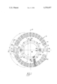
- the rotor cross section which is shown in the FIGURE illustrates a rotor body 10 formed of a stack of individual laminations. Each lamination has a pattern of openings punched therein, so that when the laminations are stacked to form a rotor core the openings align to form axially-directed passages or "slots."
- a first set of slots such as shown at 12 extend about the periphery of the rotor and contain conductive rotor bars 14, as is conventional in induction motor design.
- the rotor bars 14 may be formed of any appropriate conductive metal and may be driven into the rotor, or cast in place. As will be further explained hereinafter, it is contemplated that the rotor bars will be formed of aluminum, and die cast in the rotor in a single operation.
- a pair of symmetrically-disposed holes 16 receive rivets which are deformed after the stack of laminations is compressed and hold the laminations together in the usual manner.
- a central opening 18 is provided for receiving a rotor shaft upon which the rotor will be journaled.
- the shaft may be formed of a magnetic material. The use of magnetic metal for rotor shafts is of great assistance in minimizing the cost of motor construction.
- a first pair of arcuate slots 20, 21 are formed at one side of the rotor body and a similar, second pair of slots 22, 23 formed on the other side so that the arrangement is symmetrical about a diametrical line Q.
- the first and second pairs of slots are spaced apart by short magnetic bridges 24, 25 respectively.
- the bridges serve to mechanically connect the rotor portion lying radially outside the magnet slots with the portion lying radially within the slots to resist the centrifugal forces which arise during motor operation.
- a third pair of magnet slots 26, 27 is disposed along diametrical line Q, which corresponds to the quadrature axis of the rotor, so that they extend radially outwardly.
- These magnets are preferably twice as thick as the magnets disposed in tangential slots 20-23.
- the outermost ends of the magnet slots terminate at a point close to the edge of the rotor periphery, leaving only a thin bridge of lamination material 28 which is sufficient to withstand the forces which arise during motor operation, without providing a significant flux leakage path.
- a small amount of flux 29 is necessarily "short circuited" in the rotor material; but owing to the small width of the magnetic path the material saturates readily and therefore does not divert appreciable amounts of magnetic flux from the air gap about the rotor.
- the magnets in the third set of magnet slots are generally interleaved with the rotor bars 14 although the magnets therein, generally indicated at 30, do not conduct electric current and do not contritube to motor torque under non-synchronous running conditions as do the rotor bars.
- the opposing sides of the third set of magnet slots converge near the inner ends thereof, so that a generally triangular void is formed.
- the slot edges preferably extend parallel to the nearby ends of magnet slots 21, 23 so that a pair of magnetic bridges 35 and 36 are formed symmetrically about line Q at the inner end of the right-hand radial magnet slot, extending at an acute angle to line Q.
- Asymmetrical construction is utilized for the left-hand magnet slot.
- a "north" pole is constituted at the top center of the rotor, along line D which represents the direct axis of the stator field during synchronous operation.
- a south pole is effectively produced at the lower center of the rotor in the illustration, also along the direct axis.
- Rotors designed in accordance with the teachings of the present invention operate in accordance with conventional principles of synchronous motor operation.
- the stator field effectively rotates about the rotor, the "slip" inducing current into rotor bars 14 which in turn produce torque to accelerate the rotor to a speed approching synchronous speed.
- the flux pattern produced by the permanent magnets then locks into synchronism with the rotating stator flux field, and continues to rotate in synchronism therewith.
- Lines of flux are provided by the permanent magnets in the first and second pairs of slots which surround the rotor shaft. These lines of flux extend through the magnetic rotor shaft (not present in the illustration), and outwardly across the motor air gap.
- a negligible amount of flux is "short circuited" through the magnetic bridges which connect the radially inner and outer parts of the lamination, but owing to the narrow nature of the bridges they soon saturate and become a substantially high-reluctance paths. Accordingly, the flux lines for the most part extend radially outwardly from the magnet surfaces, through the rotor teeth between the rotor bars, across the air gap and ultimately return by a similar path. It will be noted that the radially-extending magnets disposed in the third set of magnet slots 26, 27 also serve as a barrier to prevent the lines of flux from re-entering the rotor body prematurely.
- the adjacent ends of slots 20, 21 and also of slots 22, 23 extend past the edges of the rectangular magnets therein, in order to make bridges 24 and 25 as narrow as possible.
- the small voids at the ends of these slots, and the voids occurring at the "knee" of the slots, between the magnets placed therein, are also filled with die-cast aluminum.
- the material which forms rotor bars 14 and fills the voids about the magnets is injected into the rotor body in a single step. The die cast material is forced into the voids about the magnets and locks them into place, as well as providing a low-reluctance magnetic path which discourages stray lines of flux.
- the voids in the magnet slots could be filled with other materials, either solid or a hardenable fluid such as epoxy resin.
- the radially-extending magnets are disposed upon the Q-axis and the adjacent magnetic bridges are positioned off the Q-axis, at an acute angle thereto, the mechanical strength of the rotor is improved and the susceptibility of the punchings to damage during manufacture is greatly lessened.
- the permanent magnets are of the rare earth variety.
- the magnets are magnetized transversely as shown so that similar poles face in the same direction, e.g., upward in the FIGURE. This gives rise to a symmetrical flux pattern partially illustrated by flux lines 32 and 34, producing two magnetic poles oriented upon the D axis.
- Magnets utilizing materials such as samarium cobalt (SmCo5) are preferred in the illustrated embodiment.
- Such magnets exhibit a very high coercive force, so that the magnets can only be demagnetized by extremely high operating temperatures, on the order of 200° celsius, or by extremely high external magnetic fields which ordinarily result only from accidental overvoltage conditions.
- the magnets are ordinarily sintered and pressed into a flat, rectangular cross section product which while quite dense is rather brittle and subject to damage unless skillfully handled.
- Alnico-type magnets may also be used although they have the disadvantge of a relatively low coercivity compared to ferrite and samarium cobalt magnets.
- rare-earth magnets cost considerably more than other, similar permanent magnets so that to be economically feasible they require a rotor design which makes optimum use of the volume of magnetic material.
Abstract
Description
Claims (7)
Priority Applications (3)
| Application Number | Priority Date | Filing Date | Title |
|---|---|---|---|
| US06/294,362 US4358697A (en) | 1981-08-19 | 1981-08-19 | Two-pole permanent magnet synchronous motor rotor |
| DE19828221075U DE8221075U1 (en) | 1981-08-19 | 1982-07-23 | PERMANENT MAGNETIC RUNNER FOR A SYNCHRONOUS MACHINE |
| EP82106748A EP0072460A1 (en) | 1981-08-19 | 1982-07-26 | Permanent-magnet excited rotor for a synchronous machine |
Applications Claiming Priority (1)
| Application Number | Priority Date | Filing Date | Title |
|---|---|---|---|
| US06/294,362 US4358697A (en) | 1981-08-19 | 1981-08-19 | Two-pole permanent magnet synchronous motor rotor |
Publications (1)
| Publication Number | Publication Date |
|---|---|
| US4358697A true US4358697A (en) | 1982-11-09 |
Family
ID=23133083
Family Applications (1)
| Application Number | Title | Priority Date | Filing Date |
|---|---|---|---|
| US06/294,362 Expired - Lifetime US4358697A (en) | 1981-08-19 | 1981-08-19 | Two-pole permanent magnet synchronous motor rotor |
Country Status (1)
| Country | Link |
|---|---|
| US (1) | US4358697A (en) |
Cited By (62)
| Publication number | Priority date | Publication date | Assignee | Title |
|---|---|---|---|---|
| US4480207A (en) * | 1982-12-27 | 1984-10-30 | General Electric Company | Permanent magnet rotor and method of making same |
| US4486679A (en) * | 1983-10-28 | 1984-12-04 | General Electric Company | Permanent magnet rotor and method of making same |
| US4502752A (en) * | 1982-11-08 | 1985-03-05 | General Scanning, Inc. | Resonant actuator for optical scanning |
| US4510680A (en) * | 1982-12-27 | 1985-04-16 | General Electric Company | Method of making a permanent magnet rotor |
| US4516046A (en) * | 1981-08-06 | 1985-05-07 | Cem Compagnie Electro-Mecanique | Continuous current electric machine with cylindrical air gap and permanent magnet pole piece |
| US4559463A (en) * | 1983-07-27 | 1985-12-17 | Hitachi, Ltd. | Large surface area permanent magnet type rotary electrical machine |
| US4570333A (en) * | 1983-10-28 | 1986-02-18 | General Electric Company | Method of making a permanent magnet rotor |
| US4883999A (en) * | 1988-08-15 | 1989-11-28 | Pacific Scientific Company | Polyphase electronically commutated reluctance motor |
| US4922152A (en) * | 1988-07-27 | 1990-05-01 | Siemens Energy & Automation, Inc. | Synchronous machine rotor lamination |
| US5097166A (en) * | 1990-09-24 | 1992-03-17 | Reuland Electric | Rotor lamination for an AC permanent magnet synchronous motor |
| US5191255A (en) * | 1991-02-19 | 1993-03-02 | Magnetospheric Power Corp. Ltd. | Electromagnetic motor |
| US5565752A (en) * | 1993-12-22 | 1996-10-15 | Wisconsin Alumni Research Foundation | Method and apparatus for transducerless position and velocity estimation in drives for AC machines |
| US5672926A (en) * | 1995-02-21 | 1997-09-30 | Siemens Aktiengesellschaft | Hybrid-energized electric machine |
| US5731647A (en) * | 1995-02-21 | 1998-03-24 | Siemens Aktiengesellschaft | Hybrid-energized synchronous electric machine |
| US5798596A (en) * | 1996-07-03 | 1998-08-25 | Pacific Scientific Company | Permanent magnet motor with enhanced inductance |
| US5818140A (en) * | 1995-07-11 | 1998-10-06 | Vagati; Alfredo | Synchronous reluctance electrical motor having a low torque-ripple design |
| US5838086A (en) * | 1994-07-27 | 1998-11-17 | Parvex | Synchronous motor with permanent magnets included in a rotor |
| EP0917272A1 (en) * | 1997-09-29 | 1999-05-19 | Fujitsu General Limited | Permanent magnet rotor type electric motor |
| US5945760A (en) * | 1995-05-31 | 1999-08-31 | Matsushita Electric Industrial Co., Ltd. | Motor with built-in permanent magnets |
| US6029336A (en) * | 1994-04-18 | 2000-02-29 | General Electric Company | Method of fabricating a permanent magnet line start motor having magnets outside the starting cage |
| US6144131A (en) * | 1995-06-07 | 2000-11-07 | General Electric Company | Dynamoelectric machine rotor having interleaved laminations and method for forming |
| US20030011266A1 (en) * | 2001-06-21 | 2003-01-16 | Ikuro Morita | Embedded permanent magnet type induction motor which allows coil embedding work to be easily performed |
| US6847143B1 (en) * | 1999-03-22 | 2005-01-25 | Valeo Equipements Electriques Moteur | Rotary electrical machine having magnet arrangements with magnets of different compositions |
| US20050275302A1 (en) * | 2004-06-14 | 2005-12-15 | Rahman Khwaja M | Rotor magnet placement in interior permanent magnet machines |
| US20070103023A1 (en) * | 2005-11-04 | 2007-05-10 | Canopy Tecnologies, Llc | Method of compressing lamination stacks for permanent magnet rotor |
| US20080246373A1 (en) * | 2007-04-05 | 2008-10-09 | Calnetix, Inc. | Generating electromagnetic forces |
| US20080250789A1 (en) * | 2007-04-16 | 2008-10-16 | Turbogenix, Inc. | Fluid flow in a fluid expansion system |
| US20080252078A1 (en) * | 2007-04-16 | 2008-10-16 | Turbogenix, Inc. | Recovering heat energy |
| US20080252077A1 (en) * | 2007-04-16 | 2008-10-16 | Calnetix, Inc. | Generating energy from fluid expansion |
| WO2009094541A2 (en) * | 2008-01-25 | 2009-07-30 | Calnetix, Inc. | Generating electromagnetic forces with flux feedback control |
| US20090278416A1 (en) * | 2005-12-21 | 2009-11-12 | Daikin Industries, Ltd. | Motor and compressor |
| US20100090556A1 (en) * | 2008-10-09 | 2010-04-15 | Calnetix, Inc. | High-aspect ratio homopolar magnetic actuator |
| US20100117627A1 (en) * | 2008-11-07 | 2010-05-13 | Calnetix, Inc. | Measuring linear velocity |
| US20100156228A1 (en) * | 2006-08-16 | 2010-06-24 | Kalluf Flavio J H | Synchronous machine and a process of manufacturing a synchronous machine |
| US20100301840A1 (en) * | 2009-05-29 | 2010-12-02 | Calnetix, Inc. | Measuring the position of an object |
| US20110101905A1 (en) * | 2009-11-02 | 2011-05-05 | Calnetix, Inc. | Generating electromagnetic forces in large air gaps |
| US20110234037A1 (en) * | 2007-10-26 | 2011-09-29 | Nova Torque, Inc. | Stator and rotor-stator structures for electrodynamic machines |
| JP2012143034A (en) * | 2010-12-28 | 2012-07-26 | Mitsubishi Electric Corp | Induction motor, compressor, and refrigeration cycle device |
| WO2013020310A1 (en) * | 2011-08-05 | 2013-02-14 | 珠海格力电器股份有限公司 | Motor rotor and motor having same |
| CN101771315B (en) * | 2008-12-09 | 2013-05-29 | 通用汽车环球科技运作公司 | Method and apparatus for permanent magnet machine with segmented ferrite magnets |
| US8482174B2 (en) | 2011-05-26 | 2013-07-09 | Calnetix Technologies, Llc | Electromagnetic actuator |
| US20130326855A1 (en) * | 2011-02-17 | 2013-12-12 | Cern - European Organization For Nuclear Research | System and Method for Positioning and Fixing Objects Relative to Each Other |
| US20140021821A1 (en) * | 2011-04-08 | 2014-01-23 | Grundfos Management A/S | Rotor |
| US8739538B2 (en) | 2010-05-28 | 2014-06-03 | General Electric Company | Generating energy from fluid expansion |
| US8796894B2 (en) | 2010-01-06 | 2014-08-05 | Calnetix Technologies, L.L.C. | Combination radial/axial electromagnetic actuator |
| US8847451B2 (en) | 2010-03-23 | 2014-09-30 | Calnetix Technologies, L.L.C. | Combination radial/axial electromagnetic actuator with an improved axial frequency response |
| US8928198B2 (en) | 2011-02-28 | 2015-01-06 | Uqm Technologies Inc. | Brushless PM machine construction enabling low coercivity magnets |
| US8984884B2 (en) | 2012-01-04 | 2015-03-24 | General Electric Company | Waste heat recovery systems |
| US9018778B2 (en) | 2012-01-04 | 2015-04-28 | General Electric Company | Waste heat recovery system generator varnishing |
| US9024494B2 (en) | 2013-01-07 | 2015-05-05 | Calnetix Technologies, Llc | Mechanical backup bearing arrangement for a magnetic bearing system |
| US9024460B2 (en) | 2012-01-04 | 2015-05-05 | General Electric Company | Waste heat recovery system generator encapsulation |
| US9093874B2 (en) | 2004-10-25 | 2015-07-28 | Novatorque, Inc. | Sculpted field pole members and methods of forming the same for electrodynamic machines |
| CN105745820A (en) * | 2013-11-20 | 2016-07-06 | 日立汽车系统株式会社 | Rotary electric machine and electric vehicle provided with same |
| US9450472B2 (en) | 2010-06-14 | 2016-09-20 | Black & Decker, Inc. | Rotor assembly for brushless motor for a power tool |
| US9502933B2 (en) | 2011-08-05 | 2016-11-22 | Gree Electric Appliances, Inc. Of Zhuhai | Permanent magnet synchronous electric machine |
| US9502934B2 (en) | 2011-08-05 | 2016-11-22 | Gree Electric Appliances, Inc. Of Zhuhai | Motor rotor and motor having same |
| US9515526B2 (en) | 2011-08-05 | 2016-12-06 | Gree Electric Appliances, Inc. Of Zhuhai | Motor and rotor thereof |
| US9531236B2 (en) | 2011-06-02 | 2016-12-27 | Calnetix Technologies, Llc | Arrangement of axial and radial electromagnetic actuators |
| US9559565B2 (en) | 2013-08-22 | 2017-01-31 | Calnetix Technologies, Llc | Homopolar permanent-magnet-biased action magnetic bearing with an integrated rotational speed sensor |
| US9683601B2 (en) | 2013-03-14 | 2017-06-20 | Calnetix Technologies, Llc | Generating radial electromagnetic forces |
| WO2018099632A1 (en) * | 2016-11-30 | 2018-06-07 | Ebm-Papst Mulfingen Gmbh & Co. Kg | Rotor for an lspm electric motor |
| US20220077732A1 (en) * | 2020-09-07 | 2022-03-10 | ElectromagnetiX LLC | Motor using permanent magnets and induction windings for use with an electrical submersible pump |
Citations (5)
| Publication number | Priority date | Publication date | Assignee | Title |
|---|---|---|---|---|
| US3492520A (en) * | 1967-02-14 | 1970-01-27 | Westinghouse Electric Corp | Permanent magnet rotor |
| US3840763A (en) * | 1973-07-09 | 1974-10-08 | Gen Electric | Low flux density permanent magnet field configuration |
| US4127786A (en) * | 1976-03-01 | 1978-11-28 | Siemens Aktiengesellschaft | Synchronous machine with inner rotor, excited by permanent magnets |
| US4139790A (en) * | 1977-08-31 | 1979-02-13 | Reliance Electric Company | Direct axis aiding permanent magnets for a laminated synchronous motor rotor |
| US4324996A (en) * | 1979-07-11 | 1982-04-13 | Siemens Aktiengesellschaft | Interior rotor for an electric machine |
-
1981
- 1981-08-19 US US06/294,362 patent/US4358697A/en not_active Expired - Lifetime
Patent Citations (5)
| Publication number | Priority date | Publication date | Assignee | Title |
|---|---|---|---|---|
| US3492520A (en) * | 1967-02-14 | 1970-01-27 | Westinghouse Electric Corp | Permanent magnet rotor |
| US3840763A (en) * | 1973-07-09 | 1974-10-08 | Gen Electric | Low flux density permanent magnet field configuration |
| US4127786A (en) * | 1976-03-01 | 1978-11-28 | Siemens Aktiengesellschaft | Synchronous machine with inner rotor, excited by permanent magnets |
| US4139790A (en) * | 1977-08-31 | 1979-02-13 | Reliance Electric Company | Direct axis aiding permanent magnets for a laminated synchronous motor rotor |
| US4324996A (en) * | 1979-07-11 | 1982-04-13 | Siemens Aktiengesellschaft | Interior rotor for an electric machine |
Cited By (91)
| Publication number | Priority date | Publication date | Assignee | Title |
|---|---|---|---|---|
| US4516046A (en) * | 1981-08-06 | 1985-05-07 | Cem Compagnie Electro-Mecanique | Continuous current electric machine with cylindrical air gap and permanent magnet pole piece |
| US4502752A (en) * | 1982-11-08 | 1985-03-05 | General Scanning, Inc. | Resonant actuator for optical scanning |
| US4480207A (en) * | 1982-12-27 | 1984-10-30 | General Electric Company | Permanent magnet rotor and method of making same |
| US4510680A (en) * | 1982-12-27 | 1985-04-16 | General Electric Company | Method of making a permanent magnet rotor |
| US4559463A (en) * | 1983-07-27 | 1985-12-17 | Hitachi, Ltd. | Large surface area permanent magnet type rotary electrical machine |
| US4486679A (en) * | 1983-10-28 | 1984-12-04 | General Electric Company | Permanent magnet rotor and method of making same |
| US4570333A (en) * | 1983-10-28 | 1986-02-18 | General Electric Company | Method of making a permanent magnet rotor |
| US4922152A (en) * | 1988-07-27 | 1990-05-01 | Siemens Energy & Automation, Inc. | Synchronous machine rotor lamination |
| US4883999A (en) * | 1988-08-15 | 1989-11-28 | Pacific Scientific Company | Polyphase electronically commutated reluctance motor |
| US5097166A (en) * | 1990-09-24 | 1992-03-17 | Reuland Electric | Rotor lamination for an AC permanent magnet synchronous motor |
| US5191255A (en) * | 1991-02-19 | 1993-03-02 | Magnetospheric Power Corp. Ltd. | Electromagnetic motor |
| US5565752A (en) * | 1993-12-22 | 1996-10-15 | Wisconsin Alumni Research Foundation | Method and apparatus for transducerless position and velocity estimation in drives for AC machines |
| US6029336A (en) * | 1994-04-18 | 2000-02-29 | General Electric Company | Method of fabricating a permanent magnet line start motor having magnets outside the starting cage |
| US5838086A (en) * | 1994-07-27 | 1998-11-17 | Parvex | Synchronous motor with permanent magnets included in a rotor |
| US5672926A (en) * | 1995-02-21 | 1997-09-30 | Siemens Aktiengesellschaft | Hybrid-energized electric machine |
| US5731647A (en) * | 1995-02-21 | 1998-03-24 | Siemens Aktiengesellschaft | Hybrid-energized synchronous electric machine |
| US5945760A (en) * | 1995-05-31 | 1999-08-31 | Matsushita Electric Industrial Co., Ltd. | Motor with built-in permanent magnets |
| US6144131A (en) * | 1995-06-07 | 2000-11-07 | General Electric Company | Dynamoelectric machine rotor having interleaved laminations and method for forming |
| US5818140A (en) * | 1995-07-11 | 1998-10-06 | Vagati; Alfredo | Synchronous reluctance electrical motor having a low torque-ripple design |
| US5798596A (en) * | 1996-07-03 | 1998-08-25 | Pacific Scientific Company | Permanent magnet motor with enhanced inductance |
| US6025667A (en) * | 1997-09-29 | 2000-02-15 | Fujitsu General Limited | Permanent magnet rotor type electric motor with different permanent magnet materials |
| AU747000B2 (en) * | 1997-09-29 | 2002-05-09 | Fujitsu General Limited | Permanent magnet rotor type electric motor |
| EP0917272A1 (en) * | 1997-09-29 | 1999-05-19 | Fujitsu General Limited | Permanent magnet rotor type electric motor |
| US6847143B1 (en) * | 1999-03-22 | 2005-01-25 | Valeo Equipements Electriques Moteur | Rotary electrical machine having magnet arrangements with magnets of different compositions |
| US20030011266A1 (en) * | 2001-06-21 | 2003-01-16 | Ikuro Morita | Embedded permanent magnet type induction motor which allows coil embedding work to be easily performed |
| US6727624B2 (en) * | 2001-06-21 | 2004-04-27 | Sumitomo Heavy Industries, Ltd. | Embedded permanent magnet type induction motor which allows coil embedding work to be easily performed |
| US20050275302A1 (en) * | 2004-06-14 | 2005-12-15 | Rahman Khwaja M | Rotor magnet placement in interior permanent magnet machines |
| US7474029B2 (en) * | 2004-06-14 | 2009-01-06 | General Motors Corporation | Rotor magnet placement in interior permanent magnet machines |
| US9093874B2 (en) | 2004-10-25 | 2015-07-28 | Novatorque, Inc. | Sculpted field pole members and methods of forming the same for electrodynamic machines |
| US20070103023A1 (en) * | 2005-11-04 | 2007-05-10 | Canopy Tecnologies, Llc | Method of compressing lamination stacks for permanent magnet rotor |
| US7358637B2 (en) | 2005-11-04 | 2008-04-15 | Canopy Technologies, Llc | Method of compressing lamination stacks for permanent magnet rotor |
| US8072110B2 (en) * | 2005-12-21 | 2011-12-06 | Daikin Industries, Ltd. | Motor and compressor |
| US20090278416A1 (en) * | 2005-12-21 | 2009-11-12 | Daikin Industries, Ltd. | Motor and compressor |
| US7923882B2 (en) * | 2006-08-16 | 2011-04-12 | Whirlpool S.A. | Synchronous machine and a process of manufacturing a synchronous machine |
| US20100156228A1 (en) * | 2006-08-16 | 2010-06-24 | Kalluf Flavio J H | Synchronous machine and a process of manufacturing a synchronous machine |
| US20080246373A1 (en) * | 2007-04-05 | 2008-10-09 | Calnetix, Inc. | Generating electromagnetic forces |
| US7557480B2 (en) * | 2007-04-05 | 2009-07-07 | Calnetix, Inc. | Communicating magnetic flux across a gap with a rotating body |
| US20100320764A1 (en) * | 2007-04-16 | 2010-12-23 | Calnetix Power Solutions, Inc. | Recovering heat energy |
| US20080252077A1 (en) * | 2007-04-16 | 2008-10-16 | Calnetix, Inc. | Generating energy from fluid expansion |
| US7638892B2 (en) | 2007-04-16 | 2009-12-29 | Calnetix, Inc. | Generating energy from fluid expansion |
| US20080250789A1 (en) * | 2007-04-16 | 2008-10-16 | Turbogenix, Inc. | Fluid flow in a fluid expansion system |
| US8146360B2 (en) | 2007-04-16 | 2012-04-03 | General Electric Company | Recovering heat energy |
| US20080252078A1 (en) * | 2007-04-16 | 2008-10-16 | Turbogenix, Inc. | Recovering heat energy |
| US7841306B2 (en) | 2007-04-16 | 2010-11-30 | Calnetix Power Solutions, Inc. | Recovering heat energy |
| US8839622B2 (en) | 2007-04-16 | 2014-09-23 | General Electric Company | Fluid flow in a fluid expansion system |
| US8072106B2 (en) * | 2007-10-26 | 2011-12-06 | Novatorque, Inc. | Stator and rotor-stator structures for electrodynamic machines |
| US20110234037A1 (en) * | 2007-10-26 | 2011-09-29 | Nova Torque, Inc. | Stator and rotor-stator structures for electrodynamic machines |
| WO2009094541A2 (en) * | 2008-01-25 | 2009-07-30 | Calnetix, Inc. | Generating electromagnetic forces with flux feedback control |
| WO2009094541A3 (en) * | 2008-01-25 | 2009-10-29 | Calnetix, Inc. | Generating electromagnetic forces with flux feedback control |
| US20090201111A1 (en) * | 2008-01-25 | 2009-08-13 | Calnetix, Inc. | Generating electromagnetic forces with flux feedback control |
| US8102088B2 (en) | 2008-01-25 | 2012-01-24 | Calnetix Technologies, L.L.C. | Generating electromagnetic forces with flux feedback control |
| US8169118B2 (en) | 2008-10-09 | 2012-05-01 | Calnetix Technologies, L.L.C. | High-aspect-ratio homopolar magnetic actuator |
| US20100090556A1 (en) * | 2008-10-09 | 2010-04-15 | Calnetix, Inc. | High-aspect ratio homopolar magnetic actuator |
| US20100117627A1 (en) * | 2008-11-07 | 2010-05-13 | Calnetix, Inc. | Measuring linear velocity |
| US8183854B2 (en) | 2008-11-07 | 2012-05-22 | Calnetix Technologies, L.L.C. | Measuring linear velocity |
| CN101771315B (en) * | 2008-12-09 | 2013-05-29 | 通用汽车环球科技运作公司 | Method and apparatus for permanent magnet machine with segmented ferrite magnets |
| US20100301840A1 (en) * | 2009-05-29 | 2010-12-02 | Calnetix, Inc. | Measuring the position of an object |
| US8564281B2 (en) | 2009-05-29 | 2013-10-22 | Calnetix Technologies, L.L.C. | Noncontact measuring of the position of an object with magnetic flux |
| US8378543B2 (en) | 2009-11-02 | 2013-02-19 | Calnetix Technologies, L.L.C. | Generating electromagnetic forces in large air gaps |
| US20110101905A1 (en) * | 2009-11-02 | 2011-05-05 | Calnetix, Inc. | Generating electromagnetic forces in large air gaps |
| US8796894B2 (en) | 2010-01-06 | 2014-08-05 | Calnetix Technologies, L.L.C. | Combination radial/axial electromagnetic actuator |
| US8847451B2 (en) | 2010-03-23 | 2014-09-30 | Calnetix Technologies, L.L.C. | Combination radial/axial electromagnetic actuator with an improved axial frequency response |
| US8739538B2 (en) | 2010-05-28 | 2014-06-03 | General Electric Company | Generating energy from fluid expansion |
| US9450472B2 (en) | 2010-06-14 | 2016-09-20 | Black & Decker, Inc. | Rotor assembly for brushless motor for a power tool |
| JP2012143034A (en) * | 2010-12-28 | 2012-07-26 | Mitsubishi Electric Corp | Induction motor, compressor, and refrigeration cycle device |
| US8912701B2 (en) | 2010-12-28 | 2014-12-16 | Mitsubishi Electric Corporation | Induction motor, compressor and refrigerating cycle apparatus |
| US8723388B2 (en) | 2010-12-28 | 2014-05-13 | Mitsubishi Electric Corporation | Induction motor, compressor and refrigerating cycle apparatus |
| US20130326855A1 (en) * | 2011-02-17 | 2013-12-12 | Cern - European Organization For Nuclear Research | System and Method for Positioning and Fixing Objects Relative to Each Other |
| US8928198B2 (en) | 2011-02-28 | 2015-01-06 | Uqm Technologies Inc. | Brushless PM machine construction enabling low coercivity magnets |
| US20140021821A1 (en) * | 2011-04-08 | 2014-01-23 | Grundfos Management A/S | Rotor |
| US8482174B2 (en) | 2011-05-26 | 2013-07-09 | Calnetix Technologies, Llc | Electromagnetic actuator |
| US9531236B2 (en) | 2011-06-02 | 2016-12-27 | Calnetix Technologies, Llc | Arrangement of axial and radial electromagnetic actuators |
| WO2013020310A1 (en) * | 2011-08-05 | 2013-02-14 | 珠海格力电器股份有限公司 | Motor rotor and motor having same |
| US9515526B2 (en) | 2011-08-05 | 2016-12-06 | Gree Electric Appliances, Inc. Of Zhuhai | Motor and rotor thereof |
| US9502933B2 (en) | 2011-08-05 | 2016-11-22 | Gree Electric Appliances, Inc. Of Zhuhai | Permanent magnet synchronous electric machine |
| US9502930B2 (en) | 2011-08-05 | 2016-11-22 | Gree Electric Appliances, Inc. Of Zhuhai | Motor rotor and motor having same |
| US9502934B2 (en) | 2011-08-05 | 2016-11-22 | Gree Electric Appliances, Inc. Of Zhuhai | Motor rotor and motor having same |
| US9024460B2 (en) | 2012-01-04 | 2015-05-05 | General Electric Company | Waste heat recovery system generator encapsulation |
| US9018778B2 (en) | 2012-01-04 | 2015-04-28 | General Electric Company | Waste heat recovery system generator varnishing |
| US8984884B2 (en) | 2012-01-04 | 2015-03-24 | General Electric Company | Waste heat recovery systems |
| US9024494B2 (en) | 2013-01-07 | 2015-05-05 | Calnetix Technologies, Llc | Mechanical backup bearing arrangement for a magnetic bearing system |
| US9683601B2 (en) | 2013-03-14 | 2017-06-20 | Calnetix Technologies, Llc | Generating radial electromagnetic forces |
| US9559565B2 (en) | 2013-08-22 | 2017-01-31 | Calnetix Technologies, Llc | Homopolar permanent-magnet-biased action magnetic bearing with an integrated rotational speed sensor |
| US20160301271A1 (en) * | 2013-11-20 | 2016-10-13 | Hitachi Automotive Systems, Ltd. | Rotary Electric Machine and Electric Vehicle Provided with Same |
| CN105745820A (en) * | 2013-11-20 | 2016-07-06 | 日立汽车系统株式会社 | Rotary electric machine and electric vehicle provided with same |
| EP3073614A4 (en) * | 2013-11-20 | 2017-07-19 | Hitachi Automotive Systems, Ltd. | Rotary electric machine and electric vehicle provided with same |
| US10153672B2 (en) * | 2013-11-20 | 2018-12-11 | Hitachi Automotive Systems, Ltd. | Rotary electric machine and electric vehicle provided with same |
| CN109327088A (en) * | 2013-11-20 | 2019-02-12 | 日立汽车系统株式会社 | Rotating electric machine and the electric vehicle for having the rotating electric machine |
| CN109327088B (en) * | 2013-11-20 | 2020-06-26 | 日立汽车系统株式会社 | Rotating electrical machine and electric vehicle provided with same |
| WO2018099632A1 (en) * | 2016-11-30 | 2018-06-07 | Ebm-Papst Mulfingen Gmbh & Co. Kg | Rotor for an lspm electric motor |
| US20220077732A1 (en) * | 2020-09-07 | 2022-03-10 | ElectromagnetiX LLC | Motor using permanent magnets and induction windings for use with an electrical submersible pump |
Similar Documents
| Publication | Publication Date | Title |
|---|---|---|
| US4358697A (en) | Two-pole permanent magnet synchronous motor rotor | |
| US4358696A (en) | Permanent magnet synchronous motor rotor | |
| US4568846A (en) | Permanent magnet laminated rotor with conductor bars | |
| US7233092B2 (en) | Permanent magnet synchronous motor | |
| US6087751A (en) | Reluctance type rotating machine with permanent magnets | |
| KR100970532B1 (en) | An electric machine assembly | |
| US4405873A (en) | Rotor for a line-start permanent-magnet motor | |
| US20130221789A1 (en) | Rotor for modulated pole machine | |
| US4322648A (en) | Permanent magnet motor armature | |
| EP1014541A1 (en) | Permanent magnet synchronous motor | |
| US11621621B2 (en) | Magnets, pole shoes, and slot openings of axial flux motor | |
| JPH033457B2 (en) | ||
| JP3734566B2 (en) | Rotating electrical machine rotor | |
| US20190238035A1 (en) | Synchronous reluctance type rotary electric machine | |
| CN110112847B (en) | Rotor structure of direct-start synchronous reluctance motor and motor with same | |
| JP2006121765A (en) | Reluctance rotary electric machine | |
| JPH11355981A (en) | Radial gap type small cylindrical dynamo-electric machine | |
| JPS5843169A (en) | Dc electric machine with polar gap and permanent excitation of cylindrical shape | |
| EP3926794A1 (en) | Self-starting synchronous reluctance motor and compressor having same | |
| WO1985005507A1 (en) | Magnetically assisted stepping motor | |
| EP3926798A1 (en) | Direct-start synchronous reluctance electric motor rotor structure, electric motor and compressor | |
| JP3855318B2 (en) | Permanent magnet rotor and manufacturing method thereof | |
| CN114123580B (en) | Self-starting permanent magnet auxiliary synchronous reluctance motor rotor and motor | |
| US3078381A (en) | Permanent magnet rotor for a dynamoelectric machine | |
| WO2022176144A1 (en) | Rotor and rotary electric machine |
Legal Events
| Date | Code | Title | Description |
|---|---|---|---|
| AS | Assignment |
Owner name: SIEMENS-ALLIS, INC., BOX 89000, ATLANTA, GA. 30338 Free format text: ASSIGNMENT OF ASSIGNORS INTEREST.;ASSIGNORS:LIU, JOSEPH CHING-CHIO;WAGNER, PAUL D.;KEUPER, JOHN J.;REEL/FRAME:003928/0926;SIGNING DATES FROM 19810731 TO 19810803 |
|
| STCF | Information on status: patent grant |
Free format text: PATENTED CASE |
|
| MAFP | Maintenance fee payment |
Free format text: PAYMENT OF MAINTENANCE FEE, 4TH YEAR, PL 96-517 (ORIGINAL EVENT CODE: M170); ENTITY STATUS OF PATENT OWNER: LARGE ENTITY Year of fee payment: 4 |
|
| FEPP | Fee payment procedure |
Free format text: PAYOR NUMBER ASSIGNED (ORIGINAL EVENT CODE: ASPN); ENTITY STATUS OF PATENT OWNER: LARGE ENTITY |
|
| MAFP | Maintenance fee payment |
Free format text: PAYMENT OF MAINTENANCE FEE, 8TH YEAR, PL 96-517 (ORIGINAL EVENT CODE: M171); ENTITY STATUS OF PATENT OWNER: LARGE ENTITY Year of fee payment: 8 |
|
| MAFP | Maintenance fee payment |
Free format text: PAYMENT OF MAINTENANCE FEE, 12TH YEAR, LARGE ENTITY (ORIGINAL EVENT CODE: M185); ENTITY STATUS OF PATENT OWNER: LARGE ENTITY Year of fee payment: 12 |