US4360586A - Spatial period division exposing - Google Patents
Spatial period division exposing Download PDFInfo
- Publication number
- US4360586A US4360586A US06/140,150 US14015080A US4360586A US 4360586 A US4360586 A US 4360586A US 14015080 A US14015080 A US 14015080A US 4360586 A US4360586 A US 4360586A
- Authority
- US
- United States
- Prior art keywords
- substrate
- parent mask
- mask
- pattern
- period
- Prior art date
- Legal status (The legal status is an assumption and is not a legal conclusion. Google has not performed a legal analysis and makes no representation as to the accuracy of the status listed.)
- Expired - Lifetime
Links
Images


Classifications
-
- G—PHYSICS
- G03—PHOTOGRAPHY; CINEMATOGRAPHY; ANALOGOUS TECHNIQUES USING WAVES OTHER THAN OPTICAL WAVES; ELECTROGRAPHY; HOLOGRAPHY
- G03F—PHOTOMECHANICAL PRODUCTION OF TEXTURED OR PATTERNED SURFACES, e.g. FOR PRINTING, FOR PROCESSING OF SEMICONDUCTOR DEVICES; MATERIALS THEREFOR; ORIGINALS THEREFOR; APPARATUS SPECIALLY ADAPTED THEREFOR
- G03F7/00—Photomechanical, e.g. photolithographic, production of textured or patterned surfaces, e.g. printing surfaces; Materials therefor, e.g. comprising photoresists; Apparatus specially adapted therefor
- G03F7/70—Microphotolithographic exposure; Apparatus therefor
- G03F7/70216—Mask projection systems
- G03F7/70325—Resolution enhancement techniques not otherwise provided for, e.g. darkfield imaging, interfering beams, spatial frequency multiplication, nearfield lenses or solid immersion lenses
-
- G—PHYSICS
- G02—OPTICS
- G02B—OPTICAL ELEMENTS, SYSTEMS OR APPARATUS
- G02B5/00—Optical elements other than lenses
- G02B5/18—Diffraction gratings
- G02B5/1847—Manufacturing methods
- G02B5/1857—Manufacturing methods using exposure or etching means, e.g. holography, photolithography, exposure to electron or ion beams
-
- G—PHYSICS
- G03—PHOTOGRAPHY; CINEMATOGRAPHY; ANALOGOUS TECHNIQUES USING WAVES OTHER THAN OPTICAL WAVES; ELECTROGRAPHY; HOLOGRAPHY
- G03F—PHOTOMECHANICAL PRODUCTION OF TEXTURED OR PATTERNED SURFACES, e.g. FOR PRINTING, FOR PROCESSING OF SEMICONDUCTOR DEVICES; MATERIALS THEREFOR; ORIGINALS THEREFOR; APPARATUS SPECIALLY ADAPTED THEREFOR
- G03F7/00—Photomechanical, e.g. photolithographic, production of textured or patterned surfaces, e.g. printing surfaces; Materials therefor, e.g. comprising photoresists; Apparatus specially adapted therefor
- G03F7/20—Exposure; Apparatus therefor
- G03F7/2037—Exposure with X-ray radiation or corpuscular radiation, through a mask with a pattern opaque to that radiation
- G03F7/2039—X-ray radiation
Definitions
- the present invention relates in general to exposing patterns with radiant energy passing through masks and more particularly concerns novel apparatus and techniques for exposing patterns of spatial period p/n using near-field diffraction from masks of spatial period p with n being an integer greater than 1.
- the invention may be used with visible, UV or X-ray radiation (as well as electrons or ions) to produce gratings of exceptionally fine spatial period.
- a list of numbered references is appended.
- Periodic and quasi-periodic structures of submicrometer spatial period are of fundamental importance in a number of areas such as guided wave optics as described in (1), distributive-feedback and distributed-Bragg-reflector lasers as described in (2), graphoepitaxy as described in (3) and (4) and planar superlattice electronic devices as described in (5).
- high-quality periodic structures are essential elements in optics and spectroscopy at all wavelengths, and serve as calibration standards for scanning electron beam systems as described in (6).
- holographic lithography has been the preferred method of exposing periodic and quasi-periodic patterns, either directly on substrates of interest or on masks which are subsequently replicated photolithographically or with soft X-rays as described in (8).
- Holography in high-refractive-index media has been used to expose gratings of 110 nm period as described in (9), but the technique is cumbersome and difficult to extend for periods much below about 70 nm.
- Sources with wavelengths shorter than the He:Cd laser (325 nm) generally have limited coherence length and poor mode quality, or require complex apparatus for up-conversion as described in (10).
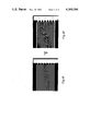
- FIG. 1A is an optical micrograph of an interdigital pattern of spatial period p of 2.54 ⁇ m that had been RF sputter etched into chromium on a photomask;
- FIG. 1B is an optical micrograph of RF sputter etched chromium following exposure of photoresist over the chromium through the photomask of FIG. 1A at a mask-to-resist gap of about 8 ⁇ m, producing the second spatial-frequency multiple (1.27 ⁇ m) of the pattern of FIG. 1A;
- FIG. 2 is a diagrammatic representation of spatial-period-division
- FIGS. 3A-3G are diagrammatic representations of the steps involved in fabricating a parent X-ray mask
- FIG. 4 is a cross-sectional diagram of an exemplary parent X-ray mask having a 196.8 nm period for exposing the second spatial-frequency-multiple, a 98.4 nm period grating;
- FIG. 5 is a cross-sectional diagram of an assembly with the means for maintaining a well-defined spacing between parent mask and substrate film during exposure;
- FIGS. 6A-6C show graphical representations of numerical calculations of the intensity of the second, third and fourth spatial-frequency multiples of the 196.8 nm period mask depicted in FIG. 6D assuming the cross sectional profile shown in FIG. 4, an X-ray source of 1 mm diameter and a source-to-mask distance of 115 mm;
- FIG. 7A is a photomicrograph of a parent mask having a 16.9 ⁇ m period
- FIGS. 7B-7C are photomicrographs of patterns exposed in photographic film through the parent mask of 7A using an incandescent lamp through an orange filter at separations suitable for producing the fourth, third and second spatial-frequency-multiples, respectively, of the parent mask in FIG. 7A;
- FIG. 8 is an electron micrograph showing the exposure in PMMA of a 98.4 nm spatial period grating using the parent mask shown in FIG. 4 having a 196.8 nm period;
- FIG. 9 is a computer generated plot of the near field diffraction from a parent mask of period "p" and slit width p/10 when it is illuminated with radiation of about 20% bandwidth and small angular divergence. Spatial frequency doubling (p/2), tripling (p/3), quadrupling (p/4) and quintripling (p/5 ) are shown.
- FIGS. 1A and 1B there are shown photomicrographs illustrating the doubling of a grating of spatial period 2.54 ⁇ m of FIG. 1A by shadow printing it at a gap of about 8 ⁇ m, yielding a grating of 1.27 ⁇ m spatial period as shown in FIG. 1B.
- Both gratings have been RF sputter etched into chromium, using photoresist to mask against the etching in accordance with the common practice of microlithography.
- FIG. 2 there is shown a diagrammatic representation of the basic principles of spatial-period division embodied in the invention.
- a periodic array of slits a-d and a'-c' is illuminated with radiant energy of wavelength ⁇ from a distant point source. Radiation from slits a and a' will be in phase, and produce an intensity maximum at point ⁇ for all distances S. However, at a certain distance S 2 , the difference in length between paths a', ⁇ and a ⁇ will be one wavelength, and the path length from the remaining slits to ⁇ will differ from a ⁇ by integral multiples of the wavelength ⁇ . The result is an intensity maximum at ⁇ , and by symmetry, also at ⁇ '.
- the intensity patterns of the spatial-frequency multiples are a function of the widths of the slits in the parent mask. For monochromatic collimated radiation the three db width of the intensity peaks is approximately equal to the width of the slits.
- the intensity patterns of the spatial-frequency-multiples will be approximately sinusoidal superimposed on a low level background, as illustrated in FIG. 9. Such patterns are adequate for exposure of high contrast re ##EQU1##
- a simple laboratory source of carbon K soft X-rays illuminated a resist, specifically PMMA, through an X-ray parent mask having a grating pattern of 196.8 nm spatial period with slits 40 nm wide, approximately the optimum slit-width for doubling.
- An oblique-shadowing technique such as described in copending application Ser. No. 43,309 of Dale C.
- the mask includes PMMA high-resolution X-ray-sensitive resist 11 on a first polyimide layer 12 with a gold plating base 13 sandwiched between layer 12 and a second polyimide layer 14 that is on a glass substrate 15.
- the PMMA is then X-ray exposed and developed to form slits 16 exposing the surface of the first polyimide layer 12 as shown in FIG. 3B.
- Chrome is then evaporated on the surface to form the chrome layer 17 as shown in FIG. 3C.
- the PMMA is then dissolved so that only the chrome strips 17 that were in the gaps 16 remain on the first polyimide surface 12 as shown in FIG. 3D.
- the first polyimide layer 12 is then oxygen ion beam-etched away except beneath the chrome strips 17 to expose the surface of the gold plating base 13 as shown in 3E.
- the exposed gold plating base 13 is electroplated with a gold layer 21 as shown in FIG. 3F.
- glass layer 15 is removed to complete the mask as shown in FIG. 3G with the bars formed by polyimide layer 12 and chrome 17 defining the slit widths and the separation between centers of these slits being the parent mask spatial period.
- FIG. 4 there is shown a cross section of a completed parent mask drawn substantially to scale with specific dimensions as set forth corresponding essentially to the structure of FIG. 3G but covered with an aluminum film 22.
- the gap S 2 between the grating of the parent mask at plating base 13 and the resist film should be approximately 4.3 ⁇ m.
- FIG. 5 there is shown in cross section an assembly including means for establishing and controlling this gap for exposing a PMMA resist 31 over a silicon oxide layer 32 on a silicon substrate 33 through parent mask 30 supported by spacer 34.
- Spacer 34 comprises solid members typically polyimide 35 between aluminum films 37. These solid portions attenuate the carbon K X-rays by about 9 db so that the image on photoresist 31 beneath them is underexposed.
- Penumbra due to the finite size of the source of carbon K X-rays 38, determine how close the assembly of FIG. 5 could be brought to the X-ray source, and thus determine exposure time.
- D the source-to-mask distance
- S the mask-to-substrate gap
- d the source diameter.
- S 4.3 ⁇ m
- ⁇ should be less than 196.8 nm/4.
- the source diameter was 1 mm, and thus D should be greater than 87 mm and was 115 mm, corresponding to an exposure time of 21 hours for the carbon K source operated at 4.8 kV and 70 ma.
- a synchrotron source of X-rays is preferred to allow shorter exposure times.
- Table 1 lists exposure times for a variety of spatial-frequency multiples and two parent mask periods for a synchrotron source. Alternatively, exposure times may be reduced by using a source of smaller diameter or linear geometry, or hot plasma sources.
- FIGS. 6A-6C there is shown a graphical representation of the calculated intensity for second, third and fourth spatial-frequency multiples, respectively, of the 196.8 nm. grating shown in FIG. 6D.
- the plots were calculated numerically, taking into account the angular divergence of the X-rays from the source.
- FIGS. 7A-7D there are shown photomicrographs of the parent mask, 7A, and of spatial frequency quadrupling, tripling and doubling, FIGS. 7B, C and D, respectively, produced in photographic film. Exposure was done through the parent mask with an incandescent lamp through an orange filter.
- FIG. 8 there is shown an electron micrograph of the pattern developed in the PMMA layer 31 of FIG. 5.
- a 98.4 nm spatial-period grating was produced by spatial-period division, that is the second spatial-frequency multiple of the 196.8 nm X-ray parent mask 30.
- the parent mask 30 producing the result in FIG. 8 was not the ideal structure of FIG. 4; gold having over-plated the slots in the polyimide layer 12 and bridged across.
- the invention can be extended down to the limit of microlithography, believed to be about 10 nm spatial period.
- the absorbing regions of the parent mask should have a high attenuation, preferably greater than 20 db. Otherwise, the radiation transmitted through the absorber can interfere with the diffracted radiation to produce undesirable spatial-harmonic components. Alternatively, if 50% of the incident radiation is phase shifted by ⁇ in passing through the mask pattern, the zero-order diffracted beam can be canceled as explained in (15). If p ⁇ 2 ⁇ , only the first-order diffracted beams will be present, and their interference will produce only the second spatial-frequency multiple. At optical and UV wavelengths, it is easy to achieve both zero-order cancellation and p ⁇ 2 ⁇ . At 4.5 nm wavelength, on the other hand, gold attenuates 128 db/ ⁇ m, and the phase shift is approximately 1° per nm. Both high attenuation and a ⁇ phase shift require a thick absorber of the order of 200 nm. This is possible using electroplating as illustrated in FIGS. 3 and 4.
- the parent mask introduces a phase shift of ⁇ , thereby cancelling the zero-order beam and p ⁇ 2 ⁇ , doubling of any spatial frequency occurs at all distances.
- This feature enables doubling of quasi-periodic structures such as variable period gratings, grids and Fresnel zone plates that may be useful in making structures of X-ray imaging and spectroscopy.
- particles such as electrons, ions and neutrons can also be used for spatial-period-division, by virtue of their wave nature.
Abstract
Soft carbon-K X-rays (38) expose a PMMA photoresist (31) on an oxide layer (32) of a silicon substrate (33) through a parent mask (30) separated a distance S from the resist by a spacer (34) with the parent mask slits (12, 17) defining a spatial period p to establish an intensity pattern of period p/n at the photomask with S=p2 /nλ, where λ is the wavelength of the incident radiation and λ<p.
Description
The Government has rights in this invention pursuant to Contract Number AF19(628)-78-C-0002 awarded by the U.S. Department of the Air Force.
This application is a continuation-in-part of Application Ser. No. 43,310 filed May 29, 1979, now abandoned.
The present invention relates in general to exposing patterns with radiant energy passing through masks and more particularly concerns novel apparatus and techniques for exposing patterns of spatial period p/n using near-field diffraction from masks of spatial period p with n being an integer greater than 1. The invention may be used with visible, UV or X-ray radiation (as well as electrons or ions) to produce gratings of exceptionally fine spatial period. A list of numbered references is appended.
Periodic and quasi-periodic structures of submicrometer spatial period are of fundamental importance in a number of areas such as guided wave optics as described in (1), distributive-feedback and distributed-Bragg-reflector lasers as described in (2), graphoepitaxy as described in (3) and (4) and planar superlattice electronic devices as described in (5). In addition high-quality periodic structures are essential elements in optics and spectroscopy at all wavelengths, and serve as calibration standards for scanning electron beam systems as described in (6). For spatial periods from about 2 μm to of the order of 0.2 μm, holographic lithography has been the preferred method of exposing periodic and quasi-periodic patterns, either directly on substrates of interest or on masks which are subsequently replicated photolithographically or with soft X-rays as described in (8). Holography in high-refractive-index media has been used to expose gratings of 110 nm period as described in (9), but the technique is cumbersome and difficult to extend for periods much below about 70 nm. Sources with wavelengths shorter than the He:Cd laser (325 nm) generally have limited coherence length and poor mode quality, or require complex apparatus for up-conversion as described in (10).
Accordingly, it is an important object of the invention to provide improved apparatus and techniques for exposing spatial periods, typically below 10 μm, useful in one or more of the applications described above and also in very-far UV and X-ray optics.
It is another object of the invention to achieve the preceding object with apparatus and techniques that are relatively free from complexity.
It is a further object of the invention to achieve one or more of the preceding objects, especially in conjunction with soft X-ray lithography.
It is an object of the invention to employ near-field diffraction from periodic and quasi-periodic "parent" masks to produce intensity patterns with spatial periods finer than the parent mask, a phenomenon previously observed with visible light and described in (11).
According to the invention, a source of radiant energy of wavelength λ illuminates a surface to be exposed through a mask having a spatial period p separated from the surface by a distance approximately Sn =p2 /nλ, where n is an integer greater than 1.
Numerous other features, objects and advantages of the invention will become apparent from the following specification when read in connection with the accompanying drawing in which:
FIG. 1A is an optical micrograph of an interdigital pattern of spatial period p of 2.54 μm that had been RF sputter etched into chromium on a photomask;
FIG. 1B is an optical micrograph of RF sputter etched chromium following exposure of photoresist over the chromium through the photomask of FIG. 1A at a mask-to-resist gap of about 8 μm, producing the second spatial-frequency multiple (1.27 μm) of the pattern of FIG. 1A;
FIG. 2 is a diagrammatic representation of spatial-period-division;
FIGS. 3A-3G are diagrammatic representations of the steps involved in fabricating a parent X-ray mask;
FIG. 4 is a cross-sectional diagram of an exemplary parent X-ray mask having a 196.8 nm period for exposing the second spatial-frequency-multiple, a 98.4 nm period grating;
FIG. 5 is a cross-sectional diagram of an assembly with the means for maintaining a well-defined spacing between parent mask and substrate film during exposure;
FIGS. 6A-6C show graphical representations of numerical calculations of the intensity of the second, third and fourth spatial-frequency multiples of the 196.8 nm period mask depicted in FIG. 6D assuming the cross sectional profile shown in FIG. 4, an X-ray source of 1 mm diameter and a source-to-mask distance of 115 mm;
FIG. 7A is a photomicrograph of a parent mask having a 16.9 μm period, and
FIGS. 7B-7C are photomicrographs of patterns exposed in photographic film through the parent mask of 7A using an incandescent lamp through an orange filter at separations suitable for producing the fourth, third and second spatial-frequency-multiples, respectively, of the parent mask in FIG. 7A;
FIG. 8 is an electron micrograph showing the exposure in PMMA of a 98.4 nm spatial period grating using the parent mask shown in FIG. 4 having a 196.8 nm period; and
FIG. 9 is a computer generated plot of the near field diffraction from a parent mask of period "p" and slit width p/10 when it is illuminated with radiation of about 20% bandwidth and small angular divergence. Spatial frequency doubling (p/2), tripling (p/3), quadrupling (p/4) and quintripling (p/5 ) are shown.
With reference now to the figures and drawings and more particularly FIGS. 1A and 1B above, there are shown photomicrographs illustrating the doubling of a grating of spatial period 2.54 μm of FIG. 1A by shadow printing it at a gap of about 8 μm, yielding a grating of 1.27 μm spatial period as shown in FIG. 1B. Both gratings have been RF sputter etched into chromium, using photoresist to mask against the etching in accordance with the common practice of microlithography.
Referring to FIG. 2, there is shown a diagrammatic representation of the basic principles of spatial-period division embodied in the invention. A periodic array of slits a-d and a'-c' is illuminated with radiant energy of wavelength λ from a distant point source. Radiation from slits a and a' will be in phase, and produce an intensity maximum at point α for all distances S. However, at a certain distance S2, the difference in length between paths a', β and aβ will be one wavelength, and the path length from the remaining slits to β will differ from aβ by integral multiples of the wavelength λ. The result is an intensity maximum at β, and by symmetry, also at β'. This intensity pattern with maxima at β', α and β, will have a spatial period p/2 and thus corresponds to a "doubling" of the original grating's spatial frequency. It can be shown that other spatial frequency multiples will occur at distances given by Sn =p2 /nλ, where n is an integer greater than 1. The intensity patterns of the spatial-frequency multiples are a function of the widths of the slits in the parent mask. For monochromatic collimated radiation the three db width of the intensity peaks is approximately equal to the width of the slits. If the source has some angular divergence and a moderate bandwidth of the order of 20%, the intensity patterns of the spatial-frequency-multiples will be approximately sinusoidal superimposed on a low level background, as illustrated in FIG. 9. Such patterns are adequate for exposure of high contrast re ##EQU1##
Theory predicts that the quality of the nth spatial-frequency-multiple is optimized; that is, spatial-harmonics less than n are minimized, if the slit width is ≦p/2n.
According to the specific example of the invention, a simple laboratory source of carbon K soft X-rays (λ=4.5 nm) illuminated a resist, specifically PMMA, through an X-ray parent mask having a grating pattern of 196.8 nm spatial period with slits 40 nm wide, approximately the optimum slit-width for doubling. An oblique-shadowing technique, such as described in copending application Ser. No. 43,309 of Dale C. Flanders filed May 29, 1979, entitled X-ray Lithography at ˜100 A° Linewidths Using X-ray Masks Fabricated by Shadowing Techniques assigned to the assignee of this application and incorporated herein by reference, was used to produce a first mask having absorber stripes effectively 40 nm wide. This first mask was then "reversed in polarity" upon a second mask, using a lift-off process, to yield a mask with 40 nm wide opening in gold 40 nm thick. The second mask was then used to produce a third mask using the process of FIG. 3A-3G which shows, in section, a fragmentary portion of the mask as it is processed. The mask includes PMMA high-resolution X-ray-sensitive resist 11 on a first polyimide layer 12 with a gold plating base 13 sandwiched between layer 12 and a second polyimide layer 14 that is on a glass substrate 15. The PMMA is then X-ray exposed and developed to form slits 16 exposing the surface of the first polyimide layer 12 as shown in FIG. 3B. Chrome is then evaporated on the surface to form the chrome layer 17 as shown in FIG. 3C. The PMMA is then dissolved so that only the chrome strips 17 that were in the gaps 16 remain on the first polyimide surface 12 as shown in FIG. 3D. The first polyimide layer 12 is then oxygen ion beam-etched away except beneath the chrome strips 17 to expose the surface of the gold plating base 13 as shown in 3E. The exposed gold plating base 13 is electroplated with a gold layer 21 as shown in FIG. 3F. Then glass layer 15 is removed to complete the mask as shown in FIG. 3G with the bars formed by polyimide layer 12 and chrome 17 defining the slit widths and the separation between centers of these slits being the parent mask spatial period. Referring to FIG. 4, there is shown a cross section of a completed parent mask drawn substantially to scale with specific dimensions as set forth corresponding essentially to the structure of FIG. 3G but covered with an aluminum film 22.
In order to expose a pattern with twice the spatial frequency of the parent mask of FIG. 4 (i.e., doubling), the gap S2 between the grating of the parent mask at plating base 13 and the resist film should be approximately 4.3 μm.
Referring to FIG. 5, there is shown in cross section an assembly including means for establishing and controlling this gap for exposing a PMMA resist 31 over a silicon oxide layer 32 on a silicon substrate 33 through parent mask 30 supported by spacer 34. Spacer 34 comprises solid members typically polyimide 35 between aluminum films 37. These solid portions attenuate the carbon K X-rays by about 9 db so that the image on photoresist 31 beneath them is underexposed.
Penumbra, due to the finite size of the source of carbon K X-rays 38, determine how close the assembly of FIG. 5 could be brought to the X-ray source, and thus determine exposure time. The penumbra is given by Δ=Sd/D, where D is the source-to-mask distance, S is the mask-to-substrate gap and d is the source diameter. For doubling a 196.8 nm. grating, S=4.3 μm, and Δ should be less than 196.8 nm/4. In the specific example the source diameter was 1 mm, and thus D should be greater than 87 mm and was 115 mm, corresponding to an exposure time of 21 hours for the carbon K source operated at 4.8 kV and 70 ma. A synchrotron source of X-rays is preferred to allow shorter exposure times. Table 1 lists exposure times for a variety of spatial-frequency multiples and two parent mask periods for a synchrotron source. Alternatively, exposure times may be reduced by using a source of smaller diameter or linear geometry, or hot plasma sources.
______________________________________
SPATIAL-PERIOD-DIVISION
USING SYNCHROTRON RADIATION
Power Radiated in 10% Bandwidth
Centered At 263 ev (λ = 4.7 nm)
                    APPROX      PERIOD EXPO-
                    DEPTH       PRO-   SURE*
       MUL-  GAP    OF FIELD    DUCED  TIME
       TIPLE (μm)
                    (μm)     (μm)
                                       (sec)
______________________________________
1.0 μm period
         2nd     98.0   32.7      0.5    2
parent mask
         3rd     65.4   12.2      0.33   3
(10nm slits)
         4th     49.0   6.5       0.25   4
         5th     39.2   4.1       0.20   5
0.2 μm period
         2nd     3.92   1.3       0.1    2
parent mask
         3rd     2.61   0.5       0.067  3
(10nm slits)
         4th     1.96   0.26      0.05   4
         5th     1.57   0.16      0.04   5
______________________________________
 *Calculated exposure times for PMMA and a source intensity of 1
 watt/cm.sup.2.
Referring to FIGS. 6A-6C, there is shown a graphical representation of the calculated intensity for second, third and fourth spatial-frequency multiples, respectively, of the 196.8 nm. grating shown in FIG. 6D. The plots were calculated numerically, taking into account the angular divergence of the X-rays from the source.
These plots were verified experimentally by a light optical simultaion of the X-ray configuration. A scale factor of approximately 100 was achieved by substituting white light through an orange filter for the 4.5 nm X-ray source and a parent photomask having a 16.9 μm period grating etched in chromium instead of the 196.8 nm. period grating X-ray mask 30. This chromium mask was exposed by electron beam lithography and had slit widths of 1.7 μm.
Referring to FIGS. 7A-7D, there are shown photomicrographs of the parent mask, 7A, and of spatial frequency quadrupling, tripling and doubling, FIGS. 7B, C and D, respectively, produced in photographic film. Exposure was done through the parent mask with an incandescent lamp through an orange filter.
Referring to FIG. 8, there is shown an electron micrograph of the pattern developed in the PMMA layer 31 of FIG. 5. A 98.4 nm spatial-period grating was produced by spatial-period division, that is the second spatial-frequency multiple of the 196.8 nm X-ray parent mask 30. The parent mask 30 producing the result in FIG. 8 was not the ideal structure of FIG. 4; gold having over-plated the slots in the polyimide layer 12 and bridged across.
In principle, the invention can be extended down to the limit of microlithography, believed to be about 10 nm spatial period.
The absorbing regions of the parent mask should have a high attenuation, preferably greater than 20 db. Otherwise, the radiation transmitted through the absorber can interfere with the diffracted radiation to produce undesirable spatial-harmonic components. Alternatively, if 50% of the incident radiation is phase shifted by π in passing through the mask pattern, the zero-order diffracted beam can be canceled as explained in (15). If p<2λ, only the first-order diffracted beams will be present, and their interference will produce only the second spatial-frequency multiple. At optical and UV wavelengths, it is easy to achieve both zero-order cancellation and p<2λ. At 4.5 nm wavelength, on the other hand, gold attenuates 128 db/μm, and the phase shift is approximately 1° per nm. Both high attenuation and a π phase shift require a thick absorber of the order of 200 nm. This is possible using electroplating as illustrated in FIGS. 3 and 4.
If the parent mask introduces a phase shift of π, thereby cancelling the zero-order beam and p<2λ, doubling of any spatial frequency occurs at all distances. This feature enables doubling of quasi-periodic structures such as variable period gratings, grids and Fresnel zone plates that may be useful in making structures of X-ray imaging and spectroscopy.
In addition to optical, UV and X-ray photons, particles such as electrons, ions and neutrons can also be used for spatial-period-division, by virtue of their wave nature.
Spatial-period-division applies to grids and arrays of apertures. Such an application would be an elementary extension of the methods taught above.
There has been described novel apparatus and techniques relatively free from complexity that provide a means of exposing large-area, low-distortion, periodic structures. Spatial periods below 100 nm are readily exposed. When used with soft X-rays, back reflection from substrates is avoided, thereby permitting high aspect-ratio structures. The profile of the intensity pattern can be altered by varying the parent-mask slit width.
It is evident that those skilled in the art may now make numerous uses and modifications of and departures from the specific embodiments described herein without departing from the inventive concepts. Consequently, the invention is to be construed as embracing each and every novel feature and novel combination of features present in or possessed by the apparatus and techniques herein disclosed and limited solely by the spirit and scope of the appended claims.
1. A. Yariv, Sci. Amer., 240, 64-72 (1979).
2. A. Yariv and M. Nakamura, IEEE J. Quantum Electronics QE-13, 233-253 (1977).
3. H. I. Smith and D. C. Flanders, Appl. Phys. Lett. 32, 349-350 (1978).
4. M. W. Geis, D. C. Flanders and H. I. Smith, Appl. Phys, Lett. 35, 71 (1979).
5. H. Sakaki, K. Wagatsuma, J. Hamasaki and S. Saito, Thin Solid Films 36, 497 (1976).
6. H. I. Smith, S. R. Chinn and P. D. DeGraff, J. Vac. Sci. Tech. 12, 1262-1265 (1975).
7. D. C. Shaver, D. C. Flanders, H. I. Smith and N. M. Ceglio, J. Vac. Sci. Tech. 16, 1926 (1979).
8. D. C. Flanders, H. I. Smith, H. W. Lehmann, R. Widmer and D. C. Shaver, Appl. Phy. Lett. 32, 112-114 (1978).
9. C. V. Shank and R. V. Schmidt, Appl. Phys. Lett. 23, 154-155 (1973).
10. G. C. Bjorklund, S. E. Harris, and J. F. Young, Appl. Phys. Lett. 25, 451-452 (1974).
11. T. Winthrop and C. R. Worthington, J. Opt. Soc. Amer. 55, 373-381 (1965).
12. D. C. Flanders, J. Vac. Sci. Tech. 16, 1615 (1979).
13. K. Knop, Optics Comm. 18, 298-303 (1976).
14. P. D. DeGraff, D. C. Flanders, J. Vac. Sci. Tech. 16, 1906 (1979).
Claims (8)
1. A method for producing gratings which method includes the steps of,
exposing a substrate to X-ray radiant energy of wavelength λ through a parent mask having a pattern of slits of period p defined by X-ray absorbing material with sufficient attenuation to produce with the X-ray energy transmitted through said parent mask a sharp image on said substrate,
and spacing said parent mask from said substrate a distance S substantially equal to p2 /nλ where λ is the wavelength of said X-radiation and n is an integer greater than one to provide said image with an intensity pattern of period p/n on said substrate.
2. Apparatus for practicing the process of claim 1 comprising,
said substrate carrying an X-ray radiation sensitive layer on the surface thereof,
said parent mask,
and means for supporting said parent mask spaced from said layer said distance S.
3. Apparatus in accordance with claim 2 wherein said resist layer is PMMA.
4. Apparatus in accordance with claim 2 wherein the width of each of said slits is ≦p/2n.
5. A method for producing gratings, in accordance with claim 1 wherein the spatial period of the pattern of slits on the parent mask varies as a function of position to produce quasi-periodic gratings.
6. A method for producing grids which method includes the steps of exposing a substrate to X-ray radiant energy of wavelength λ through a parent mask having a grid pattern of apertures, the widths of which are less than one half of the local spatial period p defined by X-ray absorbing material with sufficient attenuation to produce with the X-ray energy transmitted through said parent mask a sharp image on said substrate, and spacing said parent mask from said substrate a distance S substantially equal to p2 /nλ where λ is the wavelength of said X-radiation and n is an integer greater than one, to provide said image with an intensity pattern of period p/n on said substrate.
7. A method of producing a Fresnel zone pattern which method includes the steps of exposing a substrate to radiant energy of wavelength λ through a parent mask having a pattern of Fresnel-zone concentric circular apertures, the widths of which are less than one half of the local spatial period, p, and spacing said parent mask from said substrate a distance S substantially equal to p2 /nλ where λ is the wavelength of said radiation and n is an integer greater than one, to provide an intensity pattern on said substrate having the form of a Fresnel zone pattern.
8. A method for producing gratings, grids and Fresnel-zone patterns which method includes the steps of exposing a substrate to radiant energy of wavelength λ through a parent mask having a pattern of apertures in the form of a grating, a grid or a set of Fresnel zones, wherein the thickness of the material between the parent mask apertures is such that radiation passing through it suffers a differential phase shift that is an odd multiple of π radians relative to radiation passing through the apertures.
Priority Applications (3)
| Application Number | Priority Date | Filing Date | Title |
|---|---|---|---|
| US06/140,150 US4360586A (en) | 1979-05-29 | 1980-04-14 | Spatial period division exposing |
| DE8080301759T DE3069266D1 (en) | 1979-05-29 | 1980-05-28 | Method of and apparatus for producing a diffracting means |
| EP80301759A EP0020132B1 (en) | 1979-05-29 | 1980-05-28 | Method of and apparatus for producing a diffracting means |
Applications Claiming Priority (2)
| Application Number | Priority Date | Filing Date | Title |
|---|---|---|---|
| US4331079A | 1979-05-29 | 1979-05-29 | |
| US06/140,150 US4360586A (en) | 1979-05-29 | 1980-04-14 | Spatial period division exposing |
Related Parent Applications (1)
| Application Number | Title | Priority Date | Filing Date |
|---|---|---|---|
| US4331079A Continuation-In-Part | 1979-05-29 | 1979-05-29 |
Publications (1)
| Publication Number | Publication Date |
|---|---|
| US4360586A true US4360586A (en) | 1982-11-23 |
Family
ID=26720269
Family Applications (1)
| Application Number | Title | Priority Date | Filing Date |
|---|---|---|---|
| US06/140,150 Expired - Lifetime US4360586A (en) | 1979-05-29 | 1980-04-14 | Spatial period division exposing |
Country Status (3)
| Country | Link |
|---|---|
| US (1) | US4360586A (en) |
| EP (1) | EP0020132B1 (en) |
| DE (1) | DE3069266D1 (en) |
Cited By (52)
| Publication number | Priority date | Publication date | Assignee | Title |
|---|---|---|---|---|
| US4806442A (en) * | 1985-03-20 | 1989-02-21 | Fujitsu Limited | Spatial phase modulating masks and production processes thereof, and processes for the formation of phase-shifted diffraction gratings |
| US4846552A (en) * | 1986-04-16 | 1989-07-11 | The United States Of America As Represented By The Secretary Of The Air Force | Method of fabricating high efficiency binary planar optical elements |
| US4890309A (en) * | 1987-02-25 | 1989-12-26 | Massachusetts Institute Of Technology | Lithography mask with a π-phase shifting attenuator |
| EP0352975A2 (en) * | 1988-07-26 | 1990-01-31 | AT&T Corp. | Resolution doubling lithography technique |
| US5020879A (en) * | 1987-06-27 | 1991-06-04 | Shimadzu Corporation | Flexible replica grating |
| US5187726A (en) * | 1991-09-30 | 1993-02-16 | Wisconsin Alumni Research Foundation | High resolution X-ray lithography using phase shift masks |
| US5194344A (en) * | 1991-03-26 | 1993-03-16 | Micron Technology, Inc. | Method of fabricating phase shift reticles including chemically mechanically planarizing |
| US5194345A (en) * | 1991-05-14 | 1993-03-16 | Micron Technology, Inc. | Method of fabricating phase shift reticles |
| US5194346A (en) * | 1991-04-15 | 1993-03-16 | Micron Technology, Inc. | Method of fabricating phase shifting reticles with an accurate phase shift layer |
| WO1993009546A1 (en) * | 1991-11-01 | 1993-05-13 | Howells Malcolm R | X-ray lithography using holographic images |
| US5217830A (en) * | 1991-03-26 | 1993-06-08 | Micron Technology, Inc. | Method of fabricating phase shifting reticles using ion implantation |
| US5240796A (en) * | 1991-07-09 | 1993-08-31 | Micron Technology, Inc. | Method of fabricating a chromeless phase shift reticle |
| US5260558A (en) * | 1992-05-20 | 1993-11-09 | Massachusetts Institute Of Technology | Measurements using balanced illumination optical microscopy |
| US5272024A (en) * | 1992-04-08 | 1993-12-21 | International Business Machines Corporation | Mask-structure and process to repair missing or unwanted phase-shifting elements |
| US5288569A (en) * | 1992-04-23 | 1994-02-22 | International Business Machines Corporation | Feature biassing and absorptive phase-shifting techniques to improve optical projection imaging |
| US5340637A (en) * | 1986-09-16 | 1994-08-23 | Hitachi, Ltd. | Optical device diffraction gratings and a photomask for use in the same |
| US5342713A (en) * | 1990-06-21 | 1994-08-30 | Oki Electric Industry Co., Ltd. | Phase shifting mask |
| US5352550A (en) * | 1988-11-22 | 1994-10-04 | Hitachi, Ltd. | Mask for manufacturing semiconductor devices and method of manufacture thereof |
| US5362584A (en) * | 1993-04-02 | 1994-11-08 | International Business Machines Corporation | Phase-shifting transparent lithographic mask for writing contiguous structures from noncontiguous mask areas |
| US5384219A (en) * | 1992-08-21 | 1995-01-24 | Intel Corporation | Reticle with structurally identical inverted phase-shifted features |
| US5411824A (en) * | 1993-01-21 | 1995-05-02 | Sematech, Inc. | Phase shifting mask structure with absorbing/attenuating sidewalls for improved imaging |
| US5418095A (en) * | 1993-01-21 | 1995-05-23 | Sematech, Inc. | Method of fabricating phase shifters with absorbing/attenuating sidewalls using an additive process |
| US5420719A (en) * | 1993-09-15 | 1995-05-30 | Lumonics Inc. | Laser beam frequency doubling system |
| US5429896A (en) * | 1992-12-07 | 1995-07-04 | Hitachi, Ltd. | Photomask and pattern forming method employing the same |
| US5437947A (en) * | 1994-03-04 | 1995-08-01 | Goldstar Electron Co., Ltd. | Phase shifting mask and method of manufacturing the same |
| US5446521A (en) * | 1993-06-30 | 1995-08-29 | Intel Corporation | Phase-shifted opaquing ring |
| US5472811A (en) * | 1993-01-21 | 1995-12-05 | Sematech, Inc. | Phase shifting mask structure with multilayer optical coating for improved transmission |
| USRE35315E (en) * | 1989-10-02 | 1996-08-20 | Okamoto; Yoshihiko | Mask for manufacturing semiconductor device and method of manufacture thereof |
| US5595843A (en) * | 1995-03-30 | 1997-01-21 | Intel Corporation | Layout methodology, mask set, and patterning method for phase-shifting lithography |
| US5597666A (en) * | 1991-01-14 | 1997-01-28 | Gold Star Electron Co., Ltd. | Method for fabrication of a mask |
| US5700601A (en) * | 1994-06-29 | 1997-12-23 | Hitachi, Ltd. | Photomask, manufacture of photomask, formation of pattern, manufacture of semiconductor device, and mask pattern design system |
| US5700602A (en) * | 1992-08-21 | 1997-12-23 | Intel Corporation | Method and apparatus for precision determination of phase-shift in a phase-shifted reticle |
| US5733687A (en) * | 1994-09-29 | 1998-03-31 | Kabushiki Kaisha Toshiba | Photomask, exposing method using photomask, and manufacturing method of photomask |
| US5786931A (en) * | 1995-04-13 | 1998-07-28 | Johannes Heidenhain Gmbh | Phase grating and method of producing phase grating |
| US6671235B1 (en) | 2000-03-27 | 2003-12-30 | Ultratech Stepper, Inc. | Method of and apparatus for defining disk tracks in magnetic recording media |
| EP1447714A2 (en) * | 2003-02-14 | 2004-08-18 | Paul Scherrer Institut | Method for generating a circular periodic structure on a basic support material |
| WO2004072737A3 (en) * | 2003-02-14 | 2005-03-03 | Scherrer Inst Paul | Method for generating a circular periodic structure on a basic support material |
| US20080145765A1 (en) * | 2004-02-12 | 2008-06-19 | Optaglio Ltd. | Metal Identification Platelet and Method of Producing Thereof |
| US20080186579A1 (en) * | 2004-10-22 | 2008-08-07 | Paul Scherrer Institut | System and a Method for Generating Periodic and/or Quasi-Periodic Pattern on a Sample |
| US20110199598A1 (en) * | 2010-02-16 | 2011-08-18 | Solak Harun H | Lithographic fabrication of general periodic structures |
| WO2012004745A1 (en) | 2010-07-07 | 2012-01-12 | Eulitha A.G. | A method and apparatus for printing a periodic pattern with large depth of focus |
| WO2012049638A1 (en) | 2010-10-13 | 2012-04-19 | Eulitha A.G. | Method and apparatus for printing periodic patterns |
| WO2012066489A2 (en) | 2010-11-16 | 2012-05-24 | Eulitha A.G. | Method and apparatus for printing high-resolution two-dimensional periodic patterns |
| WO2012095795A2 (en) | 2011-01-12 | 2012-07-19 | Eulitha A.G. | Method and system for printing high-resolution periodic patterns |
| WO2012164539A1 (en) | 2011-06-01 | 2012-12-06 | Eulitha A.G. | Printing periodic patterns using multiple lasers |
| CN103245991A (en) * | 2013-04-02 | 2013-08-14 | 厦门大学 | Method for doubling grating space frequency |
| WO2014147562A2 (en) | 2013-03-18 | 2014-09-25 | Eulitha A.G. | Methods and systems for printing periodic patterns |
| US20150022892A1 (en) * | 2012-03-08 | 2015-01-22 | Max-Planck-Gesellschaft Zur Foerderung Der Wissenschaften E.V. | Method of Producing a Fresnel Zone Plate for Applications in High Energy Radiation |
| US9007566B2 (en) | 2010-07-07 | 2015-04-14 | Eulitha Ag | Apparatus and method for printing a periodic pattern with a large depth of focus |
| US9036133B2 (en) | 2010-02-16 | 2015-05-19 | Eulitha Ag | Lithographic fabrication of general periodic structures by exposing a photosensitive layer to a range of lateral intensity distributions |
| WO2017103817A1 (en) | 2015-12-14 | 2017-06-22 | Eulitha A.G. | Methods and systems for printing arrays of features |
| US11042098B2 (en) * | 2019-02-15 | 2021-06-22 | Applied Materials, Inc. | Large area high resolution feature reduction lithography technique |
Families Citing this family (7)
| Publication number | Priority date | Publication date | Assignee | Title |
|---|---|---|---|---|
| US4405238A (en) * | 1981-05-20 | 1983-09-20 | Ibm Corporation | Alignment method and apparatus for x-ray or optical lithography |
| US4530736A (en) * | 1983-11-03 | 1985-07-23 | International Business Machines Corporation | Method for manufacturing Fresnel phase reversal plate lenses |
| DE3611246A1 (en) * | 1986-04-04 | 1987-10-15 | Kernforschungsz Karlsruhe | METHOD FOR PRODUCING A PASSIVE OPTICAL COMPONENT WITH ONE OR MORE ECHELETTE GRIDS, AND COMPONENT PRODUCED BY THIS METHOD |
| JP3311302B2 (en) * | 1998-10-27 | 2002-08-05 | キヤノン株式会社 | Exposure method |
| JP3387834B2 (en) * | 1998-10-29 | 2003-03-17 | キヤノン株式会社 | X-ray exposure method and device manufacturing method |
| DE10025694C2 (en) * | 2000-05-24 | 2003-06-05 | Zeiss Carl | Use of a diffraction grating |
| CN105259739B (en) * | 2015-11-12 | 2017-06-30 | 中国科学院光电技术研究所 | The photolithography method and device of periodic array in two dimensions are prepared from imaging based on ultraviolet wide spectrum |
Citations (2)
| Publication number | Priority date | Publication date | Assignee | Title |
|---|---|---|---|---|
| DE1285763B (en) * | 1967-11-08 | 1968-12-19 | Wenczler & Heidenhain | Process for making optical diffraction gratings |
| US3615449A (en) * | 1969-09-25 | 1971-10-26 | Rca Corp | Method of generating high area-density periodic arrays by diffraction imaging |
Family Cites Families (4)
| Publication number | Priority date | Publication date | Assignee | Title |
|---|---|---|---|---|
| US3728117A (en) * | 1968-01-20 | 1973-04-17 | Heidenhain J Fa | Optical diffraction grid |
| US3640197A (en) * | 1970-01-22 | 1972-02-08 | Motorola Inc | Production of fine single lines and of discrete closely spaced fine lines |
| DE2116713B2 (en) * | 1971-04-06 | 1974-03-28 | Ibm Deutschland Gmbh, 7000 Stuttgart | Exposure method for imaging very finely structured light patterns on photoresist layers and a suitable exposure device |
| US3761264A (en) * | 1971-10-12 | 1973-09-25 | Rca Corp | Method of defining a detailed pattern on a surface of a body |
-
1980
- 1980-04-14 US US06/140,150 patent/US4360586A/en not_active Expired - Lifetime
- 1980-05-28 EP EP80301759A patent/EP0020132B1/en not_active Expired
- 1980-05-28 DE DE8080301759T patent/DE3069266D1/en not_active Expired
Patent Citations (2)
| Publication number | Priority date | Publication date | Assignee | Title |
|---|---|---|---|---|
| DE1285763B (en) * | 1967-11-08 | 1968-12-19 | Wenczler & Heidenhain | Process for making optical diffraction gratings |
| US3615449A (en) * | 1969-09-25 | 1971-10-26 | Rca Corp | Method of generating high area-density periodic arrays by diffraction imaging |
Non-Patent Citations (4)
| Title |
|---|
| Edgar "Optica Acta" vol. 16, No. 3, pp. 281-287 1969. * |
| Knop "Optics Comm." vol. 18, pp. 298-303 1976. * |
| Kodate et al., "Applied Optics" vol. 14, No. 2, pp. 522-525 Feb. 1975. * |
| Rogers, "Jour. Opt. Soc. America" vol. 62, No. 7, pp. 917, 918, Ju. 1972. * |
Cited By (98)
| Publication number | Priority date | Publication date | Assignee | Title |
|---|---|---|---|---|
| US4806442A (en) * | 1985-03-20 | 1989-02-21 | Fujitsu Limited | Spatial phase modulating masks and production processes thereof, and processes for the formation of phase-shifted diffraction gratings |
| US4846552A (en) * | 1986-04-16 | 1989-07-11 | The United States Of America As Represented By The Secretary Of The Air Force | Method of fabricating high efficiency binary planar optical elements |
| US5340637A (en) * | 1986-09-16 | 1994-08-23 | Hitachi, Ltd. | Optical device diffraction gratings and a photomask for use in the same |
| US4890309A (en) * | 1987-02-25 | 1989-12-26 | Massachusetts Institute Of Technology | Lithography mask with a π-phase shifting attenuator |
| US5020879A (en) * | 1987-06-27 | 1991-06-04 | Shimadzu Corporation | Flexible replica grating |
| EP0352975A2 (en) * | 1988-07-26 | 1990-01-31 | AT&T Corp. | Resolution doubling lithography technique |
| EP0352975A3 (en) * | 1988-07-26 | 1990-07-04 | AT&T Corp. | Resolution doubling lithography technique |
| US4947413A (en) * | 1988-07-26 | 1990-08-07 | At&T Bell Laboratories | Resolution doubling lithography technique |
| US6420075B1 (en) | 1988-11-22 | 2002-07-16 | Hitachi, Ltd. | Mask for manufacturing semiconductor device and method of manufacture thereof |
| US6733933B2 (en) | 1988-11-22 | 2004-05-11 | Renesas Technology Corporation | Mask for manufacturing semiconductor device and method of manufacture thereof |
| US20050164128A1 (en) * | 1988-11-22 | 2005-07-28 | Yoshihiko Okamoto | Mask for manufacturing semiconductor device and method of manufacture thereof |
| US5948574A (en) * | 1988-11-22 | 1999-09-07 | Hitachi, Ltd. | Mask for manufacturing semiconductor device and method of manufacture thereof |
| US5484671A (en) * | 1988-11-22 | 1996-01-16 | Hitachi, Ltd. | Mask for manufacturing semiconductor device and method of manufacture thereof |
| US5830606A (en) * | 1988-11-22 | 1998-11-03 | Hitachi, Ltd. | Mask for manufacturing semiconductor device and method of manufacture thereof |
| US20040185381A1 (en) * | 1988-11-22 | 2004-09-23 | Yoshihiko Okamoto | Mask for manufacturing semiconductor device and method of manufacture thereof |
| US6458497B2 (en) | 1988-11-22 | 2002-10-01 | Hitachi, Ltd. | Mask for manufacturing semiconductor device and method of manufacture thereof |
| US6548213B2 (en) | 1988-11-22 | 2003-04-15 | Hitachi, Ltd. | Mask for manufacturing semiconductor device and method of manufacture thereof |
| US7008736B2 (en) | 1988-11-22 | 2006-03-07 | Renesas Technology Corp. | Semiconductor integrated circuit device fabrication method using a mask having a phase shifting film covering region and an opening region |
| US6106981A (en) * | 1988-11-22 | 2000-08-22 | Hitachi, Ltd. | Mask for manufacturing semiconductor device and method of manufacture thereof |
| US5352550A (en) * | 1988-11-22 | 1994-10-04 | Hitachi, Ltd. | Mask for manufacturing semiconductor devices and method of manufacture thereof |
| US5358807A (en) * | 1988-11-22 | 1994-10-25 | Hitachi, Ltd. | Mask for manufacturing semiconductor device and method of manufacture thereof |
| USRE35315E (en) * | 1989-10-02 | 1996-08-20 | Okamoto; Yoshihiko | Mask for manufacturing semiconductor device and method of manufacture thereof |
| US5342713A (en) * | 1990-06-21 | 1994-08-30 | Oki Electric Industry Co., Ltd. | Phase shifting mask |
| US5597666A (en) * | 1991-01-14 | 1997-01-28 | Gold Star Electron Co., Ltd. | Method for fabrication of a mask |
| US5194344A (en) * | 1991-03-26 | 1993-03-16 | Micron Technology, Inc. | Method of fabricating phase shift reticles including chemically mechanically planarizing |
| US5217830A (en) * | 1991-03-26 | 1993-06-08 | Micron Technology, Inc. | Method of fabricating phase shifting reticles using ion implantation |
| US5194346A (en) * | 1991-04-15 | 1993-03-16 | Micron Technology, Inc. | Method of fabricating phase shifting reticles with an accurate phase shift layer |
| US5194345A (en) * | 1991-05-14 | 1993-03-16 | Micron Technology, Inc. | Method of fabricating phase shift reticles |
| US5240796A (en) * | 1991-07-09 | 1993-08-31 | Micron Technology, Inc. | Method of fabricating a chromeless phase shift reticle |
| US5187726A (en) * | 1991-09-30 | 1993-02-16 | Wisconsin Alumni Research Foundation | High resolution X-ray lithography using phase shift masks |
| US5455850A (en) * | 1991-11-01 | 1995-10-03 | The Regents Of The Univerity Of Calif. | X-ray lithography using holographic images |
| WO1993009546A1 (en) * | 1991-11-01 | 1993-05-13 | Howells Malcolm R | X-ray lithography using holographic images |
| US5612986A (en) * | 1991-11-01 | 1997-03-18 | Lawrence Berkeley Laboratory, University Of Ca | X-ray lithography using holographic images |
| US5272024A (en) * | 1992-04-08 | 1993-12-21 | International Business Machines Corporation | Mask-structure and process to repair missing or unwanted phase-shifting elements |
| US5288569A (en) * | 1992-04-23 | 1994-02-22 | International Business Machines Corporation | Feature biassing and absorptive phase-shifting techniques to improve optical projection imaging |
| US5260558A (en) * | 1992-05-20 | 1993-11-09 | Massachusetts Institute Of Technology | Measurements using balanced illumination optical microscopy |
| US5700602A (en) * | 1992-08-21 | 1997-12-23 | Intel Corporation | Method and apparatus for precision determination of phase-shift in a phase-shifted reticle |
| US5384219A (en) * | 1992-08-21 | 1995-01-24 | Intel Corporation | Reticle with structurally identical inverted phase-shifted features |
| US5656400A (en) * | 1992-12-07 | 1997-08-12 | Hitachi, Ltd. | Photomask and pattern forming method employing the same |
| US20080057408A9 (en) * | 1992-12-07 | 2008-03-06 | Renesas Technology Corp. | Photomask and pattern forming method employing the same |
| US6733953B2 (en) | 1992-12-07 | 2004-05-11 | Renesas Technology Corp. | Photomask and pattern forming method employing the same |
| US20040161707A1 (en) * | 1992-12-07 | 2004-08-19 | Renesas Technology Corp. | Photomask and pattern forming method employing the same |
| US5578421A (en) * | 1992-12-07 | 1996-11-26 | Hitachi, Ltd. | Photomask and pattern forming method employing the same |
| US7115344B2 (en) | 1992-12-07 | 2006-10-03 | Renesas Technology Corp. | Photomask and pattern forming method employing the same |
| US6258513B1 (en) | 1992-12-07 | 2001-07-10 | Hitachi, Ltd. | Photomask and pattern forming method employing the same |
| US5851703A (en) * | 1992-12-07 | 1998-12-22 | Hitachi, Ltd. | Photomask and pattern forming method employing the same |
| US6383718B2 (en) | 1992-12-07 | 2002-05-07 | Hitachi, Ltd. | Photomask and pattern forming method employing the same |
| US5429896A (en) * | 1992-12-07 | 1995-07-04 | Hitachi, Ltd. | Photomask and pattern forming method employing the same |
| US6013398A (en) * | 1992-12-07 | 2000-01-11 | Hitachi, Ltd. | Photomask and pattern forming method employing the same |
| US6087074A (en) * | 1992-12-07 | 2000-07-11 | Hitachi, Ltd. | Photomask and pattern forming method employing the same |
| US20050158638A1 (en) * | 1992-12-07 | 2005-07-21 | Renesas Technology Corp. | Photomask and pattern forming method employing the same |
| US5418095A (en) * | 1993-01-21 | 1995-05-23 | Sematech, Inc. | Method of fabricating phase shifters with absorbing/attenuating sidewalls using an additive process |
| US5472811A (en) * | 1993-01-21 | 1995-12-05 | Sematech, Inc. | Phase shifting mask structure with multilayer optical coating for improved transmission |
| US5411824A (en) * | 1993-01-21 | 1995-05-02 | Sematech, Inc. | Phase shifting mask structure with absorbing/attenuating sidewalls for improved imaging |
| US5362584A (en) * | 1993-04-02 | 1994-11-08 | International Business Machines Corporation | Phase-shifting transparent lithographic mask for writing contiguous structures from noncontiguous mask areas |
| US5446521A (en) * | 1993-06-30 | 1995-08-29 | Intel Corporation | Phase-shifted opaquing ring |
| US5420719A (en) * | 1993-09-15 | 1995-05-30 | Lumonics Inc. | Laser beam frequency doubling system |
| US5437947A (en) * | 1994-03-04 | 1995-08-01 | Goldstar Electron Co., Ltd. | Phase shifting mask and method of manufacturing the same |
| US5700601A (en) * | 1994-06-29 | 1997-12-23 | Hitachi, Ltd. | Photomask, manufacture of photomask, formation of pattern, manufacture of semiconductor device, and mask pattern design system |
| US5895741A (en) * | 1994-06-29 | 1999-04-20 | Hitachi, Ltd. | Photomask, manufacture of photomask, formation of pattern, manufacture of semiconductor device, and mask pattern design system |
| US5733687A (en) * | 1994-09-29 | 1998-03-31 | Kabushiki Kaisha Toshiba | Photomask, exposing method using photomask, and manufacturing method of photomask |
| US5595843A (en) * | 1995-03-30 | 1997-01-21 | Intel Corporation | Layout methodology, mask set, and patterning method for phase-shifting lithography |
| US5620816A (en) * | 1995-03-30 | 1997-04-15 | Intel Corporation | Layout methodology, mask set, and patterning method for phase-shifting lithography |
| US5635316A (en) * | 1995-03-30 | 1997-06-03 | Intel Corporation | Layout methodology, mask set, and patterning method for phase-shifting lithography |
| US5786931A (en) * | 1995-04-13 | 1998-07-28 | Johannes Heidenhain Gmbh | Phase grating and method of producing phase grating |
| US6671235B1 (en) | 2000-03-27 | 2003-12-30 | Ultratech Stepper, Inc. | Method of and apparatus for defining disk tracks in magnetic recording media |
| EP1447714A3 (en) * | 2003-02-14 | 2005-02-16 | Paul Scherrer Institut | Method for generating a circular periodic structure on a basic support material |
| US20060098566A1 (en) * | 2003-02-14 | 2006-05-11 | Paul Scherrer Institut | Method for generating a circular periodic structure on a basic support material |
| WO2004072737A3 (en) * | 2003-02-14 | 2005-03-03 | Scherrer Inst Paul | Method for generating a circular periodic structure on a basic support material |
| EP1447714A2 (en) * | 2003-02-14 | 2004-08-18 | Paul Scherrer Institut | Method for generating a circular periodic structure on a basic support material |
| US7858268B2 (en) | 2003-02-14 | 2010-12-28 | Eulitha Ag | Method for generating a circular periodic structure on a basic support material |
| US8211595B2 (en) * | 2004-02-12 | 2012-07-03 | Optaglio, Ltd. | Metal identification platelet and method of producing thereof |
| US20080145765A1 (en) * | 2004-02-12 | 2008-06-19 | Optaglio Ltd. | Metal Identification Platelet and Method of Producing Thereof |
| US8841046B2 (en) * | 2004-10-22 | 2014-09-23 | Eulitha Ag | System and a method for generating periodic and/or quasi-periodic pattern on a sample |
| US20080186579A1 (en) * | 2004-10-22 | 2008-08-07 | Paul Scherrer Institut | System and a Method for Generating Periodic and/or Quasi-Periodic Pattern on a Sample |
| US8368871B2 (en) | 2010-02-16 | 2013-02-05 | Eulitha Ag | Lithographic fabrication of general periodic structures |
| US9036133B2 (en) | 2010-02-16 | 2015-05-19 | Eulitha Ag | Lithographic fabrication of general periodic structures by exposing a photosensitive layer to a range of lateral intensity distributions |
| US20110199598A1 (en) * | 2010-02-16 | 2011-08-18 | Solak Harun H | Lithographic fabrication of general periodic structures |
| WO2012004745A1 (en) | 2010-07-07 | 2012-01-12 | Eulitha A.G. | A method and apparatus for printing a periodic pattern with large depth of focus |
| US9007566B2 (en) | 2010-07-07 | 2015-04-14 | Eulitha Ag | Apparatus and method for printing a periodic pattern with a large depth of focus |
| US8524443B2 (en) | 2010-07-07 | 2013-09-03 | Eulitha A.G. | Method and apparatus for printing a periodic pattern with a large depth of focus |
| WO2012049638A1 (en) | 2010-10-13 | 2012-04-19 | Eulitha A.G. | Method and apparatus for printing periodic patterns |
| WO2012066489A3 (en) * | 2010-11-16 | 2012-07-12 | Eulitha A.G. | Method and apparatus for printing high-resolution two-dimensional periodic patterns |
| CN103370654B (en) * | 2010-11-16 | 2015-09-02 | 尤利塔股份公司 | For printing the method and apparatus of high resolution 2 d periodic patterns |
| CN103370654A (en) * | 2010-11-16 | 2013-10-23 | 尤利塔股份公司 | Method and apparatus for printing high-resolution two-dimensional periodic patterns |
| WO2012066489A2 (en) | 2010-11-16 | 2012-05-24 | Eulitha A.G. | Method and apparatus for printing high-resolution two-dimensional periodic patterns |
| US8904316B2 (en) | 2010-11-16 | 2014-12-02 | Eulitha A.G. | Method and apparatus for printing high-resolution two-dimensional periodic patterns |
| WO2012095795A2 (en) | 2011-01-12 | 2012-07-19 | Eulitha A.G. | Method and system for printing high-resolution periodic patterns |
| WO2012164539A1 (en) | 2011-06-01 | 2012-12-06 | Eulitha A.G. | Printing periodic patterns using multiple lasers |
| US20150022892A1 (en) * | 2012-03-08 | 2015-01-22 | Max-Planck-Gesellschaft Zur Foerderung Der Wissenschaften E.V. | Method of Producing a Fresnel Zone Plate for Applications in High Energy Radiation |
| US9859028B2 (en) * | 2012-03-08 | 2018-01-02 | Max-Planck-Gesellschaft Zur Foerderung Der Wissenschaften E.V. | Method of producing a Fresnel Zone Plate for applications in high energy radiation |
| WO2014147562A2 (en) | 2013-03-18 | 2014-09-25 | Eulitha A.G. | Methods and systems for printing periodic patterns |
| CN103245991B (en) * | 2013-04-02 | 2015-08-12 | 厦门大学 | A kind of method of frequency multiplication grating spatial frequency |
| CN103245991A (en) * | 2013-04-02 | 2013-08-14 | 厦门大学 | Method for doubling grating space frequency |
| WO2017103817A1 (en) | 2015-12-14 | 2017-06-22 | Eulitha A.G. | Methods and systems for printing arrays of features |
| US10365566B2 (en) | 2015-12-14 | 2019-07-30 | Eulitha A.G. | Methods and systems for printing arrays of features |
| US11042098B2 (en) * | 2019-02-15 | 2021-06-22 | Applied Materials, Inc. | Large area high resolution feature reduction lithography technique |
| TWI826644B (en) * | 2019-02-15 | 2023-12-21 | 美商應用材料股份有限公司 | Large area high resolution feature reduction lithography technique |
Also Published As
| Publication number | Publication date |
|---|---|
| EP0020132B1 (en) | 1984-09-26 |
| EP0020132A2 (en) | 1980-12-10 |
| EP0020132A3 (en) | 1981-08-19 |
| DE3069266D1 (en) | 1984-10-31 |
Similar Documents
| Publication | Publication Date | Title |
|---|---|---|
| US4360586A (en) | Spatial period division exposing | |
| US4028547A (en) | X-ray photolithography | |
| Solak et al. | Sub-50 nm period patterns with EUV interference lithography | |
| Yang | Fresnel and refractive lenses for X-rays | |
| US5767521A (en) | Electron-beam lithography system and method for drawing nanometer-order pattern | |
| JP2008517472A (en) | System and method for generating periodic and / or quasi-periodic patterns on a sample | |
| US5372916A (en) | X-ray exposure method with an X-ray mask comprising phase shifter sidewalls | |
| US6020950A (en) | Exposure method and projection exposure apparatus | |
| EP0720055A1 (en) | Focal plane phase-shifting lithography | |
| Krasnoperova et al. | Fabrication of hard x‐ray phase zone plate by x‐ray lithography | |
| CA1153227A (en) | Method and apparatus for making grating | |
| JPH0588355A (en) | Reflection type mask and exposure device using the same | |
| Hector et al. | Simultaneous optimization of spectrum, spatial coherence, gap, feature bias, and absorber thickness in synchrotron‐based x‐ray lithography | |
| Cheng et al. | Dose distribution of synchrotron X-ray penetrating materials of low atomic numbers | |
| Di Fabrizio et al. | Nano-optical elements fabricated by e-beam and x-ray lithography | |
| Vladimirsky et al. | Fabrication of free-standing x-ray transmission gratings and zone plates | |
| Babin et al. | Fabrication of diffraction X-ray elements | |
| JPS63316434A (en) | X-ray exposure | |
| JPS5915380B2 (en) | Fine pattern transfer device | |
| RU2438153C1 (en) | Apparatus for exposure when forming nanosize structures and method of forming nanosize structures | |
| JP3189126B2 (en) | Multi-layer X-ray slit | |
| Hawryluk | Transmission diffraction gratings for soft x-ray spectroscopy and spatial period division | |
| JP2866010B2 (en) | Pattern formation method | |
| Chen et al. | Application of an x‐ray stepper for subquarter micrometer fabrication | |
| Isoyan et al. | Progress in extreme ultraviolet interferometric lithography at the University of Wisconsin |
Legal Events
| Date | Code | Title | Description |
|---|---|---|---|
| AS | Assignment |
Owner name: MASSACHUSETTS INSTITUTE OF TECHNOLOGY CAMBRIDGE,MA Free format text: ASSIGNMENT OF ASSIGNORS INTEREST.;ASSIGNORS:FLANDERS, DALE C.;SMITH, HENRY I.;REEL/FRAME:003957/0290;SIGNING DATES FROM 19820218 TO 19820311 |
|
| STCF | Information on status: patent grant |
Free format text: PATENTED CASE |