US4364237A - Microcomputer control for inverter-driven heat pump - Google Patents
Microcomputer control for inverter-driven heat pump Download PDFInfo
- Publication number
- US4364237A US4364237A US06/230,486 US23048681A US4364237A US 4364237 A US4364237 A US 4364237A US 23048681 A US23048681 A US 23048681A US 4364237 A US4364237 A US 4364237A
- Authority
- US
- United States
- Prior art keywords
- speed
- temperature
- motor
- compressor
- indoor coil
- Prior art date
- Legal status (The legal status is an assumption and is not a legal conclusion. Google has not performed a legal analysis and makes no representation as to the accuracy of the status listed.)
- Expired - Fee Related
Links
Images

Classifications
-
- F—MECHANICAL ENGINEERING; LIGHTING; HEATING; WEAPONS; BLASTING
- F24—HEATING; RANGES; VENTILATING
- F24F—AIR-CONDITIONING; AIR-HUMIDIFICATION; VENTILATION; USE OF AIR CURRENTS FOR SCREENING
- F24F11/00—Control or safety arrangements
- F24F11/30—Control or safety arrangements for purposes related to the operation of the system, e.g. for safety or monitoring
-
- F—MECHANICAL ENGINEERING; LIGHTING; HEATING; WEAPONS; BLASTING
- F24—HEATING; RANGES; VENTILATING
- F24F—AIR-CONDITIONING; AIR-HUMIDIFICATION; VENTILATION; USE OF AIR CURRENTS FOR SCREENING
- F24F11/00—Control or safety arrangements
- F24F11/62—Control or safety arrangements characterised by the type of control or by internal processing, e.g. using fuzzy logic, adaptive control or estimation of values
- F24F11/63—Electronic processing
- F24F11/65—Electronic processing for selecting an operating mode
-
- F—MECHANICAL ENGINEERING; LIGHTING; HEATING; WEAPONS; BLASTING
- F24—HEATING; RANGES; VENTILATING
- F24F—AIR-CONDITIONING; AIR-HUMIDIFICATION; VENTILATION; USE OF AIR CURRENTS FOR SCREENING
- F24F11/00—Control or safety arrangements
- F24F11/70—Control systems characterised by their outputs; Constructional details thereof
- F24F11/72—Control systems characterised by their outputs; Constructional details thereof for controlling the supply of treated air, e.g. its pressure
- F24F11/74—Control systems characterised by their outputs; Constructional details thereof for controlling the supply of treated air, e.g. its pressure for controlling air flow rate or air velocity
-
- F—MECHANICAL ENGINEERING; LIGHTING; HEATING; WEAPONS; BLASTING
- F24—HEATING; RANGES; VENTILATING
- F24F—AIR-CONDITIONING; AIR-HUMIDIFICATION; VENTILATION; USE OF AIR CURRENTS FOR SCREENING
- F24F11/00—Control or safety arrangements
- F24F11/70—Control systems characterised by their outputs; Constructional details thereof
- F24F11/80—Control systems characterised by their outputs; Constructional details thereof for controlling the temperature of the supplied air
- F24F11/86—Control systems characterised by their outputs; Constructional details thereof for controlling the temperature of the supplied air by controlling compressors within refrigeration or heat pump circuits
-
- F—MECHANICAL ENGINEERING; LIGHTING; HEATING; WEAPONS; BLASTING
- F25—REFRIGERATION OR COOLING; COMBINED HEATING AND REFRIGERATION SYSTEMS; HEAT PUMP SYSTEMS; MANUFACTURE OR STORAGE OF ICE; LIQUEFACTION SOLIDIFICATION OF GASES
- F25B—REFRIGERATION MACHINES, PLANTS OR SYSTEMS; COMBINED HEATING AND REFRIGERATION SYSTEMS; HEAT PUMP SYSTEMS
- F25B13/00—Compression machines, plants or systems, with reversible cycle
-
- F—MECHANICAL ENGINEERING; LIGHTING; HEATING; WEAPONS; BLASTING
- F25—REFRIGERATION OR COOLING; COMBINED HEATING AND REFRIGERATION SYSTEMS; HEAT PUMP SYSTEMS; MANUFACTURE OR STORAGE OF ICE; LIQUEFACTION SOLIDIFICATION OF GASES
- F25B—REFRIGERATION MACHINES, PLANTS OR SYSTEMS; COMBINED HEATING AND REFRIGERATION SYSTEMS; HEAT PUMP SYSTEMS
- F25B49/00—Arrangement or mounting of control or safety devices
- F25B49/02—Arrangement or mounting of control or safety devices for compression type machines, plants or systems
-
- G—PHYSICS
- G05—CONTROLLING; REGULATING
- G05D—SYSTEMS FOR CONTROLLING OR REGULATING NON-ELECTRIC VARIABLES
- G05D23/00—Control of temperature
- G05D23/19—Control of temperature characterised by the use of electric means
- G05D23/1917—Control of temperature characterised by the use of electric means using digital means
-
- G—PHYSICS
- G05—CONTROLLING; REGULATING
- G05D—SYSTEMS FOR CONTROLLING OR REGULATING NON-ELECTRIC VARIABLES
- G05D23/00—Control of temperature
- G05D23/19—Control of temperature characterised by the use of electric means
- G05D23/20—Control of temperature characterised by the use of electric means with sensing elements having variation of electric or magnetic properties with change of temperature
-
- F—MECHANICAL ENGINEERING; LIGHTING; HEATING; WEAPONS; BLASTING
- F25—REFRIGERATION OR COOLING; COMBINED HEATING AND REFRIGERATION SYSTEMS; HEAT PUMP SYSTEMS; MANUFACTURE OR STORAGE OF ICE; LIQUEFACTION SOLIDIFICATION OF GASES
- F25B—REFRIGERATION MACHINES, PLANTS OR SYSTEMS; COMBINED HEATING AND REFRIGERATION SYSTEMS; HEAT PUMP SYSTEMS
- F25B2313/00—Compression machines, plants or systems with reversible cycle not otherwise provided for
- F25B2313/029—Control issues
- F25B2313/0293—Control issues related to the indoor fan, e.g. controlling speed
-
- F—MECHANICAL ENGINEERING; LIGHTING; HEATING; WEAPONS; BLASTING
- F25—REFRIGERATION OR COOLING; COMBINED HEATING AND REFRIGERATION SYSTEMS; HEAT PUMP SYSTEMS; MANUFACTURE OR STORAGE OF ICE; LIQUEFACTION SOLIDIFICATION OF GASES
- F25B—REFRIGERATION MACHINES, PLANTS OR SYSTEMS; COMBINED HEATING AND REFRIGERATION SYSTEMS; HEAT PUMP SYSTEMS
- F25B2600/00—Control issues
- F25B2600/02—Compressor control
- F25B2600/021—Inverters therefor
-
- Y—GENERAL TAGGING OF NEW TECHNOLOGICAL DEVELOPMENTS; GENERAL TAGGING OF CROSS-SECTIONAL TECHNOLOGIES SPANNING OVER SEVERAL SECTIONS OF THE IPC; TECHNICAL SUBJECTS COVERED BY FORMER USPC CROSS-REFERENCE ART COLLECTIONS [XRACs] AND DIGESTS
- Y02—TECHNOLOGIES OR APPLICATIONS FOR MITIGATION OR ADAPTATION AGAINST CLIMATE CHANGE
- Y02B—CLIMATE CHANGE MITIGATION TECHNOLOGIES RELATED TO BUILDINGS, e.g. HOUSING, HOUSE APPLIANCES OR RELATED END-USER APPLICATIONS
- Y02B30/00—Energy efficient heating, ventilation or air conditioning [HVAC]
- Y02B30/70—Efficient control or regulation technologies, e.g. for control of refrigerant flow, motor or heating
Definitions
- This invention relates generally to heat pumps and refrigeration systems and more particularly, it relates to an apparatus and method for controlling continuously and discretely the speed of the compressor in response to load conditions while varying the speed of the indoor condenser fan motor proportionally to compressor speed when operating in the heating mode.
- the invention has particular applications in heat pumps for heating residential dwellings, small office buildings, mobile homes and the like.
- a first stage of electric heat is turned on. If this first stage of heat is not adequate, second and third stages of electric heaters can be turned on additionally. The adding of the various stages of supplemental electric heaters is done progressively to achieve the desired amount of heating.
- a refrigeration system for conditioning a space which includes a closed refrigerant circuit consisting of a compressor, a condenser, an expansion device, and an evaporator connected respectively in series.
- the system When the system is being operated in the heating mode, the system has a first sensing means for measuring the temperature of the space to be conditioned to generate an electrical signal representative of the measured temperature.
- a thermostat is provided for setting or selecting the reference temperature of the space to be conditioned which produces a second electrical signal representative of the selected reference temperature.
- a second sensing means is provided for measuring the temperature of the outdoor atmosphere to generate a third electrical signal representative of the outdoor atmosphere temperature.
- a fan inverter is connected to a condenser fan motor.
- a compressor inverter is connected to the compressor motor for controlling continuously and discretely the speed thereof between a range of 25% to at least 150% of its full rated-speed.
- a programmed control device in response to the measured temperature and reference temperature produces a digital signal for driving the compressor inverter.
- the control device is responsive to the second sensing means for causing the digital signal to increase when the outdoor temperature decreases below a predetermined set point so that the compressor inverter will drive the compressor motor up to at least 150% of its rated-speed to provide initial supplemental heating.
- a microprocessor having a program is operatively connected to the programmed control device for controlling the operation thereof to affect the measured temperature of the conditioned space.
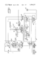
- FIG. 1 is an electrical schematic block diagram of the heat pump and refrigeration system in accordance with the present invention.
- FIG. 2 is a graphical representation of the manner in which the indoor fan speed is controlled in proportion to compressor speed and also as a function of outdoor air temperature.
- FIG. 1 a conditioned space or zone 10, which may be a room or rooms of a residential dwelling, that is provided with a heat pump and refrigeration system designated generally by reference 12.
- the system 12 consists of the conventional reversible heat-pump type which includes a compressor 14, a first heat exchanger 16 located normally outside and away from the conditioned space 10, an expansion device 18 such as a capillary tube, and a second heat exchanger 20 arranged in fluid communication with the zone 10 connected respectively in series to form a closed refrigerant circuit.
- the compressor 14 and the first heat exchanger are housed in an outdoor unit 17 while the expansion device 18 and the second heat exchanger 20 are arranged within an indoor unit 19.
- the first heat exchanger is functioning as an evaporator and the second heat exchanger is operating as a condenser.
- the system may also include a four-way reversing valve 22 for reversing the direction of refrigerant flow in the first and second heat exchangers so that the first heat exchanger can be operated as a condenser and the second heat exchanger can function as an evaporator in a cooling mode during the summer season.
- the manner of controlling the position of the valve 22 may be conventional and is not shown.
- the system 12 is being operated in the heating mode with the heat exchangers 16, 20 being referred to as the evaporator and the condenser, respectively.
- An indoor condenser fan 24 is positioned within the indoor unit 19 in the vicinity of the condenser 20 for circulating air therethrough and into the conditioned space 10.
- An outdoor evaporator fan 26 is also arranged in the outdoor unit 17 adjacent the evaporator 16 for circulating of the air therethrough and out into the atmosphere. The ducts necessary to supply the conditioned air to the space 10 to be heated and to remove the cooled air to the atmosphere have not been shown.
- the compressor 14 is driven by a variable-speed electric motor 28 whose speed is controlled by motor speed control means such as a compressor inverter 30.
- the inverter 30 may be of any conventional type well-known in the art and is utilized to provide an A-C voltage which is of a varying amplitude and frequency. It should be noted that the change in the speed of the motor 28 and thus the compressor speed are directly proportional to changes in the frequency within the standard speeds of operation.
- the indoor condenser fan 24 is also driven by a variable-speed electric motor 29 which is controlled by motor speed control means such as an indoor fan inverter 31.
- the heat pump and refrigeration system 10 is provided with a programmed control means 32 which is responsive in part to the temperatures of the conditioned space 10 as measured continuously by temperature-measuring means consisting of a temperature-sensitive resistance such as thermistor 34.
- the details of the programmed control means 32 will be described more fully hereinafter.
- the control means 32 is also responsive to the desired variable temperature setting or reference temperature of the conditioned space to be heated as determined by thermostat 36 which has been shown schematically.
- the system further includes a data processor designated generally as a microprocessor 38 having a program 40 for controlling the overall operation of the control means 32 in allowing readings of inputs from the thermistor 34 and the thermostat 36.
- a data processor designated generally as a microprocessor 38 having a program 40 for controlling the overall operation of the control means 32 in allowing readings of inputs from the thermistor 34 and the thermostat 36.
- the microprocessor 38 illustrated in FIG. 1 may be of any one of a number of general purpose programmable digital computers which are commonly available at present.
- TMS 1100 One such microcomputer suitable for application in this invention is a microprocessor sold by Texas Instruments designated at TMS 1100 which contains a read-only-memory (ROM), a random-access-memory (RAM), and an arithmetic logic unit (ALU) on a single semiconductor chip.
- ROM read-only-memory
- RAM random-access-memory
- ALU arithmetic logic unit
- a plurality of supplemental electric heaters 41 are arranged above the condenser 20 within the indoor unit 19 to provide supplemental heating when needed. As can be seen, there are shown three stages of supplemental heaters designated respectively at 41a, 41b and 41c which are under the control of the microprocessor 38. In order to conserve and minimize energy consumption, the stages of electric heaters 41 are maintained in the off-condition until it is absolutely necessary to turn them on to supply the desired heating. Prior to turning on of the electric heaters 41, the speed of the compressor is made to run at least up to 150% of rated-speed, which will be described more fully below.
- the thermistor 34 produces an electrical analog signal which is proportional and representative of the present actual measured dry bulb temperature in the conditioned space where the temperature is to be controlled.
- This analog signal is passed through an analog-to-digital (A/D) converter 42 which provides a digital representation of the temperature measured by the thermistor 34 to the control means 32.
- the thermostat 36 provides also an electrical signal, either analog or digital, which is proportional to and representative of the reference temperature or desired temperature setting of the conditioned space 10. If an analog signal is produced from the thermostat 36, it is again sent through an A/D converter 43 to generate a digital representation of the dry bulb temperature setting on the thermostat.
- the programmed control means includes a first summer 44 which adds algebraically the digital representation of the dry bulb set point and the continuously measured temperature to provide an error signal.
- This error signal is fed to a proportional gain amplifier 46 with a gain of Kp (hz/°F.) and an integrator 48 with a transfer function of Ki/s (hz/sec-°F.).
- the digital output from the amplifier 46 and the integrator 48 are added by a second summer 50.
- the digital output of the summer 50 is sent to a digital filter 52 having a transfer function of ##EQU1## wherein w has units of radians/sec.
- the digital output signal of the digital filter 52 is sent to a functional block 56 for determining the speed of the compressor 14 by means of a first functional relation.
- the digital signal from block 56 is passed through D/A converter 57 to produce an analog signal for controlling the speed of the compressor 14 via the compressor inverter 30 and the electric motor 28.
- a second functional relationship in function block 56 sends a digital output signal to the digital-to-analog converter (D/A) or interface 54.
- This digital output signal is a function of the compressor speed determined from the first functional relation and the signal from the adjustment means 58, as shown in detail in FIG. 2 and described below.
- the graph of FIG. 2 illustrates how the indoor coil fan speed is programmed to vary in respect to compressor speed and outdoor air temperature.
- the indoor coil fan speed shown as a percent of rated speed, is represented along the vertical axis or ordinate.
- the compressor speed also expressed as a percent of rated speed, is represented along the horizontal axis or abscissa.
- an adjustment means 58 is provided within the control means to allow an increase in the compressor speed provided the outdoor temperature is below a predetermined temperature.
- a thermistor 60 is included to generate an electrical analog signal representative of the outdoor temperature and is sent through an A/D converter 62 to the adjustment means 58.
- the output of the adjustment means 58 is fed as another input to the function block 56.
- the program 40 controls the reading of inputs from the thermistor 34, thermostat 36 and the thermistor 60 via the respective A/D converters 42, 43 and 62 and provides for calculating of a digital signal for driving the A/D converter 57 to regulate the speed of the compressor.
- the control means is operative to vary the indoor fan motor 29 (during heating) in accordance with the program shown in FIG. 2.
- the proportional gain amplifier 46, the integrater 48 and the second summer 50 provide a control loop with lead compensation for minimizing the error signal from the first summer 44 at steady-state conditions and for cancelling the effect of the lag time in the measured dry bulb temperature reaching the desired condition in response to the change in the compressor speed.
- the digital filter 52 has been designed to remove any spurious noise in the measured temperature and/or in the operation of the A/D converters 42 and 43.
- the operation of the compressor realizes minimal energy consumption, it may not be sufficient to provide enough heat for the conditioned space such as due to the decreasing temperature in the outdoor atmosphere.
- it has been determined that it is better to operate the compressor motor continuously and discretely in the speed range of 25% to a predetermined value in excess of the rated-speed (100% such as up to at least 150% of its full-rated speed or overspeed along the curve B prior to the initiation of supplemental electric heating.
- supplemental electric heaters are not necessary until the outdoor temperature drops below a predetermined temperature such as 50° F. This can be utilized as the set point for the adjustment 58.
- the supplemental heaters 41 are prevented from turning on by the microprocessor 38.
- the digital signal from the functional block 56 will cause the inverter 30 to drive the compressor motor speed to a speed required to match the heating requirement, up to a maximum of at least 150% of its rated-speed, to provide initial supplemental heating via the control mean 32 prior to turning on of the electric heaters.
- the microprocessor allows the operation of one or more stages of electric heaters 41 provided the actual measured temperature of the conditioned space is below the reference temperature and the compressor motor is running at its selected maximum speed.
- the number of stages operating is controlled by the preselected value of the error signal. This can be programmed into the microprocessor 38 so as to cause a sequential turning on of the electric heaters 41a, 41b, and 41c to achieve the desired temperature in the conditioned space. It should be clearly understood by those skilled in the art that while three stages of electric heaters are shown any desired number of electric heaters could be utilized.
- the heat pump and refrigeration system embodying the present invention there is provided an apparatus and method for controlling continuously and discretely the speed of the compressor while varying the speed of the indoor condenser fan in accordance with compressor speed and outdoor air temperature in the heating mode.
- the heat pump and refrigeration system is controlled in its overall operation by a microprocessor having a program to effect control of the measured temperature in a conditioned space.
- the compressor may be operated at least up to 150% of its full rated-speed prior to the initiation of supplemental electric heaters.
- the fan inverter 30 is, in effect, slaved to the compressor inverter 30.
- the thermistor 34 constitutes a first sensing means for measuring the temperature of the conditioned space.
- a reference temperature is set by thermostat 36; and thermistor 60 senses outdoor air temperature.
- the compressor inverter 30 is controlled by a digital signal generated in response to thermistors 34 and 60 and thermostat 36.
- the indoor coil fan is controlled by a second digital signal related to the first digital signal and, in addition, the outdoor air temperature as sensed at 60.
Abstract
Description
Claims (6)
Priority Applications (2)
| Application Number | Priority Date | Filing Date | Title |
|---|---|---|---|
| US06/230,486 US4364237A (en) | 1981-02-02 | 1981-02-02 | Microcomputer control for inverter-driven heat pump |
| CA000395388A CA1176347A (en) | 1981-02-02 | 1982-02-02 | Microcomputer control for inverter-driven heat pump |
Applications Claiming Priority (1)
| Application Number | Priority Date | Filing Date | Title |
|---|---|---|---|
| US06/230,486 US4364237A (en) | 1981-02-02 | 1981-02-02 | Microcomputer control for inverter-driven heat pump |
Publications (1)
| Publication Number | Publication Date |
|---|---|
| US4364237A true US4364237A (en) | 1982-12-21 |
Family
ID=22865413
Family Applications (1)
| Application Number | Title | Priority Date | Filing Date |
|---|---|---|---|
| US06/230,486 Expired - Fee Related US4364237A (en) | 1981-02-02 | 1981-02-02 | Microcomputer control for inverter-driven heat pump |
Country Status (2)
| Country | Link |
|---|---|
| US (1) | US4364237A (en) |
| CA (1) | CA1176347A (en) |
Cited By (54)
| Publication number | Priority date | Publication date | Assignee | Title |
|---|---|---|---|---|
| US4420947A (en) * | 1981-07-10 | 1983-12-20 | System Homes Company, Ltd. | Heat pump air conditioning system |
| US4441901A (en) * | 1981-06-05 | 1984-04-10 | Mitsubishi Denki Kabushiki Kaisha | Heat pump type airconditioner |
| DE3508353A1 (en) * | 1984-03-09 | 1985-09-19 | Hitachi, Ltd., Tokio/Tokyo | METHOD AND DEVICE FOR CONTROLLING AN AIR CONDITIONING SYSTEM WITH A HEAT PUMP |
| US4748822A (en) * | 1986-12-04 | 1988-06-07 | Carrier Corporation | Speed control of a variable speed air conditioning system |
| US4856286A (en) * | 1987-12-02 | 1989-08-15 | American Standard Inc. | Refrigeration compressor driven by a DC motor |
| US4870833A (en) * | 1986-08-27 | 1989-10-03 | Hitachi, Ltd. | Car air conditioning apparatus and controlling method therefor |
| US4891953A (en) * | 1988-02-01 | 1990-01-09 | Mitsubishi Denki Kabushiki Kaisha | Control device for an air conditioner with floor temperature sensor |
| US4930320A (en) * | 1988-05-16 | 1990-06-05 | Honda Giken Kogyo Kabushiki Kaisha | Cooling fan controlling apparatus for vehicle with air conditioner |
| FR2646229A1 (en) * | 1989-04-25 | 1990-10-26 | Abg Semca | Cooling device |
| USRE33620E (en) * | 1987-02-09 | 1991-06-25 | Margaux, Inc. | Continuously variable capacity refrigeration system |
| US5081846A (en) * | 1990-09-21 | 1992-01-21 | Carrier Corporation | Control of space heating and water heating using variable speed heat pump |
| US5099652A (en) * | 1989-12-20 | 1992-03-31 | Kabushiki Kaisha Toshiba | Portable type air conditioning apparatus |
| US5247808A (en) * | 1991-06-17 | 1993-09-28 | Matsushita Electric Industrial Co., Ltd. | Automotive air conditioning apparatus |
| US5255530A (en) * | 1992-11-09 | 1993-10-26 | Whirlpool Corporation | System of two zone refrigerator temperature control |
| US5263335A (en) * | 1991-07-12 | 1993-11-23 | Mitsubishi Denki Kabushiki Kaisha | Operation controller for air conditioner |
| US5275012A (en) * | 1993-01-07 | 1994-01-04 | Ford Motor Company | Climate control system for electric vehicle |
| US5303561A (en) * | 1992-10-14 | 1994-04-19 | Copeland Corporation | Control system for heat pump having humidity responsive variable speed fan |
| EP0599608A2 (en) * | 1992-11-27 | 1994-06-01 | SANYO ELECTRIC Co., Ltd. | Method and apparatus for driving motor |
| US5385030A (en) * | 1993-03-29 | 1995-01-31 | Kabushiki Kaisha Toshiba | Air conditioner |
| EP0655590A1 (en) * | 1993-11-23 | 1995-05-31 | KKW Kulmbacher Klimageräte-Werk GmbH | Compression heat pump and method for operating it |
| US5605053A (en) * | 1994-07-13 | 1997-02-25 | Kabushiki Kaisha Toshiba | Heat pump type air conditioner and method for controlling a heat pump type air conditioner |
| EP0856936A1 (en) * | 1995-10-06 | 1998-08-05 | Hitachi, Ltd. | Motor controller |
| US5823004A (en) * | 1996-11-12 | 1998-10-20 | American Standard Inc. | Outdoor fan control for part load efficiency |
| US6131402A (en) * | 1998-06-03 | 2000-10-17 | Carrier Corporation | Apparatus and method of operating a heat pump to improve heating supply air temperature |
| EP1143147A2 (en) * | 1999-08-13 | 2001-10-10 | Tai-Her Yang | Control of multi stage electrically driven compressor |
| US6603280B2 (en) | 1998-04-02 | 2003-08-05 | Hitachi, Ltd. | Motor controller |
| US20040261441A1 (en) * | 2003-06-26 | 2004-12-30 | Carrier Corporation | Heat pump with improved performance in heating mode |
| US20050268628A1 (en) * | 2004-06-02 | 2005-12-08 | Thompson Thomas W | System and method of increasing efficiency of heat pumps |
| US20050284164A1 (en) * | 2004-06-23 | 2005-12-29 | Denso Corporation | Supercritical heat pump cycle system |
| US20060130504A1 (en) * | 2004-12-17 | 2006-06-22 | Agrawal Nityanand J | Method and apparatus for control of a variable speed compressor |
| US20080135635A1 (en) * | 2006-12-08 | 2008-06-12 | The Hong Kong Polytechnic University | High-low speed control algorithm for direct expansion air-conditioning systems for improved indoor humidity control and energy efficiency |
| EP1985938A1 (en) * | 2006-02-17 | 2008-10-29 | Daikin Industries, Ltd. | Rpm control device, air conditioner, and rpm control method |
| US20090113908A1 (en) * | 2007-10-31 | 2009-05-07 | Lg Electronics Inc. | Method for controlling motor of air conditioner and motor controller of the same |
| US20090308941A1 (en) * | 2008-06-17 | 2009-12-17 | Ronald Harrison Patch | Method and apparatus for control of cooling system air quality and energy consumption |
| CN101526257B (en) * | 2009-03-26 | 2010-11-10 | 宁波海诚电器有限公司 | Method for protecting compressor when air conditioner makes heat in high temperature environment |
| US20110031914A1 (en) * | 2009-08-10 | 2011-02-10 | Emerson Climate Technologies, Inc. | Controller and method for transitioning between control angles |
| US20110031940A1 (en) * | 2009-08-10 | 2011-02-10 | Emerson Climate Technologies, Inc. | System and method for power factor correction frequency tracking and reference generation |
| US20110032738A1 (en) * | 2009-08-10 | 2011-02-10 | Emerson Climate Technologies, Inc. | System and method for power factor correction |
| US20110031920A1 (en) * | 2009-08-10 | 2011-02-10 | Emerson Climate Technologies, Inc. | Controller and method for estimating, managing, and diagnosing motor parameters |
| US20110031941A1 (en) * | 2009-08-10 | 2011-02-10 | Emerson Climate Technologies, Inc. | System and method for current balancing |
| US20110031942A1 (en) * | 2009-08-10 | 2011-02-10 | Emerson Climate Technologies, Inc. | System and method for reducing line current distortion |
| US20110031911A1 (en) * | 2009-08-10 | 2011-02-10 | Emerson Climate Technologies, Inc. | Power factor correction with variable bus voltage |
| US20110031943A1 (en) * | 2009-08-10 | 2011-02-10 | Emerson Climate Technologies, Inc. | System and method for rejecting dc current in power factor correction systems |
| US20140096547A1 (en) * | 2012-10-10 | 2014-04-10 | Trane International Inc. | Variable fan speed control in hvac systems and methods |
| US8698433B2 (en) | 2009-08-10 | 2014-04-15 | Emerson Climate Technologies, Inc. | Controller and method for minimizing phase advance current |
| CN104236010A (en) * | 2013-06-20 | 2014-12-24 | 广东美的集团芜湖制冷设备有限公司 | Control method of air conditioner |
| US20150158369A1 (en) * | 2013-12-05 | 2015-06-11 | Ford Global Technologies, Llc | Method for adjusting fan and compressor power for a vehicle cabin heating system |
| US20150253050A1 (en) * | 2014-03-05 | 2015-09-10 | Lennox Industries Inc. | A heat pump system having a maximum percent demand re-calculation algorithm controller |
| US9240749B2 (en) | 2012-08-10 | 2016-01-19 | Emerson Climate Technologies, Inc. | Motor drive control using pulse-width modulation pulse skipping |
| US9634593B2 (en) | 2012-04-26 | 2017-04-25 | Emerson Climate Technologies, Inc. | System and method for permanent magnet motor control |
| EP3101362A4 (en) * | 2014-01-28 | 2017-11-15 | Daikin Industries, Ltd. | Air-conditioning device |
| US10310475B2 (en) | 2015-10-09 | 2019-06-04 | Carrier Corporation | System and method of operating a variable speed HVAC system |
| US10724753B2 (en) | 2015-12-29 | 2020-07-28 | Carrier Corporation | System and method for operating a variable speed compressor |
| US10895412B2 (en) * | 2018-07-11 | 2021-01-19 | Mitsubishi Electric Research Laboratories, Inc. | System and method for power optimizing control of multi-zone heat pumps |
Citations (3)
| Publication number | Priority date | Publication date | Assignee | Title |
|---|---|---|---|---|
| US3324672A (en) * | 1964-08-31 | 1967-06-13 | Gen Motors Corp | Electrically controlled conditioning system |
| US4257238A (en) * | 1979-09-28 | 1981-03-24 | Borg-Warner Corporation | Microcomputer control for an inverter-driven heat pump |
| US4269261A (en) * | 1979-09-28 | 1981-05-26 | Borg-Warner Corporation | Microcomputer control for supplemental heating in a heat pump |
-
1981
- 1981-02-02 US US06/230,486 patent/US4364237A/en not_active Expired - Fee Related
-
1982
- 1982-02-02 CA CA000395388A patent/CA1176347A/en not_active Expired
Patent Citations (3)
| Publication number | Priority date | Publication date | Assignee | Title |
|---|---|---|---|---|
| US3324672A (en) * | 1964-08-31 | 1967-06-13 | Gen Motors Corp | Electrically controlled conditioning system |
| US4257238A (en) * | 1979-09-28 | 1981-03-24 | Borg-Warner Corporation | Microcomputer control for an inverter-driven heat pump |
| US4269261A (en) * | 1979-09-28 | 1981-05-26 | Borg-Warner Corporation | Microcomputer control for supplemental heating in a heat pump |
Cited By (95)
| Publication number | Priority date | Publication date | Assignee | Title |
|---|---|---|---|---|
| US4441901A (en) * | 1981-06-05 | 1984-04-10 | Mitsubishi Denki Kabushiki Kaisha | Heat pump type airconditioner |
| US4420947A (en) * | 1981-07-10 | 1983-12-20 | System Homes Company, Ltd. | Heat pump air conditioning system |
| DE3508353A1 (en) * | 1984-03-09 | 1985-09-19 | Hitachi, Ltd., Tokio/Tokyo | METHOD AND DEVICE FOR CONTROLLING AN AIR CONDITIONING SYSTEM WITH A HEAT PUMP |
| US4603556A (en) * | 1984-03-09 | 1986-08-05 | Hitachi, Ltd. | Control method and apparatus for an air conditioner using a heat pump |
| US4870833A (en) * | 1986-08-27 | 1989-10-03 | Hitachi, Ltd. | Car air conditioning apparatus and controlling method therefor |
| US4748822A (en) * | 1986-12-04 | 1988-06-07 | Carrier Corporation | Speed control of a variable speed air conditioning system |
| USRE33620E (en) * | 1987-02-09 | 1991-06-25 | Margaux, Inc. | Continuously variable capacity refrigeration system |
| US4856286A (en) * | 1987-12-02 | 1989-08-15 | American Standard Inc. | Refrigeration compressor driven by a DC motor |
| US4891953A (en) * | 1988-02-01 | 1990-01-09 | Mitsubishi Denki Kabushiki Kaisha | Control device for an air conditioner with floor temperature sensor |
| US4930320A (en) * | 1988-05-16 | 1990-06-05 | Honda Giken Kogyo Kabushiki Kaisha | Cooling fan controlling apparatus for vehicle with air conditioner |
| FR2646229A1 (en) * | 1989-04-25 | 1990-10-26 | Abg Semca | Cooling device |
| US5099652A (en) * | 1989-12-20 | 1992-03-31 | Kabushiki Kaisha Toshiba | Portable type air conditioning apparatus |
| US5081846A (en) * | 1990-09-21 | 1992-01-21 | Carrier Corporation | Control of space heating and water heating using variable speed heat pump |
| US5247808A (en) * | 1991-06-17 | 1993-09-28 | Matsushita Electric Industrial Co., Ltd. | Automotive air conditioning apparatus |
| US5263335A (en) * | 1991-07-12 | 1993-11-23 | Mitsubishi Denki Kabushiki Kaisha | Operation controller for air conditioner |
| US5303561A (en) * | 1992-10-14 | 1994-04-19 | Copeland Corporation | Control system for heat pump having humidity responsive variable speed fan |
| US5255530A (en) * | 1992-11-09 | 1993-10-26 | Whirlpool Corporation | System of two zone refrigerator temperature control |
| EP0599608A2 (en) * | 1992-11-27 | 1994-06-01 | SANYO ELECTRIC Co., Ltd. | Method and apparatus for driving motor |
| EP0599608A3 (en) * | 1992-11-27 | 1995-05-03 | Sanyo Electric Co | Method and apparatus for driving motor. |
| US5528114A (en) * | 1992-11-27 | 1996-06-18 | Sanyo Electric Co., Ltd. | Apparatus for driving two motors |
| US5275012A (en) * | 1993-01-07 | 1994-01-04 | Ford Motor Company | Climate control system for electric vehicle |
| US5385030A (en) * | 1993-03-29 | 1995-01-31 | Kabushiki Kaisha Toshiba | Air conditioner |
| EP0655590A1 (en) * | 1993-11-23 | 1995-05-31 | KKW Kulmbacher Klimageräte-Werk GmbH | Compression heat pump and method for operating it |
| US5605053A (en) * | 1994-07-13 | 1997-02-25 | Kabushiki Kaisha Toshiba | Heat pump type air conditioner and method for controlling a heat pump type air conditioner |
| EP0856936A1 (en) * | 1995-10-06 | 1998-08-05 | Hitachi, Ltd. | Motor controller |
| EP0856936A4 (en) * | 1995-10-06 | 1999-11-10 | Hitachi Ltd | Motor controller |
| US6198240B1 (en) | 1995-10-06 | 2001-03-06 | Hitachi, Ltd. | Motor controller |
| US5823004A (en) * | 1996-11-12 | 1998-10-20 | American Standard Inc. | Outdoor fan control for part load efficiency |
| US6603280B2 (en) | 1998-04-02 | 2003-08-05 | Hitachi, Ltd. | Motor controller |
| US6131402A (en) * | 1998-06-03 | 2000-10-17 | Carrier Corporation | Apparatus and method of operating a heat pump to improve heating supply air temperature |
| EP0962715A3 (en) * | 1998-06-03 | 2002-08-28 | Carrier Corporation | Apparatus and method of operating a heat pump to improve heating supply air temperature |
| EP1143147A2 (en) * | 1999-08-13 | 2001-10-10 | Tai-Her Yang | Control of multi stage electrically driven compressor |
| US6336337B1 (en) * | 1999-08-13 | 2002-01-08 | Tai-Her Yang | Multi-stage compressor pump driving system for air conditioning and refrigeration applications |
| EP1143147A3 (en) * | 1999-08-13 | 2002-04-03 | Tai-Her Yang | Control of multi stage electrically driven compressor |
| US20040261441A1 (en) * | 2003-06-26 | 2004-12-30 | Carrier Corporation | Heat pump with improved performance in heating mode |
| WO2005001344A1 (en) * | 2003-06-26 | 2005-01-06 | Carrier Corporation | Heat pump with improved performance in heating mode |
| US6907745B2 (en) * | 2003-06-26 | 2005-06-21 | Carrier Corporation | Heat pump with improved performance in heating mode |
| US20050268628A1 (en) * | 2004-06-02 | 2005-12-08 | Thompson Thomas W | System and method of increasing efficiency of heat pumps |
| US7340910B2 (en) | 2004-06-02 | 2008-03-11 | Thompson Thomas W | System and method of increasing efficiency of heat pumps |
| US20050284164A1 (en) * | 2004-06-23 | 2005-12-29 | Denso Corporation | Supercritical heat pump cycle system |
| US7559206B2 (en) * | 2004-06-23 | 2009-07-14 | Denso Corporation | Supercritical heat pump cycle system |
| US20060130504A1 (en) * | 2004-12-17 | 2006-06-22 | Agrawal Nityanand J | Method and apparatus for control of a variable speed compressor |
| EP1985938A1 (en) * | 2006-02-17 | 2008-10-29 | Daikin Industries, Ltd. | Rpm control device, air conditioner, and rpm control method |
| EP1985938A4 (en) * | 2006-02-17 | 2013-03-06 | Daikin Ind Ltd | Rpm control device, air conditioner, and rpm control method |
| US20080135635A1 (en) * | 2006-12-08 | 2008-06-12 | The Hong Kong Polytechnic University | High-low speed control algorithm for direct expansion air-conditioning systems for improved indoor humidity control and energy efficiency |
| US20090113908A1 (en) * | 2007-10-31 | 2009-05-07 | Lg Electronics Inc. | Method for controlling motor of air conditioner and motor controller of the same |
| US8234879B2 (en) * | 2007-10-31 | 2012-08-07 | Lg Electronics Inc. | Method for controlling motor of air conditioner and motor controller of the same |
| US20090308941A1 (en) * | 2008-06-17 | 2009-12-17 | Ronald Harrison Patch | Method and apparatus for control of cooling system air quality and energy consumption |
| US7918407B2 (en) | 2008-06-17 | 2011-04-05 | Ronald Harrison Patch | Method and apparatus for control of cooling system air quality and energy consumption |
| CN101526257B (en) * | 2009-03-26 | 2010-11-10 | 宁波海诚电器有限公司 | Method for protecting compressor when air conditioner makes heat in high temperature environment |
| US9088232B2 (en) | 2009-08-10 | 2015-07-21 | Emerson Climate Technologies, Inc. | Power factor correction with variable bus voltage |
| US8493014B2 (en) | 2009-08-10 | 2013-07-23 | Emerson Climate Technologies, Inc. | Controller and method for estimating, managing, and diagnosing motor parameters |
| US20110031942A1 (en) * | 2009-08-10 | 2011-02-10 | Emerson Climate Technologies, Inc. | System and method for reducing line current distortion |
| US20110031920A1 (en) * | 2009-08-10 | 2011-02-10 | Emerson Climate Technologies, Inc. | Controller and method for estimating, managing, and diagnosing motor parameters |
| US20110031943A1 (en) * | 2009-08-10 | 2011-02-10 | Emerson Climate Technologies, Inc. | System and method for rejecting dc current in power factor correction systems |
| US20110032738A1 (en) * | 2009-08-10 | 2011-02-10 | Emerson Climate Technologies, Inc. | System and method for power factor correction |
| WO2011019701A3 (en) * | 2009-08-10 | 2011-06-23 | Emerson Climate Technologies, Inc. | Power factor correction with variable bus voltage |
| US20110031940A1 (en) * | 2009-08-10 | 2011-02-10 | Emerson Climate Technologies, Inc. | System and method for power factor correction frequency tracking and reference generation |
| US8264860B2 (en) | 2009-08-10 | 2012-09-11 | Emerson Climate Technologies, Inc. | System and method for power factor correction frequency tracking and reference generation |
| US8264192B2 (en) | 2009-08-10 | 2012-09-11 | Emerson Climate Technologies, Inc. | Controller and method for transitioning between control angles |
| US8344706B2 (en) | 2009-08-10 | 2013-01-01 | Emerson Climate Technologies, Inc. | System and method for rejecting DC current in power factor correction systems |
| US8358098B2 (en) | 2009-08-10 | 2013-01-22 | Emerson Climate Technologies, Inc. | System and method for power factor correction |
| US20110031914A1 (en) * | 2009-08-10 | 2011-02-10 | Emerson Climate Technologies, Inc. | Controller and method for transitioning between control angles |
| US8406021B2 (en) | 2009-08-10 | 2013-03-26 | Emerson Climate Technologies, Inc. | System and method for reducing line current distortion |
| US8476873B2 (en) | 2009-08-10 | 2013-07-02 | Emerson Climate Technologies, Inc. | System and method for current balancing |
| US9705433B2 (en) | 2009-08-10 | 2017-07-11 | Emerson Climate Technologies, Inc. | Controller and method for transitioning between control angles |
| US8508166B2 (en) | 2009-08-10 | 2013-08-13 | Emerson Climate Technologies, Inc. | Power factor correction with variable bus voltage |
| US9154061B2 (en) | 2009-08-10 | 2015-10-06 | Emerson Climate Technologies, Inc. | Controller and method for transitioning between control angles |
| US9564846B2 (en) | 2009-08-10 | 2017-02-07 | Emerson Climate Technologies, Inc. | Power factor correction with variable bus voltage |
| US8698433B2 (en) | 2009-08-10 | 2014-04-15 | Emerson Climate Technologies, Inc. | Controller and method for minimizing phase advance current |
| US8547051B2 (en) | 2009-08-10 | 2013-10-01 | Emerson Climate Technologies, Inc. | Controller and method for transitioning between control angles |
| US9912263B2 (en) | 2009-08-10 | 2018-03-06 | Emerson Climate Technologies, Inc. | Controller and method for transitioning between control angles |
| US20110031911A1 (en) * | 2009-08-10 | 2011-02-10 | Emerson Climate Technologies, Inc. | Power factor correction with variable bus voltage |
| US20110031941A1 (en) * | 2009-08-10 | 2011-02-10 | Emerson Climate Technologies, Inc. | System and method for current balancing |
| US9991834B2 (en) | 2012-04-26 | 2018-06-05 | Emerson Climate Technologies, Inc. | System and method for permanent magnet motor control |
| US10075116B2 (en) | 2012-04-26 | 2018-09-11 | Emerson Climate Technologies, Inc. | System and method for permanent magnet motor control |
| US9634593B2 (en) | 2012-04-26 | 2017-04-25 | Emerson Climate Technologies, Inc. | System and method for permanent magnet motor control |
| US9240749B2 (en) | 2012-08-10 | 2016-01-19 | Emerson Climate Technologies, Inc. | Motor drive control using pulse-width modulation pulse skipping |
| US9853588B2 (en) | 2012-08-10 | 2017-12-26 | Emerson Climate Technologies, Inc. | Motor drive control using pulse-width modulation pulse skipping |
| US10760841B2 (en) | 2012-10-10 | 2020-09-01 | Trane International Inc. | Variable fan speed control in HVAC systems and methods |
| US20140096547A1 (en) * | 2012-10-10 | 2014-04-10 | Trane International Inc. | Variable fan speed control in hvac systems and methods |
| US9810469B2 (en) * | 2012-10-10 | 2017-11-07 | Trane International Inc. | Variable fan speed control in HVAC systems and methods |
| CN104236010A (en) * | 2013-06-20 | 2014-12-24 | 广东美的集团芜湖制冷设备有限公司 | Control method of air conditioner |
| CN104236010B (en) * | 2013-06-20 | 2017-02-22 | 广东美的集团芜湖制冷设备有限公司 | Control method of air conditioner |
| US20150158369A1 (en) * | 2013-12-05 | 2015-06-11 | Ford Global Technologies, Llc | Method for adjusting fan and compressor power for a vehicle cabin heating system |
| US9702605B2 (en) * | 2013-12-05 | 2017-07-11 | Ford Global Technologies, Llc | Method for adjusting fan and compressor power for a vehicle cabin heating system |
| EP3101362A4 (en) * | 2014-01-28 | 2017-11-15 | Daikin Industries, Ltd. | Air-conditioning device |
| US10161651B2 (en) | 2014-01-28 | 2018-12-25 | Daikin Industries, Ltd. | Air conditioning apparatus |
| US20170336117A1 (en) * | 2014-03-05 | 2017-11-23 | Lennox Industries Inc. | Heat pump system having a maximum percent demand re-calculation algorithm controller |
| US9759466B2 (en) * | 2014-03-05 | 2017-09-12 | Lennox Industries Inc. | Heat pump system having a maximum percent demand re-calculation algorithm controller |
| US10215464B2 (en) * | 2014-03-05 | 2019-02-26 | Lennox Industries Inc. | Heat pump system having a maximum percent demand re-calculation algorithm controller |
| US20150253050A1 (en) * | 2014-03-05 | 2015-09-10 | Lennox Industries Inc. | A heat pump system having a maximum percent demand re-calculation algorithm controller |
| US10310475B2 (en) | 2015-10-09 | 2019-06-04 | Carrier Corporation | System and method of operating a variable speed HVAC system |
| US10724753B2 (en) | 2015-12-29 | 2020-07-28 | Carrier Corporation | System and method for operating a variable speed compressor |
| US10895412B2 (en) * | 2018-07-11 | 2021-01-19 | Mitsubishi Electric Research Laboratories, Inc. | System and method for power optimizing control of multi-zone heat pumps |
Also Published As
| Publication number | Publication date |
|---|---|
| CA1176347A (en) | 1984-10-16 |
Similar Documents
| Publication | Publication Date | Title |
|---|---|---|
| US4364237A (en) | Microcomputer control for inverter-driven heat pump | |
| US4269261A (en) | Microcomputer control for supplemental heating in a heat pump | |
| US4257238A (en) | Microcomputer control for an inverter-driven heat pump | |
| US4353409A (en) | Apparatus and method for controlling a variable air volume temperature conditioning system | |
| US4748822A (en) | Speed control of a variable speed air conditioning system | |
| US5062276A (en) | Humidity control for variable speed air conditioner | |
| CA1164970A (en) | Microprocessor discharge temperature air controller for multi-stage heating and/or cooling apparatus and outdoor air usage controller | |
| US4889280A (en) | Temperature and humidity auctioneering control | |
| US5319943A (en) | Frost/defrost control system for heat pump | |
| US5052186A (en) | Control of outdoor air source water heating using variable-speed heat pump | |
| US4265299A (en) | Heat pump control system | |
| US4393662A (en) | Control system for refrigeration or air conditioning installation | |
| US5076346A (en) | Air conditioner | |
| KR970006058B1 (en) | Method and apparatus for controlling temperature in airconditioner | |
| US4498310A (en) | Heat pump system | |
| US5823004A (en) | Outdoor fan control for part load efficiency | |
| JPS60200037A (en) | Controller for temperature regulating system and method thereof | |
| US20150338111A1 (en) | Variable Speed Outdoor Fan Control | |
| US20170030621A1 (en) | Low ambient cooling scheme and control | |
| US20050087616A1 (en) | Thermal balance temperature control system | |
| US6089464A (en) | Thermal dynamic balancer | |
| US3250084A (en) | Control systems | |
| US4178764A (en) | Air conditioning system | |
| US4836095A (en) | Static pressure control in variable air volume delivery system | |
| GB2059646A (en) | Microcomputer control for supplemental heating in a heat pump |
Legal Events
| Date | Code | Title | Description |
|---|---|---|---|
| AS | Assignment |
Owner name: BORG-WARNER CORPORATION, 200 SOUTH MICHIGAN AVE., Free format text: ASSIGNMENT OF ASSIGNORS INTEREST.;ASSIGNORS:COOPER KENNETH W.;SHAFFER JACOB E. JR.;REEL/FRAME:003862/0072 Effective date: 19810130 |
|
| MAFP | Maintenance fee payment |
Free format text: PAYMENT OF MAINTENANCE FEE, 4TH YEAR, PL 96-517 (ORIGINAL EVENT CODE: M170); ENTITY STATUS OF PATENT OWNER: LARGE ENTITY Year of fee payment: 4 |
|
| AS | Assignment |
Owner name: YORK INTERNATIONAL CORPORATION, 631 SOUTH RICHLAN Free format text: ASSIGNMENT OF ASSIGNORS INTEREST. EFFECTIVE;ASSIGNOR:BORG-WARNER CORPORATION;REEL/FRAME:004676/0360 Effective date: 19860609 |
|
| AS | Assignment |
Owner name: CANADIAN IMPERIAL BANK OF COMMERCE Free format text: SECURITY INTEREST;ASSIGNOR:YORK INTERNATIONAL CORPORATION;REEL/FRAME:005156/0705 Effective date: 19881215 |
|
| FEPP | Fee payment procedure |
Free format text: MAINTENANCE FEE REMINDER MAILED (ORIGINAL EVENT CODE: REM.); ENTITY STATUS OF PATENT OWNER: LARGE ENTITY |
|
| LAPS | Lapse for failure to pay maintenance fees | ||
| STCH | Information on status: patent discontinuation |
Free format text: PATENT EXPIRED DUE TO NONPAYMENT OF MAINTENANCE FEES UNDER 37 CFR 1.362 |
|
| FP | Lapsed due to failure to pay maintenance fee |
Effective date: 19901223 |
|
| AS | Assignment |
Owner name: CANADIAN IMPERIAL BANK OF COMMERCE Free format text: SECURITY INTEREST;ASSIGNOR:YORK OPERATING COMPANY, F/K/A YORK INTERNATIONAL CORPORATION A DE CORP.;REEL/FRAME:005994/0916 Effective date: 19911009 |
|
| AS | Assignment |
Owner name: CANADIAN IMPERIAL BANK OF COMMERCE Free format text: SECURITY INTEREST;ASSIGNOR:YORK INTERNATIONAL CORPORATION (F/K/A YORK OPERATING COMPANY);REEL/FRAME:006007/0123 Effective date: 19911231 |
|
| AS | Assignment |
Owner name: CANADIAN IMPERIAL BANK OF COMMERCE Free format text: RELEASED BY SECURED PARTY;ASSIGNOR:YORK INTERNATIONAL CORPORATION, A DE CORP.;REEL/FRAME:006194/0182 Effective date: 19920630 |