US4365343A - Counterweighted X-ray tube - Google Patents
Counterweighted X-ray tube Download PDFInfo
- Publication number
- US4365343A US4365343A US06/203,963 US20396380A US4365343A US 4365343 A US4365343 A US 4365343A US 20396380 A US20396380 A US 20396380A US 4365343 A US4365343 A US 4365343A
- Authority
- US
- United States
- Prior art keywords
- radiation
- arm
- counterweight
- lever
- support
- Prior art date
- Legal status (The legal status is an assumption and is not a legal conclusion. Google has not performed a legal analysis and makes no representation as to the accuracy of the status listed.)
- Expired - Lifetime
Links
Images
Classifications
-
- A—HUMAN NECESSITIES
- A61—MEDICAL OR VETERINARY SCIENCE; HYGIENE
- A61B—DIAGNOSIS; SURGERY; IDENTIFICATION
- A61B6/00—Apparatus for radiation diagnosis, e.g. combined with radiation therapy equipment
- A61B6/44—Constructional features of apparatus for radiation diagnosis
- A61B6/4429—Constructional features of apparatus for radiation diagnosis related to the mounting of source units and detector units
- A61B6/4435—Constructional features of apparatus for radiation diagnosis related to the mounting of source units and detector units the source unit and the detector unit being coupled by a rigid structure
- A61B6/4441—Constructional features of apparatus for radiation diagnosis related to the mounting of source units and detector units the source unit and the detector unit being coupled by a rigid structure the rigid structure being a C-arm or U-arm
-
- A—HUMAN NECESSITIES
- A61—MEDICAL OR VETERINARY SCIENCE; HYGIENE
- A61B—DIAGNOSIS; SURGERY; IDENTIFICATION
- A61B6/00—Apparatus for radiation diagnosis, e.g. combined with radiation therapy equipment
- A61B6/44—Constructional features of apparatus for radiation diagnosis
- A61B6/4429—Constructional features of apparatus for radiation diagnosis related to the mounting of source units and detector units
- A61B6/447—Constructional features of apparatus for radiation diagnosis related to the mounting of source units and detector units the source unit or the detector unit being mounted to counterpoise or springs
Definitions
- This invention relates to X-ray apparatus in which the X-radiation tube and the image intensifier or other radiation receptor are mounted at the ends of two parallel arms of a generally U-shaped support such as is shown in U.S. Pat. No. 3,892,967.
- the two radiation means are optically aligned on a common radiation axis.
- the U-shaped support is turned in a bearing about a rotational axis parallel to the arms on which the X-ray tube and radiation receptor are mounted and through which the radiation axis passes.
- Adjustable counterweighting may be achieved by moving sliding weights on cables or the like as shown in the aforementioned patent. However, if both the radiation source and receptor are to be adjusted, there may be insufficient space for the counterbalancing system on or in the arms of the U-shaped support.
- radiological apparatus comprises a support; and radiation source means and radiation receptor means at spaced positions on the support for examination of a subject at a location therebetween, the source and receptor means having a common radiation axis extending through the subject location, and each means being mounted on the support to move along the radiation axis; wherein the support includes an arm extending to one radiation means toward the radiation axis; means on the arm guiding the radiation means along the radiation axis; fulcrum means on the arm; a lever pivoted on the fulcrum means and pivotally attached at one end to the radiation means; and a counterweight guided on the arm and engaging the other end of the lever to counterbalance the radiation means.
- the arm is hollow and the counterweight is contained within the arm and guided transversely of the arm.
- FIG. 1 is an isometric view of radiological apparatus having a counter balancing system according to the invention
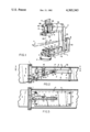
- FIG. 2 is a side section of the counter balancing system
- FIG. 3 is a plan view of a counterweight in the system.
- the X-ray apparatus in FIG. 1 comprises a support including an L-shaped base L with a horizontal arm La swinging on a pivot assembly P, and an upright arm Lb extending at right angles to the horizontal arm.
- a heavy bearing B At the upper end of the upright arm Lb is a heavy bearing B in which a U-shaped part of the support rotates about an axis A1.
- the U-shaped support part comprises a vertical arm Uc and an upper horizontal arm Ua and a lower, hollow arm Ub having upper and lower walls 4 and 6, and side walls 7.
- a housing X for an X-ray tube which is a radiation source.
- a radiation receptor At the end of the upper arm Ua is a radiation receptor, namely a radiation image intensifier II which electronically intensifies the X-ray image and projects the intensified image on a beam splitter BS allowing the image to be recorded or transmitted by a still camera SC, a motion picture camera MC and a television camera TV.
- a radiation image intensifier II which electronically intensifies the X-ray image and projects the intensified image on a beam splitter BS allowing the image to be recorded or transmitted by a still camera SC, a motion picture camera MC and a television camera TV.
- Another radiation receptor such as a film holder or changer FC.
- the image intensifier II and X-ray tube define a radiation axis A2 which intersects the axis Al of the U-shaped support part U at an isocenter C.
- the isocenter C is also the location of the subject of radiological examination.
- the subject is usually a patient lying on a table T which slides on rails R supported on a standard S.
- the radiation source housing X and the two radiation receptors II and FC are slidingly mounted on the upper and lower arms Ua and Ub respectively so that they can be moved up and down along the radiation axis A2.
- the film changer FC can also move transversely of the guides G out of the way of the image intensifier so that either the film changer or image intensifier can be the active radiation receptor. To keep the image intensifier close to the radiation image plane it is desirable to move the image intensifier together with the film changer even though the image intensifier is not active as a radiation receptor.
- the X-ray tube housing X is guided in its reciprocation along the radiation axis A2 by tracks 1 at the free end of the lower support arm Ub.
- a counterweight 2 for the X-ray tube and housing X slides on four vertical guide rods 3 which are anchored to the upper wall 4 and lower wall 6 of the arm Ub.
- the counterweight 2 comprises a steel frame 8 holding a lead core 9.
- a first order lever 11 has a medial slot 12 which slides on the roller 13 of a fulcrum 14.
- the fulcrum 14 is supported on a hanger 16 depending from the upper wall 4 of the lower support arm Ub.
- the counterweight end of the lever forms a fork 17 sliding on the roller 18 of a pivot 19 anchored at the center of gravity of the counterweight.
- the other end of the lever 11 is attached by a pivot pin 21 to a bracket 22 attached to the X-ray tube housing X.
- the X-ray tube housing With the lever slidingly connecting the X-ray tube housing X and the counterweight 2 the X-ray tube housing is very closely counterbalanced in all up and down positions of the counterweight transversely of the upper and lower walls 4, 6 of the arm Ub.
- the X-ray tube counter balancing system is entirely adjacent the free end of the arm Ub and is directly connected to the X-ray tube housing rather than being connected by cables to counterweights in the vertical arm Uc as in previous systems. This compact localized counterweight system does not interfere or compete for space with counterweight systems for the radiation receptors II and FC.
Abstract
X-ray apparatus comprises a U-shaped support having two hollow, horizontal arms. On the end of one arm is mounted an X-ray tube and on the other an X-radiation receptor both guided for movement on a radiation axis.
A counterweight within one hollow, horizontal arm is guided for movement parallel to the X-ray tube, transversely of the arm. To counterbalance the X-ray tube a lever attached to the tube has sliding pivots at a fulcrum and the counterweight allowing the lever arm to change its length without changing the leverage ratio.
Description
This invention relates to X-ray apparatus in which the X-radiation tube and the image intensifier or other radiation receptor are mounted at the ends of two parallel arms of a generally U-shaped support such as is shown in U.S. Pat. No. 3,892,967. The two radiation means are optically aligned on a common radiation axis. In radiological examination of a subject the U-shaped support is turned in a bearing about a rotational axis parallel to the arms on which the X-ray tube and radiation receptor are mounted and through which the radiation axis passes. It is necessary that the rotating assembly of U-shaped support and radiation source and receptor be kept in balance with respect to the rotational axis to reduce bearing friction, to allow the assembly to rest motionless in equilibrium, and also to permit manual rotation of the assembly. On the other hand it is desirable to adjust the X-ray tube along the radiation axis toward and away from the rotational axis which would destroy the equilibrium of the assembly unless adjustment of the X-ray tube weight is compensated by adjustable counterweighting.
Adjustable counterweighting may be achieved by moving sliding weights on cables or the like as shown in the aforementioned patent. However, if both the radiation source and receptor are to be adjusted, there may be insufficient space for the counterbalancing system on or in the arms of the U-shaped support.
Accordingly it is the object of the present invention to provide a counterbalancing system which requires a minimum of space and allows counterbalancing of both the radiation source and the radiation receptor.
According to the invention radiological apparatus comprises a support; and radiation source means and radiation receptor means at spaced positions on the support for examination of a subject at a location therebetween, the source and receptor means having a common radiation axis extending through the subject location, and each means being mounted on the support to move along the radiation axis; wherein the support includes an arm extending to one radiation means toward the radiation axis; means on the arm guiding the radiation means along the radiation axis; fulcrum means on the arm; a lever pivoted on the fulcrum means and pivotally attached at one end to the radiation means; and a counterweight guided on the arm and engaging the other end of the lever to counterbalance the radiation means.
Further according to the invention the arm is hollow and the counterweight is contained within the arm and guided transversely of the arm.
FIG. 1 is an isometric view of radiological apparatus having a counter balancing system according to the invention;
FIG. 2 is a side section of the counter balancing system; and
FIG. 3 is a plan view of a counterweight in the system.
The X-ray apparatus in FIG. 1 comprises a support including an L-shaped base L with a horizontal arm La swinging on a pivot assembly P, and an upright arm Lb extending at right angles to the horizontal arm. At the upper end of the upright arm Lb is a heavy bearing B in which a U-shaped part of the support rotates about an axis A1. The U-shaped support part comprises a vertical arm Uc and an upper horizontal arm Ua and a lower, hollow arm Ub having upper and lower walls 4 and 6, and side walls 7. At the end of the lower arm Ub is a housing X for an X-ray tube which is a radiation source. At the end of the upper arm Ua is a radiation receptor, namely a radiation image intensifier II which electronically intensifies the X-ray image and projects the intensified image on a beam splitter BS allowing the image to be recorded or transmitted by a still camera SC, a motion picture camera MC and a television camera TV. Below the image intensifier II is another radiation receptor such as a film holder or changer FC. The image intensifier II and X-ray tube define a radiation axis A2 which intersects the axis Al of the U-shaped support part U at an isocenter C. The isocenter C is also the location of the subject of radiological examination. The subject is usually a patient lying on a table T which slides on rails R supported on a standard S.
The radiation source housing X and the two radiation receptors II and FC are slidingly mounted on the upper and lower arms Ua and Ub respectively so that they can be moved up and down along the radiation axis A2. The film changer FC can also move transversely of the guides G out of the way of the image intensifier so that either the film changer or image intensifier can be the active radiation receptor. To keep the image intensifier close to the radiation image plane it is desirable to move the image intensifier together with the film changer even though the image intensifier is not active as a radiation receptor.
The X-ray tube housing X is guided in its reciprocation along the radiation axis A2 by tracks 1 at the free end of the lower support arm Ub. A counterweight 2 for the X-ray tube and housing X slides on four vertical guide rods 3 which are anchored to the upper wall 4 and lower wall 6 of the arm Ub. The counterweight 2 comprises a steel frame 8 holding a lead core 9. A first order lever 11 has a medial slot 12 which slides on the roller 13 of a fulcrum 14. The fulcrum 14 is supported on a hanger 16 depending from the upper wall 4 of the lower support arm Ub. The counterweight end of the lever forms a fork 17 sliding on the roller 18 of a pivot 19 anchored at the center of gravity of the counterweight. The other end of the lever 11 is attached by a pivot pin 21 to a bracket 22 attached to the X-ray tube housing X.
With the lever slidingly connecting the X-ray tube housing X and the counterweight 2 the X-ray tube housing is very closely counterbalanced in all up and down positions of the counterweight transversely of the upper and lower walls 4, 6 of the arm Ub. The X-ray tube counter balancing system is entirely adjacent the free end of the arm Ub and is directly connected to the X-ray tube housing rather than being connected by cables to counterweights in the vertical arm Uc as in previous systems. This compact localized counterweight system does not interfere or compete for space with counterweight systems for the radiation receptors II and FC. It should be noted that in the horizontal arm Ub the guide means for the X-ray tube housing X and the counterweight 2, namely the tracks 1 and the guide rods 3, guide the housing and counterweight on parallel (vertical) paths. Ordinary fixed pivots for the lever 11 would not allow such movement but the fulcrum 14 and pivot 19 are slidingly engaged by the lever allowing the effective lever length to change, but without changing the half lever length to either side of the fulcrum, i.e. the leverage ratio.
It should be understood that the present disclosure is for the purpose of illustration only and that this invention includes all modifications and equivalents which fall within the scope of the appended claims.
Claims (8)
1. Radiological apparatus comprising:
a support; and
radiation source means and radiation receptor means at spaced positions on the support for examination of a subject at a location therebetween, the source and receptor means having a common radiation axis extending through the subject location, and each means being mounted on the support to move along the radiation axis;
wherein the support includes
an arm extending to one radiation means toward the radiation axis;
means on the arm guiding the radiation means along the radiation axis;
fulcrum means on the arm;
a lever pivoted on the fulcrum means and pivotally attached at one end to the radiation means; and
a counterweight guided on the arm and engaging the other end of the lever to counterbalance the radiation means.
2. Apparatus according to claim 1 wherein the support is U-shaped and includes two generally parallel arms, the radiation means being mounted on respective arms.
3. Apparatus according to claim 2 wherein one arm is hollow and the counterweight is contained within the arm.
4. Aparatus according to claim 3 wherein the hollow arm is horizontal.
5. Apparatus according to claim 1 or 3 wherein the counterweight is guided transversely of the arm.
6. Apparatus according to claim 1 wherein the fulcrum makes sliding engagement with the lever.
7. Apparatus according to claim 1 wherein the counterweight slidingly engages the lever.
8. Apparatus according to claim 1 including means guiding the radiation means and counterweight on parallel paths, wherein the fulcrum, the lever attachment to the radiation means and the lever engagement with the counterweight constitute pivots, two of which are sliding pivots.
Priority Applications (1)
| Application Number | Priority Date | Filing Date | Title |
|---|---|---|---|
| US06/203,963 US4365343A (en) | 1980-11-04 | 1980-11-04 | Counterweighted X-ray tube |
Applications Claiming Priority (1)
| Application Number | Priority Date | Filing Date | Title |
|---|---|---|---|
| US06/203,963 US4365343A (en) | 1980-11-04 | 1980-11-04 | Counterweighted X-ray tube |
Publications (1)
| Publication Number | Publication Date |
|---|---|
| US4365343A true US4365343A (en) | 1982-12-21 |
Family
ID=22756011
Family Applications (1)
| Application Number | Title | Priority Date | Filing Date |
|---|---|---|---|
| US06/203,963 Expired - Lifetime US4365343A (en) | 1980-11-04 | 1980-11-04 | Counterweighted X-ray tube |
Country Status (1)
| Country | Link |
|---|---|
| US (1) | US4365343A (en) |
Cited By (27)
| Publication number | Priority date | Publication date | Assignee | Title |
|---|---|---|---|---|
| US4560876A (en) * | 1981-09-02 | 1985-12-24 | Siemens Gammasonics, Inc. | Detector head mounting apparatus |
| US4679223A (en) * | 1983-08-25 | 1987-07-07 | Ao Medical Products Ab | Method for damping the natural oscillations of a pillar-stand carrying X-ray equipment, occuring when making positional adjustments thereto; and a pillar stand |
| WO1988008688A1 (en) * | 1987-05-15 | 1988-11-17 | Medical & Scientific Enterprises, Inc. | Radiological apparatus for measuring bone density |
| US4816617A (en) * | 1987-11-13 | 1989-03-28 | General Electric Company | Cable handling system |
| FR2645007A1 (en) * | 1989-03-31 | 1990-10-05 | Gen Electric Cgr | Radiology apparatus with a stand having articulated arms |
| US4986273A (en) * | 1989-08-07 | 1991-01-22 | Medical & Scientific Enterprises, Inc. | Method of radiologically scanning the spine for measuring bone density |
| US4987585A (en) * | 1989-04-04 | 1991-01-22 | General Electric Company | X-ray positioner for multi-axis profiling |
| US5050204A (en) * | 1989-05-04 | 1991-09-17 | Siczek Bernard W | C-arm diagnostic equipment |
| US5150394A (en) * | 1989-12-05 | 1992-09-22 | University Of Massachusetts Medical School | Dual-energy system for quantitative radiographic imaging |
| USRE34511E (en) * | 1987-05-15 | 1994-01-18 | Hologic, Inc. | Method of radiologically scanning the spine for measuring bone density |
| US5287546A (en) * | 1992-09-14 | 1994-02-15 | Lunar Corporation | Patient positioning apparatus for bone scanning |
| US5325413A (en) * | 1991-10-30 | 1994-06-28 | U.S. Philips Corporation | X-ray examination apparatus |
| US5572998A (en) * | 1987-05-15 | 1996-11-12 | Hologic, Inc. | Method of scanning the spine of a patient to determine bone density along two different axes |
| US5687211A (en) * | 1993-11-22 | 1997-11-11 | Hologic, Inc. | Bone densitometry scanning system and method for selecting scan parametric values using x-ray thickness measurement |
| US5717735A (en) * | 1993-11-22 | 1998-02-10 | Hologic, Inc. | Medical radiological apparatus including optical crosshair device for patient positioning and forearm and spinal positioning aides |
| US5715820A (en) * | 1995-06-06 | 1998-02-10 | Hologic, Inc. | X-ray bone densitometry using multiple pass scanning with image blending |
| US5748705A (en) * | 1993-11-22 | 1998-05-05 | Hologic Inc. | X-ray bone densitometry |
| US5762608A (en) * | 1987-05-15 | 1998-06-09 | Hologic, Inc. | Scanning x-ray imaging system with rotating c-arm |
| US5838765A (en) * | 1993-11-22 | 1998-11-17 | Hologic, Inc. | Whole-body x-ray bone densitometry using a narrow-angle fan beam, including variable fan beam displacement between scan passes |
| US6059455A (en) * | 1993-11-22 | 2000-05-09 | Hologic, Inc. | Portable X-ray bone densitometry system |
| JP2000185035A (en) * | 1998-11-27 | 2000-07-04 | Picker Internatl Inc | Support system for radiographic image pickup device |
| US6217214B1 (en) | 1993-11-22 | 2001-04-17 | Hologic, Inc. | X-ray bone densitometry apparatus |
| US6230036B1 (en) | 1987-05-15 | 2001-05-08 | Hologic, Inc. | System for radiologically scanning the spine for measuring bone density |
| US6445767B1 (en) | 1989-12-05 | 2002-09-03 | University Of Massachussetts Medical Center | System for quantitative radiographic imaging |
| US6789941B1 (en) | 2002-05-24 | 2004-09-14 | Grady John K | Dual C-arm angiographic device for flat panel receptor |
| US7016457B1 (en) * | 1998-12-31 | 2006-03-21 | General Electric Company | Multimode imaging system for generating high quality images |
| US10751013B2 (en) * | 2017-09-29 | 2020-08-25 | Shanghai United Imaging Healthcare Co., Ltd. | Source image distance adjustable X-ray imaging apparatus |
Citations (3)
| Publication number | Priority date | Publication date | Assignee | Title |
|---|---|---|---|---|
| US3803418A (en) * | 1971-07-08 | 1974-04-09 | Siemens Ag | X-ray device for investigation of skulls |
| US3803417A (en) * | 1971-05-13 | 1974-04-09 | Philips Corp | X-ray apparatus for heart catheterization and other procedures |
| US3892967A (en) * | 1973-12-10 | 1975-07-01 | Measurex Corp | Apparatus for radiological examination of a subject through a solid angle |
-
1980
- 1980-11-04 US US06/203,963 patent/US4365343A/en not_active Expired - Lifetime
Patent Citations (3)
| Publication number | Priority date | Publication date | Assignee | Title |
|---|---|---|---|---|
| US3803417A (en) * | 1971-05-13 | 1974-04-09 | Philips Corp | X-ray apparatus for heart catheterization and other procedures |
| US3803418A (en) * | 1971-07-08 | 1974-04-09 | Siemens Ag | X-ray device for investigation of skulls |
| US3892967A (en) * | 1973-12-10 | 1975-07-01 | Measurex Corp | Apparatus for radiological examination of a subject through a solid angle |
Cited By (38)
| Publication number | Priority date | Publication date | Assignee | Title |
|---|---|---|---|---|
| US4560876A (en) * | 1981-09-02 | 1985-12-24 | Siemens Gammasonics, Inc. | Detector head mounting apparatus |
| US4679223A (en) * | 1983-08-25 | 1987-07-07 | Ao Medical Products Ab | Method for damping the natural oscillations of a pillar-stand carrying X-ray equipment, occuring when making positional adjustments thereto; and a pillar stand |
| US5762608A (en) * | 1987-05-15 | 1998-06-09 | Hologic, Inc. | Scanning x-ray imaging system with rotating c-arm |
| US5572998A (en) * | 1987-05-15 | 1996-11-12 | Hologic, Inc. | Method of scanning the spine of a patient to determine bone density along two different axes |
| WO1988008688A1 (en) * | 1987-05-15 | 1988-11-17 | Medical & Scientific Enterprises, Inc. | Radiological apparatus for measuring bone density |
| US5891033A (en) * | 1987-05-15 | 1999-04-06 | Hologic, Inc. | System for radiologically scanning the spine for measuring bone density |
| US6230036B1 (en) | 1987-05-15 | 2001-05-08 | Hologic, Inc. | System for radiologically scanning the spine for measuring bone density |
| USRE34511E (en) * | 1987-05-15 | 1994-01-18 | Hologic, Inc. | Method of radiologically scanning the spine for measuring bone density |
| US4816617A (en) * | 1987-11-13 | 1989-03-28 | General Electric Company | Cable handling system |
| FR2645007A1 (en) * | 1989-03-31 | 1990-10-05 | Gen Electric Cgr | Radiology apparatus with a stand having articulated arms |
| US4987585A (en) * | 1989-04-04 | 1991-01-22 | General Electric Company | X-ray positioner for multi-axis profiling |
| US5050204A (en) * | 1989-05-04 | 1991-09-17 | Siczek Bernard W | C-arm diagnostic equipment |
| US4986273A (en) * | 1989-08-07 | 1991-01-22 | Medical & Scientific Enterprises, Inc. | Method of radiologically scanning the spine for measuring bone density |
| US6445767B1 (en) | 1989-12-05 | 2002-09-03 | University Of Massachussetts Medical Center | System for quantitative radiographic imaging |
| US5465284A (en) * | 1989-12-05 | 1995-11-07 | University Of Massachusetts Medical Center | System for quantitative radiographic imaging |
| US20020196899A1 (en) * | 1989-12-05 | 2002-12-26 | University Of Massachusetts Medical Center | System for quantitative radiographic imaging |
| US5150394A (en) * | 1989-12-05 | 1992-09-22 | University Of Massachusetts Medical School | Dual-energy system for quantitative radiographic imaging |
| US7330531B1 (en) | 1989-12-05 | 2008-02-12 | University Of Massachusetts Medical Center | System for quantitative radiographic imaging |
| US5325413A (en) * | 1991-10-30 | 1994-06-28 | U.S. Philips Corporation | X-ray examination apparatus |
| US5287546A (en) * | 1992-09-14 | 1994-02-15 | Lunar Corporation | Patient positioning apparatus for bone scanning |
| US5778045A (en) * | 1993-11-22 | 1998-07-07 | Hologic, Inc. | Single/dual-energy x-ray densitometry scanning, including operator selected scanning sequences |
| US5835562A (en) * | 1993-11-22 | 1998-11-10 | Hologic, Inc. | Medical radiological apparatus including optical crosshair device for patient positioning and forearm and spinal positioning aides |
| US6217214B1 (en) | 1993-11-22 | 2001-04-17 | Hologic, Inc. | X-ray bone densitometry apparatus |
| US5687211A (en) * | 1993-11-22 | 1997-11-11 | Hologic, Inc. | Bone densitometry scanning system and method for selecting scan parametric values using x-ray thickness measurement |
| US5717735A (en) * | 1993-11-22 | 1998-02-10 | Hologic, Inc. | Medical radiological apparatus including optical crosshair device for patient positioning and forearm and spinal positioning aides |
| US6009147A (en) * | 1993-11-22 | 1999-12-28 | Hologic, Inc. | X-ray bone densitometry |
| US6059455A (en) * | 1993-11-22 | 2000-05-09 | Hologic, Inc. | Portable X-ray bone densitometry system |
| US5771272A (en) * | 1993-11-22 | 1998-06-23 | Hologic, Inc. | X-ray densitometer detector calibration by beam flattening and continuous dark scanning |
| US5748705A (en) * | 1993-11-22 | 1998-05-05 | Hologic Inc. | X-ray bone densitometry |
| US5835555A (en) * | 1993-11-22 | 1998-11-10 | Hologic, Inc. | X-ray bone densitometry apparatus with variable attenuation, modulation and collimation of penetrating radiation beam |
| US5838765A (en) * | 1993-11-22 | 1998-11-17 | Hologic, Inc. | Whole-body x-ray bone densitometry using a narrow-angle fan beam, including variable fan beam displacement between scan passes |
| US5715820A (en) * | 1995-06-06 | 1998-02-10 | Hologic, Inc. | X-ray bone densitometry using multiple pass scanning with image blending |
| JP2000185035A (en) * | 1998-11-27 | 2000-07-04 | Picker Internatl Inc | Support system for radiographic image pickup device |
| US6200024B1 (en) * | 1998-11-27 | 2001-03-13 | Picker International, Inc. | Virtual C-arm robotic positioning system for use in radiographic imaging equipment |
| US7016457B1 (en) * | 1998-12-31 | 2006-03-21 | General Electric Company | Multimode imaging system for generating high quality images |
| US6789941B1 (en) | 2002-05-24 | 2004-09-14 | Grady John K | Dual C-arm angiographic device for flat panel receptor |
| US11576635B2 (en) | 2017-09-29 | 2023-02-14 | Shanghai United Imaging Healthcare Co., Ltd. | Source image distance adjustable X-ray imaging apparatus |
| US10751013B2 (en) * | 2017-09-29 | 2020-08-25 | Shanghai United Imaging Healthcare Co., Ltd. | Source image distance adjustable X-ray imaging apparatus |
Similar Documents
| Publication | Publication Date | Title |
|---|---|---|
| US4365343A (en) | Counterweighted X-ray tube | |
| US3892967A (en) | Apparatus for radiological examination of a subject through a solid angle | |
| USRE34943E (en) | X-ray examination apparatus comprising a balanced supporting arm | |
| US4674107A (en) | Display for radiation imaging | |
| US5173803A (en) | Pivoting device for supporting frames for optical observation equipment | |
| US4363128A (en) | X-Ray drive apparatus | |
| JPH029820B2 (en) | ||
| US4979196A (en) | Mammograph | |
| JPH04505798A (en) | A pedestal for holding instruments that can be positioned freely | |
| EP0066917A1 (en) | Gamma tomography apparatus comprising a parallelogram suspension system | |
| GB1400639A (en) | Adjustable support for an optical observation instrument | |
| US6382832B1 (en) | X-ray examination apparatus provided with a tiltable patient table | |
| US4484343A (en) | Tilting table X-ray apparatus | |
| CN205748880U (en) | A kind of three axle optical lens regulation testers | |
| JP3176686B2 (en) | X-ray examination device for breast examination | |
| US5388141A (en) | X-ray apparatus comprising an apparatus section which is pivotable about a horizontal pivotal axis | |
| US4872192A (en) | X-ray examination installation for optional transillumination or exposure of an examination subject | |
| US4149078A (en) | Counterweight compensation for an X-ray examination apparatus | |
| US4450575A (en) | X-Ray tomography table having a virtual fulcrum arm pivot | |
| US2735337A (en) | Frischmann | |
| US4635284A (en) | X-ray examination apparatus comprising a C-shaped or U-shaped support for the X-ray source and detector | |
| US2841717A (en) | X-ray apparatus | |
| US2259036A (en) | X-ray apparatus | |
| US5325413A (en) | X-ray examination apparatus | |
| US4158777A (en) | X-ray apparatus |
Legal Events
| Date | Code | Title | Description |
|---|---|---|---|
| STCF | Information on status: patent grant |
Free format text: PATENTED CASE |
|
| AS | Assignment |
Owner name: HOLOGIC, INC., MASSACHUSETTS Free format text: ASSIGNMENT OF ASSIGNORS INTEREST;ASSIGNOR:TREX MEDICAL SYSTEMS CORPORATION;REEL/FRAME:011442/0560 Effective date: 20000915 |