US4367665A - Sawdust collection system - Google Patents
Sawdust collection system Download PDFInfo
- Publication number
- US4367665A US4367665A US06/217,950 US21795080A US4367665A US 4367665 A US4367665 A US 4367665A US 21795080 A US21795080 A US 21795080A US 4367665 A US4367665 A US 4367665A
- Authority
- US
- United States
- Prior art keywords
- saw
- base
- sawdust
- blower
- inlets
- Prior art date
- Legal status (The legal status is an assumption and is not a legal conclusion. Google has not performed a legal analysis and makes no representation as to the accuracy of the status listed.)
- Expired - Lifetime
Links
Images


Classifications
-
- B—PERFORMING OPERATIONS; TRANSPORTING
- B23—MACHINE TOOLS; METAL-WORKING NOT OTHERWISE PROVIDED FOR
- B23D—PLANING; SLOTTING; SHEARING; BROACHING; SAWING; FILING; SCRAPING; LIKE OPERATIONS FOR WORKING METAL BY REMOVING MATERIAL, NOT OTHERWISE PROVIDED FOR
- B23D59/00—Accessories specially designed for sawing machines or sawing devices
- B23D59/006—Accessories specially designed for sawing machines or sawing devices for removing or collecting chips
-
- B—PERFORMING OPERATIONS; TRANSPORTING
- B23—MACHINE TOOLS; METAL-WORKING NOT OTHERWISE PROVIDED FOR
- B23Q—DETAILS, COMPONENTS, OR ACCESSORIES FOR MACHINE TOOLS, e.g. ARRANGEMENTS FOR COPYING OR CONTROLLING; MACHINE TOOLS IN GENERAL CHARACTERISED BY THE CONSTRUCTION OF PARTICULAR DETAILS OR COMPONENTS; COMBINATIONS OR ASSOCIATIONS OF METAL-WORKING MACHINES, NOT DIRECTED TO A PARTICULAR RESULT
- B23Q11/00—Accessories fitted to machine tools for keeping tools or parts of the machine in good working condition or for cooling work; Safety devices specially combined with or arranged in, or specially adapted for use in connection with, machine tools
- B23Q11/0042—Devices for removing chips
- B23Q11/0046—Devices for removing chips by sucking
-
- Y—GENERAL TAGGING OF NEW TECHNOLOGICAL DEVELOPMENTS; GENERAL TAGGING OF CROSS-SECTIONAL TECHNOLOGIES SPANNING OVER SEVERAL SECTIONS OF THE IPC; TECHNICAL SUBJECTS COVERED BY FORMER USPC CROSS-REFERENCE ART COLLECTIONS [XRACs] AND DIGESTS
- Y10—TECHNICAL SUBJECTS COVERED BY FORMER USPC
- Y10T—TECHNICAL SUBJECTS COVERED BY FORMER US CLASSIFICATION
- Y10T83/00—Cutting
- Y10T83/202—With product handling means
- Y10T83/2066—By fluid current
- Y10T83/207—By suction means
-
- Y—GENERAL TAGGING OF NEW TECHNOLOGICAL DEVELOPMENTS; GENERAL TAGGING OF CROSS-SECTIONAL TECHNOLOGIES SPANNING OVER SEVERAL SECTIONS OF THE IPC; TECHNICAL SUBJECTS COVERED BY FORMER USPC CROSS-REFERENCE ART COLLECTIONS [XRACs] AND DIGESTS
- Y10—TECHNICAL SUBJECTS COVERED BY FORMER USPC
- Y10T—TECHNICAL SUBJECTS COVERED BY FORMER US CLASSIFICATION
- Y10T83/00—Cutting
- Y10T83/222—With receptacle or support for cut product
-
- Y—GENERAL TAGGING OF NEW TECHNOLOGICAL DEVELOPMENTS; GENERAL TAGGING OF CROSS-SECTIONAL TECHNOLOGIES SPANNING OVER SEVERAL SECTIONS OF THE IPC; TECHNICAL SUBJECTS COVERED BY FORMER USPC CROSS-REFERENCE ART COLLECTIONS [XRACs] AND DIGESTS
- Y10—TECHNICAL SUBJECTS COVERED BY FORMER USPC
- Y10T—TECHNICAL SUBJECTS COVERED BY FORMER US CLASSIFICATION
- Y10T83/00—Cutting
- Y10T83/768—Rotatable disc tool pair or tool and carrier
- Y10T83/7684—With means to support work relative to tool[s]
- Y10T83/7701—Supporting surface and tool axis angularly related
- Y10T83/7705—Adjustable angular relationship
-
- Y—GENERAL TAGGING OF NEW TECHNOLOGICAL DEVELOPMENTS; GENERAL TAGGING OF CROSS-SECTIONAL TECHNOLOGIES SPANNING OVER SEVERAL SECTIONS OF THE IPC; TECHNICAL SUBJECTS COVERED BY FORMER USPC CROSS-REFERENCE ART COLLECTIONS [XRACs] AND DIGESTS
- Y10—TECHNICAL SUBJECTS COVERED BY FORMER USPC
- Y10T—TECHNICAL SUBJECTS COVERED BY FORMER US CLASSIFICATION
- Y10T83/00—Cutting
- Y10T83/768—Rotatable disc tool pair or tool and carrier
- Y10T83/7734—With guard for tool
Definitions
- This invention relates to systems and apparatus for collecting sawdust produced by power saws including means for collecting fine sawdust likely to become airborne and drift to remote areas. While the illustrated embodiment is adapted to collect virtually all sawdust produced in the operation of a particular type of table saw, elements of the apparatus are adaptable to some other types of power saws.
- the volume of fine sawdust particles likely to become airborne is quite small compared to the volume of larger heavier particles produced in sawing so that the capacity of means for collecting only these finer particles may be made commensurate.
- a centrifugal blower is employed to provide a vacuum for collecting only these finer sawdust particles from confined areas wherein both fine and larger, heavier sawdust particles are present it is essential to determine a discriminating airflow speed through these areas. Too high an airflow speed will of course load the blower and collecting receptacle with the larger, heavier particles which may readily be collected by other means also, in some instances a high airflow rate may draw into the blower larger pieces of the wood being sawed thereby clogging the blower. Centrifugal blower means and its connections with these confined areas which will result in an airflow speed through these areas just sufficient to collect only the finer particles of sawdust is a feature of this invention.
- the primary object of this invention is to provide a generally new and improved sawdust collection system for a stationary power saw capable of collecting virtually all sawdust produced in the operation thereof including those particles fine enough to become readily airborne.
- a further object is to provide a stationary motor driven power saw with a centrifugal blower mounted on and driven by the saw driving motor for collection of sawdust.
- a further object is to provide a sawdust collection system in which a smaller volume of lighter sawdust particles produced in sawing is collected by vacuum means and deposited in a receptacle and in which a larger volume of larger, heavier sawdust particles are collected in a second receptacle placed in their line of travel from the saw blade.
- a further object is to provide sawdust collection apparatus adapted to be assembled on a belt driven table saw having an outboard mounted driving motor.
- a further object is to provide centrifugal blower means driven by the saw driving motor of a table saw for withdrawing fine sawdust from the saw blade guard and collecting it.
- a further object is to provide centrifugal blower means driven by the saw driving motor of a table saw for withdrawing fine sawdust from the saw guard and from the base below the worktable enclosing saw tilting and elevating mechanism.
- a further object is to provide a collector bag positioned below the worktable of a table saw for collecting downwardly directed sawdust with means for conveniently detachably connecting the bag to a base below the table enclosing saw tilting and elevating mechanism.
- a further object is to provide a sawdust collection system for a belt driven table saw having a saw guard, a base below the worktable enclosing saw tilting and elevating mechanism and a driving motor mounted outboard of the base which includes a centrifugal blower fixed to and driven by the motor and flexible conduit means connecting the saw guard and base to the inlet of the blower.
- a further object is to provide means for sealing the saw base to permit maintaining a subatmospheric pressure therein by the centrifugal blower.
- FIG. 1 is a plan view of a belt driven table saw with an outboard mounted driving motor on which the elements of a sawdust collection system constructed in accordance with the invention are assembled;
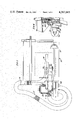
- FIG. 2 is a side elevational view of the table saw and sawdust collection system shown in FIG. 1;
- FIG. 3 is a fragmentary elevational view of the rear side of table saw with parts shown in section and is taken along line 3--3 of FIG. 2;
- FIG. 4 is a fragmentary cross-sectional view taken along line 4--4 of FIG. 3;
- FIG. 5 is a fragmentary elevational view of the front side of the saw base and is taken along line 5--5 of FIG. 2;
- FIG. 6 is a cross-sectional view taken along line 6--6 of FIG. 5;
- FIG. 7 is an elevational view of the swinging baffle plate shown alone
- FIG. 8 is an enlarged elevational view of the driving motor and attached centrifugal blower with parts shown in section and is taken along line 8--8 of FIG. 2;
- FIG. 9 is an elevational view of the centrifugal blower and is taken along line 9--9 of FIG. 8;
- FIG. 10 is an elevational view of one half of the blower casing showing the impeller therein and is taken along line 10--10 of FIG. 8;
- FIG. 11 is a fragmentary elevational view of the blower mounting plate and is taken along line 11--11 of FIG. 8;
- FIG. 12 is an enlarged cross-sectional view taken along line 12--12 of FIG. 11.
- FIG. 13 is a fragmentary cross-sectional view showing the method of attaching the two halves of the blower casing and is taken along line 13--13 of FIG. 9;
- FIG. 14 is an enlarged fragmentary cross-sectional view of the blower inlet collars and is taken along line 14--14 of FIG. 9;
- FIG. 15 is an elevational view of the connected half of the blower casing shown in FIG. 10 with the impeller removed.
- FIG. 16 is a cross-sectional view of the blower taken along line 16--16 of FIG. 9;
- FIG. 17 is a cross-sectional plan view taken along line 17--17 of FIG. 3;
- FIG. 18 is an enlarged fragmentary cross section taken along line 18--18 of FIG. 17;
- FIG. 19 is a further enlarged fragmentary cross section taken along line 19--19 of FIG. 17.
- FIGS. 1 to 5 of the drawings the elements of the sawdust collection system are shown assembled on a current commercially available belt driven table saw generally indicated at 10.
- the table saw has a worktable 12, a base 14, rectangular in plan, forms a casing enclosing saw tilting and elevating mechanism and a leg set 16 including a skirt 17 suitably attached to the bottom of the base.
- the bottom of base 14 is open and a collector bag 18 of suitable material closing the open bottom is detachably connected at its open end to the skirt 17 by elongated vertically extending clips 20 attached to the skirt on opposite sides of the base by bolts 21, see FIGS. 17, 18 and 19.
- the open end of the collector bag 18 is hemmed at 19 and rods 22 are inserted in the hem through cutouts 23 therein.
- End portions of rods 22 are formed at 90 degrees and the rods are arranged in the hem so as to hold the open end thereof in a generally rectangular shape with a pair of hem cutouts 23 on opposite sides thereof. Cross-stitching closes the hem at points 25 thereby to maintain the rods in proper position.
- the elongated vertically arranged clips 20 are attached at their upper ends to the inner surface of skirt 17 by the bolts 21 and have substantially the same spacing as hem cutouts 23. Clips 20 are formed so as to provide a rod receiving notch 27 immediately below their point of attachment. Downwardly from notch 27 the clips 20 are formed so as to flare outwardly from the inner surface of skirt 17 thereby to provide easy entry of rods 22 into notches 27.
- the open end is positioned so that cutouts 23 are aligned with clips 20.
- the bag is then moved upward with the flared lower portions of the clips passing through cutouts 23 and over those portions of the rods 22 extending across the cutouts. Further upward movement enters those rod portions into notches 27 whereby the bag is resiliently retained with the lower flared ends of clips 20 extending inside the bag.
- the bag 18 may be attached directly to the walls of base 14 in this manner instead of to the skirt 17. Also the bag may be attached in this manner to the walls defining any rectangular port for collecting waste material.
- the rear side of base 14 is also substantially open and the driving motor 24 is mounted outboard of the rear side of the base on a lower portion 26 of a swinging member 28 by rods 29 of an adjustable bracket 30 and by a motor mounting bracket 32 connected to adjustable bracket 30 by bolts 31, see FIG. 4. Hub portions 51 of the motor casing are cradled in turned up end portions 33 of mounting bracket 32 and are attached thereto by conventional clamps 35, see FIGS. 8, 11 and 12.
- the member 28 swings on trunnions at its upper end (not shown) and is fixed in angular position by suitable clamping means.
- a support bracket 36 supporting a hinged saw guard 38 is also attached to the swinging member 28 by screws 40 and a shaft 42 on which a driven belt pulley 44 and circular saw blade 46 are mounted is journalled in swinging member 28.
- the driving motor, pulleys, belt, saw blade and saw guard all swing with member 28 in attaining bevel positions of the saw blade.
- a centrifugal blower generally indicated at 48 is attached to one of the turned up end portions 33 of the motor mounting bracket 32 by a mounting plate 50 and a bar 52 which are connected by screws 54, see FIGS. 8, 11 and 12.
- the bar 52 bears against the inside of turned up portion 33 and the mounting plate 50 bears against a hub portion 51 of the motor casing and in spaced relationship with the outside of portion 33.
- the mounting plate 50 is also connected to the hub portion 51 of the motor casing via a special mounting clamp 56.
- Clamp 56 differs from conventional clamps 35 only in that it has a vertically elongated portion 57 to which a punched out and formed tab portion 59 of the mounting plate 50 is attached by a bolt 58, see FIGS. 11 and 12.
- the blower 48 has a casing formed of two halves 60 and 62 having front and rear walls 65 and 67 respectively and each having meeting flanges 64 and overlapping portions 66.
- the halves 60 and 62 are joined by clips 68, see FIG. 13.
- the casing half 60 has an integral skirt 70 projecting from its closed end which bears against and is connected to mounting plate 50 by screws 72.
- a V-belt drive pulley 74 is keyed to the motor output shaft 76 and positioned axially thereon intermediately of the wall 67 of blower casing half 60 and the mounting plate 50.
- the skirt 70 see FIG. 15, is shaped to form a guard for pulley 74 and drive belt 71.
- a circular impeller 78 within the blower casing has a hub portion connected to the drive pulley 74 by screws 80 entered into tapped holes 81 in the pulley 74, see FIGS. 8, 10 and 15.
- the blower casing has volute form with a flanged outlet 82 and a pair of elliptical, axial inlets 84 in the half 62 thereof.
- a fine sawdust collector bag 83 is suitably attached to the outlet 82 as by a drawstring.
- the inlets 84 are surrounded by elliptical projecting flanges or collars 86 for attachment thereon of one end of flexible conduits 91 and 93.
- the opposite end of conduit 91 is connected to a portion 90 integral with the hinged saw guard 38.
- the circular impeller 78 has a plurality of blades 79 angularly spaced about its axis of rotation which extend axially substantially between the casing walls 65 and 67 of the blower casing. Inner portions of the front edges of blades 79 adjacent the casing wall 65 are cut back as indicated at 75 to provide ample clearance to permit passage through the blower of any large pieces of the material being sawed which may enter the blower through inlets 84.
- baffle plate 92 shown alone in FIG. 7 is attached to the swinging member 28 by screws 40 and is positioned between the member 28 and the saw guard mounting bracket 36, see FIGS. 2 and 4.
- Baffle plate 92 has a cutout 94 therein shaped to slip over a lower projecting portion 26 of the member 28, a vertically elongated cutout 96 therein for passage of the saw driving belt 71 and an elliptical cutout 98 therein which receives the other end portion of flexible conduit 93.
- a sheet of thick, easily compressible foam rubber-like material 100 see FIG. 3.
- the arcuate slot 102 in the front sidewall of the saw base see FIGS. 5 and 6, which is conventionally provided in the front wall of base 14 to permit swinging of the saw elevating screw 104 when the saw blade is tilted, is closed with a strip of easily compressible foam rubber-like material 103 attached to the sidewall by clips 106.
- Other openings such as between the saw base and table are preferably sealed with strips of foam rubber-like material.
- the flexible conduits 91 and 93 are preferably round and corrugated and constructed of a relatively soft rubber-like material so as to flex easily without undue distortion as the front end of hinged saw guard 38 is raised or the baffle plate 92 is swung to the left when adjusting the saw blade to a bevel position.
- the opening 98 in the baffle plate 92, the inlets 84 and the collars 86 surrounding them in the blower housing are elliptical with relatively large major diameters and relatively small minor diameters so that to enter the opening 98 or to be slipped over the collars 86 the round rubber-like conduits are substantially distorted which retains them in connected position.
- the collars 86 and the connecting portion 90 of the saw blade guard 38 are provided with conduit retention protrusions 108 and 110 respectively. Referring to FIG. 1, the conduit 91 is supported in an elevated position above the worktable on a bracket 112.
- centrifugal blower 48 and the diameters of flexible conduits 91 and 93 are such as to cause a relatively large volume of air to flow through the saw guard and base at a relatively slow rate so as to collect virtually all of the fine sawdust particles likely to become airborne without withdrawing any appreciable amount of larger, heavier particles which are directed or fall into collector bag 18 by gravity.
Abstract
Description
Claims (14)
Priority Applications (2)
| Application Number | Priority Date | Filing Date | Title |
|---|---|---|---|
| US06/217,950 US4367665A (en) | 1980-12-19 | 1980-12-19 | Sawdust collection system |
| US06/421,435 US4489909A (en) | 1980-12-19 | 1982-09-22 | Sawdust collector bag for a table saw |
Applications Claiming Priority (1)
| Application Number | Priority Date | Filing Date | Title |
|---|---|---|---|
| US06/217,950 US4367665A (en) | 1980-12-19 | 1980-12-19 | Sawdust collection system |
Related Child Applications (1)
| Application Number | Title | Priority Date | Filing Date |
|---|---|---|---|
| US06/421,435 Division US4489909A (en) | 1980-12-19 | 1982-09-22 | Sawdust collector bag for a table saw |
Publications (1)
| Publication Number | Publication Date |
|---|---|
| US4367665A true US4367665A (en) | 1983-01-11 |
Family
ID=22813144
Family Applications (1)
| Application Number | Title | Priority Date | Filing Date |
|---|---|---|---|
| US06/217,950 Expired - Lifetime US4367665A (en) | 1980-12-19 | 1980-12-19 | Sawdust collection system |
Country Status (1)
| Country | Link |
|---|---|
| US (1) | US4367665A (en) |
Cited By (80)
| Publication number | Priority date | Publication date | Assignee | Title |
|---|---|---|---|---|
| US4517869A (en) * | 1980-10-18 | 1985-05-21 | Robert Bosch Gmbh | Saw table for a compass saw |
| US4704930A (en) * | 1984-05-03 | 1987-11-10 | Jagenberg Ag | Method and apparatus for removing edge strips from material webs of paper, cardboard or the like |
| WO1989010235A1 (en) * | 1988-04-29 | 1989-11-02 | Hans Zengerer | Device for cutting stone |
| US5158001A (en) * | 1991-08-09 | 1992-10-27 | Skil Corporation | Power table tool assemblies with dust collection system |
| AT397222B (en) * | 1992-05-20 | 1994-02-25 | Schelling & Co | Under floor sawing machine |
| US5307718A (en) * | 1992-10-29 | 1994-05-03 | The United States Of America As Represented By The United States Department Of Energy | Apparatus and process for removing a predetermined portion of reflective material from mirror |
| DE29603771U1 (en) * | 1996-03-01 | 1997-07-03 | Kober Ag | Suction device |
| US5782153A (en) * | 1995-06-08 | 1998-07-21 | Makita Corporation | Desk-top circular saw including chip discharging means |
| US5819619A (en) * | 1991-10-09 | 1998-10-13 | Black & Decker Inc. | Dust collection system for compound miter saw |
| US5884544A (en) * | 1997-11-18 | 1999-03-23 | Emerson Electric Co. | Scroll saw vacuum attachment assembly |
| US5931072A (en) * | 1996-07-23 | 1999-08-03 | Makita Corporation | Circular saw with an improved dust collector |
| US5953973A (en) * | 1997-11-04 | 1999-09-21 | Clifford; Allen E. | Exhaust-driven sawdust venting attachment for a sawmill |
| WO2000013844A1 (en) * | 1998-09-09 | 2000-03-16 | The Gleason Works | Apparatus for chip removal |
| US6047693A (en) * | 1997-06-30 | 2000-04-11 | Kioritz Corporation | Dust collector-equipped power cutter |
| US6244147B1 (en) * | 1998-09-02 | 2001-06-12 | The E. H. Wachs Company | Weld sample cutter |
| US6427570B1 (en) | 1991-10-09 | 2002-08-06 | Black & Decker Inc. | Dust collection system for compound miter saw |
| US6470778B1 (en) | 1998-05-20 | 2002-10-29 | Black & Decker Inc. | Dust collector for a power tool |
| US6546835B2 (en) * | 2001-01-25 | 2003-04-15 | Tian Wang Wang | Saw blade adjusting device for table saw |
| US6601621B2 (en) * | 2001-04-18 | 2003-08-05 | Black & Decker Inc. | Portable Power Planer |
| US20030209118A1 (en) * | 2001-07-23 | 2003-11-13 | Roberts David C. | Method of positioning a window covering ina sizing mechanism |
| US20030209120A1 (en) * | 2002-05-10 | 2003-11-13 | Juei-Seng Liao | Scroll sawing machine with a sawdust collecting mechanism |
| US20040069104A1 (en) * | 2001-07-23 | 2004-04-15 | Caputo Thomas A. | Modular blind cutting center |
| WO2004045814A1 (en) * | 2002-11-18 | 2004-06-03 | Young-Suok Lee | Apparatus for cutting lumber |
| US20040173066A1 (en) * | 2003-03-03 | 2004-09-09 | Joshua Abdollahzadeh | Blind cutting center with multi-speed saw |
| US20040173076A1 (en) * | 2003-03-03 | 2004-09-09 | Joseph Potts | Automatically configurable blind cutting center |
| US20040173079A1 (en) * | 2003-03-03 | 2004-09-09 | Caputo Thomas A. | Adjustable blind cutting device |
| US20040173075A1 (en) * | 2003-03-03 | 2004-09-09 | Schwartz David A. | Remotely connected blind cutting center |
| US20040173077A1 (en) * | 2003-03-03 | 2004-09-09 | Abdollahzadeh Joshua A. | Blind cutting center with detachable vacuum bag |
| US6796208B1 (en) | 1999-02-19 | 2004-09-28 | Matthew Roy Jorgensen | Sawdust collection hood for table saw |
| US20040187449A1 (en) * | 2003-03-27 | 2004-09-30 | Oneida Air Systems, Inc. | Dust collection system |
| US20040206220A1 (en) * | 2003-03-31 | 2004-10-21 | Keenan Richard Francis | Sawdust collector for table saws |
| EP1484127A2 (en) * | 2003-06-05 | 2004-12-08 | Techtronic Industries Co., Ltd. | Motor driven wood working tool with vacuum feature |
| US6899005B1 (en) | 1991-10-09 | 2005-05-31 | Black & Decker Inc. | Adjustable fence for compound miter saw |
| US6899004B1 (en) * | 1998-08-14 | 2005-05-31 | Delta International Machinery Corp. | Sawing apparatus and saw fence system |
| US7178439B2 (en) | 2003-03-03 | 2007-02-20 | Newell Window Furnishings, Inc. | Blind cutting center |
| US20070074613A1 (en) * | 2005-10-04 | 2007-04-05 | Ben Yu | Worktable having adjustable shield |
| US20070239551A1 (en) * | 2006-03-30 | 2007-10-11 | Zeller Michelle G | Method and apparatus for a product ordering system |
| CN100446905C (en) * | 2005-07-14 | 2008-12-31 | 株式会社牧田 | Dust collector of fixed type cutting machine |
| US20090031876A1 (en) * | 2007-07-31 | 2009-02-05 | Newell Window Furnishings, Inc. | Window covering sizing method and apparatus |
| USRE40697E1 (en) * | 2002-06-12 | 2009-04-07 | Sabic Innovative Plastics Ip B.V. | Method for making an aromatic polycarbonate |
| US20090178593A1 (en) * | 2008-01-14 | 2009-07-16 | Ben Yu | Work table having adjustable hose support |
| US20100037740A1 (en) * | 2008-08-18 | 2010-02-18 | Kun-Yen Lin | Dust Control Hood Assembly for a Cutting Machine |
| US20100058911A1 (en) * | 2008-09-11 | 2010-03-11 | Jay Aaron Goddard | Blade Guard for Power Tool Having an Evacuation System |
| US20100089497A1 (en) * | 2008-01-12 | 2010-04-15 | Keenan Richard F | Router Dust Collection Assembly |
| US20100269654A1 (en) * | 2009-04-28 | 2010-10-28 | Needel Gregory E | Dust Collection System for a Power Tool |
| US20100285729A1 (en) * | 2009-05-08 | 2010-11-11 | Michael Loveless | Angle grinder dust shroud with unitary adjustable mounting collar |
| US20100307308A1 (en) * | 2009-06-09 | 2010-12-09 | Butler David J | Blade enclosure for a table saw |
| US20110021121A1 (en) * | 2009-07-21 | 2011-01-27 | Spencer Loveless | Angle grinder dust shroud with slideable access hatch |
| US20110056348A1 (en) * | 2007-07-31 | 2011-03-10 | Newell Window Furnishings, Inc. | Window covering sizing method and apparatus |
| US20110056345A1 (en) * | 2007-07-31 | 2011-03-10 | Newell Window Furnishings, Inc. | Window covering sizing method and apparatus |
| US20110056353A1 (en) * | 2007-07-31 | 2011-03-10 | Newell Window Furnishings, Inc. | Window covering sizing method and apparatus |
| US20110061505A1 (en) * | 2007-07-31 | 2011-03-17 | Newell Window Furnishings, Inc. | Window covering sizing method and apparatus |
| US20110192262A1 (en) * | 2009-08-18 | 2011-08-11 | Spencer Loveless | Cutoff saw and stand with integrated dust filtration system |
| US20120036972A1 (en) * | 2010-08-13 | 2012-02-16 | Robert Bosch Gmbh | Dust management system in a table saw |
| US20130098217A1 (en) * | 2006-04-21 | 2013-04-25 | Robert P. Welsh | Table Saw |
| US8479925B2 (en) | 2010-07-19 | 2013-07-09 | Newell Window Furnishings, Inc. | Display system |
| US8726774B1 (en) | 2012-03-26 | 2014-05-20 | David Kellum | Miter saw dust collector apparatus |
| US20140157965A1 (en) * | 2011-12-30 | 2014-06-12 | John Simon | Machine for Cutting of Masonry, Wood and Other Materials |
| US20150082958A1 (en) * | 2013-09-25 | 2015-03-26 | Zhen Feng | Woodworking Table Saw with Vacuuming Function |
| US9038275B2 (en) | 2011-09-07 | 2015-05-26 | Dustless Depot, Llc | Reciprocating saw dust shroud |
| US9266639B2 (en) | 2010-07-19 | 2016-02-23 | Newell Window Furnishings, Inc. | Blind packaging and methods of cutting window coverings |
| US20160088990A1 (en) * | 2014-09-28 | 2016-03-31 | Robert Charles Anderson | Loading Apparatus for Dust Collection Containers |
| US9511429B2 (en) | 2013-03-15 | 2016-12-06 | Robert BoschTool Corporation | Blade drop for power device and method of manufacturing thereof |
| US9517516B2 (en) | 2013-03-14 | 2016-12-13 | Robert Bosch Tool Corporation | Blade drop power tool with dust management |
| CN107107293A (en) * | 2014-12-31 | 2017-08-29 | 3M创新有限公司 | Dust arrester |
| US9878380B2 (en) | 1999-10-01 | 2018-01-30 | Sawstop Holding Llc | Table saw throat plates and table saws including the same |
| USD816453S1 (en) | 2016-09-15 | 2018-05-01 | Dustless Depot, Llc | Circular saw dust shroud |
| US10022811B2 (en) | 2009-07-31 | 2018-07-17 | Sawstop Holding Llc | Dust collection system for a table saw |
| CN109291174A (en) * | 2018-09-25 | 2019-02-01 | 王鸳 | A kind of Furniture manufacturing dedusting collection sawdust box |
| US10293421B2 (en) | 2016-09-15 | 2019-05-21 | Dustless Depot, Llc | Circular saw dust collection shroud |
| US20190240750A1 (en) * | 2018-02-08 | 2019-08-08 | Yongkang Congzhen Tools Co.,Ltd | Stage dedusting shield for dust-free table saw |
| CN111136305A (en) * | 2020-01-22 | 2020-05-12 | 浙江舜特机械设备有限公司 | Heat exchanger tube sheet processingequipment |
| US20200198316A1 (en) * | 2017-08-30 | 2020-06-25 | Commissariat A L'energie Atomique Et Aux Energies Alternatives | Method for disassembling a photovoltaic module and associated installation |
| USD908149S1 (en) | 2018-10-23 | 2021-01-19 | Dustless Depot Llc | Angle grinder dust shroud with variable position slots for mounting brackets |
| US20210170511A1 (en) * | 2015-08-28 | 2021-06-10 | Mark J. DRAGAN | Collecting sawdust and other debris from power saws |
| US11123839B2 (en) | 2018-10-23 | 2021-09-21 | Dustless Depot Llc | Grinder dust shroud with input shaft gasket and adjustable mounting mechanism |
| US11273505B2 (en) | 2019-03-27 | 2022-03-15 | Dustless Depot, Llc | Circular saw dust collection shroud |
| CN114800719A (en) * | 2022-05-16 | 2022-07-29 | 南京林业大学 | Furniture production equipment with automatic wood chip collecting function |
| WO2023145934A1 (en) * | 2022-01-31 | 2023-08-03 | 株式会社牧野フライス製作所 | Machine tool |
| WO2024068296A1 (en) * | 2022-09-28 | 2024-04-04 | Festool Gmbh | Circular saw |
Citations (12)
| Publication number | Priority date | Publication date | Assignee | Title |
|---|---|---|---|---|
| US1496035A (en) * | 1921-11-04 | 1924-06-03 | Crescent Machine Company | Combined guard and blower |
| DE501042C (en) * | 1928-06-30 | 1930-06-27 | Old Colony Envelope Company | Machine for processing or decorating the edges of paper or similar materials |
| US2044481A (en) * | 1934-12-08 | 1936-06-16 | Western Electric Co | Material working machine |
| US2236232A (en) * | 1938-09-03 | 1941-03-25 | Western Electric Co | Exhausting apparatus |
| US2711061A (en) * | 1954-07-29 | 1955-06-21 | Gallagher Kaiser Corp | Dust collector |
| US3007501A (en) * | 1959-06-11 | 1961-11-07 | Handman Inc | Combination woodworking machine |
| US3267974A (en) * | 1964-07-16 | 1966-08-23 | Black & Decker Mfg Co | Saw dust blower for portable power-driven saw |
| US3322169A (en) * | 1964-08-03 | 1967-05-30 | Floyd T Hilliard | Sawdust collecting means for radial saws |
| US3401724A (en) * | 1965-10-12 | 1968-09-17 | Lloyd D. Kreitz | Dust collector |
| US3669163A (en) * | 1970-04-15 | 1972-06-13 | Herbert R Crane | Band saw with sawdust ejection means |
| US4201256A (en) * | 1979-01-10 | 1980-05-06 | Andrew Truhan | Sawdust collector |
| US4270427A (en) * | 1980-02-04 | 1981-06-02 | Black & Decker Inc. | Bevel angle setting means for a power tool apparatus |
-
1980
- 1980-12-19 US US06/217,950 patent/US4367665A/en not_active Expired - Lifetime
Patent Citations (12)
| Publication number | Priority date | Publication date | Assignee | Title |
|---|---|---|---|---|
| US1496035A (en) * | 1921-11-04 | 1924-06-03 | Crescent Machine Company | Combined guard and blower |
| DE501042C (en) * | 1928-06-30 | 1930-06-27 | Old Colony Envelope Company | Machine for processing or decorating the edges of paper or similar materials |
| US2044481A (en) * | 1934-12-08 | 1936-06-16 | Western Electric Co | Material working machine |
| US2236232A (en) * | 1938-09-03 | 1941-03-25 | Western Electric Co | Exhausting apparatus |
| US2711061A (en) * | 1954-07-29 | 1955-06-21 | Gallagher Kaiser Corp | Dust collector |
| US3007501A (en) * | 1959-06-11 | 1961-11-07 | Handman Inc | Combination woodworking machine |
| US3267974A (en) * | 1964-07-16 | 1966-08-23 | Black & Decker Mfg Co | Saw dust blower for portable power-driven saw |
| US3322169A (en) * | 1964-08-03 | 1967-05-30 | Floyd T Hilliard | Sawdust collecting means for radial saws |
| US3401724A (en) * | 1965-10-12 | 1968-09-17 | Lloyd D. Kreitz | Dust collector |
| US3669163A (en) * | 1970-04-15 | 1972-06-13 | Herbert R Crane | Band saw with sawdust ejection means |
| US4201256A (en) * | 1979-01-10 | 1980-05-06 | Andrew Truhan | Sawdust collector |
| US4270427A (en) * | 1980-02-04 | 1981-06-02 | Black & Decker Inc. | Bevel angle setting means for a power tool apparatus |
Cited By (141)
| Publication number | Priority date | Publication date | Assignee | Title |
|---|---|---|---|---|
| US4517869A (en) * | 1980-10-18 | 1985-05-21 | Robert Bosch Gmbh | Saw table for a compass saw |
| US4704930A (en) * | 1984-05-03 | 1987-11-10 | Jagenberg Ag | Method and apparatus for removing edge strips from material webs of paper, cardboard or the like |
| WO1989010235A1 (en) * | 1988-04-29 | 1989-11-02 | Hans Zengerer | Device for cutting stone |
| AU647301B2 (en) * | 1991-08-09 | 1994-03-17 | Skil Corporation | Power table tool assemblies with dust collection system |
| US5158001A (en) * | 1991-08-09 | 1992-10-27 | Skil Corporation | Power table tool assemblies with dust collection system |
| US6431040B1 (en) | 1991-10-09 | 2002-08-13 | Black & Decker Inc. | Dust collection system for compound miter saw |
| US6427570B1 (en) | 1991-10-09 | 2002-08-06 | Black & Decker Inc. | Dust collection system for compound miter saw |
| US5819619A (en) * | 1991-10-09 | 1998-10-13 | Black & Decker Inc. | Dust collection system for compound miter saw |
| US6899005B1 (en) | 1991-10-09 | 2005-05-31 | Black & Decker Inc. | Adjustable fence for compound miter saw |
| AT397222B (en) * | 1992-05-20 | 1994-02-25 | Schelling & Co | Under floor sawing machine |
| US5307718A (en) * | 1992-10-29 | 1994-05-03 | The United States Of America As Represented By The United States Department Of Energy | Apparatus and process for removing a predetermined portion of reflective material from mirror |
| US5782153A (en) * | 1995-06-08 | 1998-07-21 | Makita Corporation | Desk-top circular saw including chip discharging means |
| DE29603771U1 (en) * | 1996-03-01 | 1997-07-03 | Kober Ag | Suction device |
| US5931072A (en) * | 1996-07-23 | 1999-08-03 | Makita Corporation | Circular saw with an improved dust collector |
| US6047693A (en) * | 1997-06-30 | 2000-04-11 | Kioritz Corporation | Dust collector-equipped power cutter |
| US5953973A (en) * | 1997-11-04 | 1999-09-21 | Clifford; Allen E. | Exhaust-driven sawdust venting attachment for a sawmill |
| US5884544A (en) * | 1997-11-18 | 1999-03-23 | Emerson Electric Co. | Scroll saw vacuum attachment assembly |
| US6470778B1 (en) | 1998-05-20 | 2002-10-29 | Black & Decker Inc. | Dust collector for a power tool |
| US6899004B1 (en) * | 1998-08-14 | 2005-05-31 | Delta International Machinery Corp. | Sawing apparatus and saw fence system |
| US7594459B2 (en) | 1998-08-14 | 2009-09-29 | Delta International Machinery Corp. | Sawing apparatus with debris collection system and accessory shelf |
| US6244147B1 (en) * | 1998-09-02 | 2001-06-12 | The E. H. Wachs Company | Weld sample cutter |
| US6206621B1 (en) | 1998-09-09 | 2001-03-27 | The Gleason Works | Apparatus for chip removal |
| WO2000013844A1 (en) * | 1998-09-09 | 2000-03-16 | The Gleason Works | Apparatus for chip removal |
| US6796208B1 (en) | 1999-02-19 | 2004-09-28 | Matthew Roy Jorgensen | Sawdust collection hood for table saw |
| US7000515B2 (en) | 1999-02-19 | 2006-02-21 | Jorgensen Matthew R | Sawdust collection hood for table saw |
| US9878380B2 (en) | 1999-10-01 | 2018-01-30 | Sawstop Holding Llc | Table saw throat plates and table saws including the same |
| US6546835B2 (en) * | 2001-01-25 | 2003-04-15 | Tian Wang Wang | Saw blade adjusting device for table saw |
| US20060090816A1 (en) * | 2001-04-18 | 2006-05-04 | Barry Wixey | Portable power planer with height scale |
| US20040144446A1 (en) * | 2001-04-18 | 2004-07-29 | Barry Wixey | Portable power planer |
| US7428917B2 (en) | 2001-04-18 | 2008-09-30 | Black & Decker Inc. | Portable power planer with height scale |
| US6918419B2 (en) | 2001-04-18 | 2005-07-19 | Black & Decker Inc. | Portable power planer |
| US6708744B2 (en) | 2001-04-18 | 2004-03-23 | Black & Decker Inc. | Portable power planer |
| US6601621B2 (en) * | 2001-04-18 | 2003-08-05 | Black & Decker Inc. | Portable Power Planer |
| US6886615B2 (en) | 2001-04-18 | 2005-05-03 | Black & Decker Inc. | Portable power planer |
| US20040250889A1 (en) * | 2001-04-18 | 2004-12-16 | Barry Wixey | Portable power planer |
| US20050076972A1 (en) * | 2001-04-18 | 2005-04-14 | Barry Wixey | Multi-piece machine tool base |
| US20030209118A1 (en) * | 2001-07-23 | 2003-11-13 | Roberts David C. | Method of positioning a window covering ina sizing mechanism |
| US7100485B2 (en) * | 2001-07-23 | 2006-09-05 | Newell Window Furnishings, Inc. | Blind and shade cutting center |
| US7069832B2 (en) | 2001-07-23 | 2006-07-04 | Newell Window Furnishings, Inc. | Blind and shade cutting center with movable locator |
| US7681480B2 (en) | 2001-07-23 | 2010-03-23 | Newell Window Furnishings, Inc. | Blind and shade cutting center for cutting two different window covering products |
| US20040069104A1 (en) * | 2001-07-23 | 2004-04-15 | Caputo Thomas A. | Modular blind cutting center |
| US7040205B2 (en) | 2001-07-23 | 2006-05-09 | Newell Window Furnishings, Inc | Blind and shade cutting center with movable cutting station |
| US8499670B2 (en) | 2001-07-23 | 2013-08-06 | Newell Window Furnishings, Inc. | Modular blind cutting center |
| US7069833B2 (en) | 2001-07-23 | 2006-07-04 | Newell Window Furnishings, Inc. | Moveable blind and shade cutting center |
| US8161857B2 (en) | 2001-07-23 | 2012-04-24 | Newell Window Furnishings, Inc. | Blind and shade cutting center for cutting two different window covering products |
| US20100107839A1 (en) * | 2001-07-23 | 2010-05-06 | Newell Window Furnishings, Inc. | Blind and shade cutting center for cutting two different window covering products |
| US8286538B2 (en) | 2001-07-23 | 2012-10-16 | Newell Window Furnishings, Inc. | Blind and shade cutting center for cutting two different window covering products |
| US7104175B2 (en) | 2001-07-23 | 2006-09-12 | Newell Window Furnishings, Inc. | Blind and shade cutting center with center locating system |
| US7007576B2 (en) | 2001-07-23 | 2006-03-07 | Newell Window Furnishings, Inc. | Method of positioning a window covering in a sizing mechanism |
| US6722239B2 (en) * | 2002-05-10 | 2004-04-20 | Juei-Seng Liao | Scroll sawing machine with a sawdust collecting mechanism |
| US20030209120A1 (en) * | 2002-05-10 | 2003-11-13 | Juei-Seng Liao | Scroll sawing machine with a sawdust collecting mechanism |
| USRE40697E1 (en) * | 2002-06-12 | 2009-04-07 | Sabic Innovative Plastics Ip B.V. | Method for making an aromatic polycarbonate |
| WO2004045814A1 (en) * | 2002-11-18 | 2004-06-03 | Young-Suok Lee | Apparatus for cutting lumber |
| US20040173076A1 (en) * | 2003-03-03 | 2004-09-09 | Joseph Potts | Automatically configurable blind cutting center |
| US20040173075A1 (en) * | 2003-03-03 | 2004-09-09 | Schwartz David A. | Remotely connected blind cutting center |
| US7036412B2 (en) | 2003-03-03 | 2006-05-02 | Newell Window Furnishings, Inc. | Blind cutting center with detachable vacuum bag |
| US20040173066A1 (en) * | 2003-03-03 | 2004-09-09 | Joshua Abdollahzadeh | Blind cutting center with multi-speed saw |
| US7178439B2 (en) | 2003-03-03 | 2007-02-20 | Newell Window Furnishings, Inc. | Blind cutting center |
| US6973364B2 (en) | 2003-03-03 | 2005-12-06 | Schwartz David A | Remotely connected blind cutting center |
| US7810418B2 (en) | 2003-03-03 | 2010-10-12 | Newell Window Furnishings, Inc. | Automatically configurable blind cutting center |
| US20040173079A1 (en) * | 2003-03-03 | 2004-09-09 | Caputo Thomas A. | Adjustable blind cutting device |
| US10792739B2 (en) | 2003-03-03 | 2020-10-06 | Hunter Douglas Industries Switzerland Gmbh | Automatically configurable blind cutting center |
| US7059230B2 (en) | 2003-03-03 | 2006-06-13 | Caputo Thomas A | Adjustable blind cutting device |
| US20110088524A1 (en) * | 2003-03-03 | 2011-04-21 | Newell Window Furnishings, Inc. | Automatically Configurable Blind Cutting Center |
| US20040173077A1 (en) * | 2003-03-03 | 2004-09-09 | Abdollahzadeh Joshua A. | Blind cutting center with detachable vacuum bag |
| US20040187449A1 (en) * | 2003-03-27 | 2004-09-30 | Oneida Air Systems, Inc. | Dust collection system |
| USRE40048E1 (en) * | 2003-03-27 | 2008-02-12 | Oneida Air Systems, Inc. | Dust collection system |
| US6833016B2 (en) * | 2003-03-27 | 2004-12-21 | Oneida Air Systems, Inc | Dust collection system |
| US7216572B2 (en) | 2003-03-31 | 2007-05-15 | Richard Francis Keenan | Sawdust collector for table saws |
| US20040206220A1 (en) * | 2003-03-31 | 2004-10-21 | Keenan Richard Francis | Sawdust collector for table saws |
| EP1484127A2 (en) * | 2003-06-05 | 2004-12-08 | Techtronic Industries Co., Ltd. | Motor driven wood working tool with vacuum feature |
| EP1484127A3 (en) * | 2003-06-05 | 2004-12-29 | Techtronic Industries Co., Ltd. | Motor driven wood working tool with vacuum feature |
| CN100446905C (en) * | 2005-07-14 | 2008-12-31 | 株式会社牧田 | Dust collector of fixed type cutting machine |
| US20070074613A1 (en) * | 2005-10-04 | 2007-04-05 | Ben Yu | Worktable having adjustable shield |
| US20070239551A1 (en) * | 2006-03-30 | 2007-10-11 | Zeller Michelle G | Method and apparatus for a product ordering system |
| US20130098217A1 (en) * | 2006-04-21 | 2013-04-25 | Robert P. Welsh | Table Saw |
| US9776260B2 (en) * | 2006-04-21 | 2017-10-03 | Black & Decker Inc. | Table saw |
| US20110056345A1 (en) * | 2007-07-31 | 2011-03-10 | Newell Window Furnishings, Inc. | Window covering sizing method and apparatus |
| US20110061505A1 (en) * | 2007-07-31 | 2011-03-17 | Newell Window Furnishings, Inc. | Window covering sizing method and apparatus |
| US8839701B2 (en) | 2007-07-31 | 2014-09-23 | Newell Window Furnishings, Inc. | Window covering sizing method and apparatus |
| US20110056348A1 (en) * | 2007-07-31 | 2011-03-10 | Newell Window Furnishings, Inc. | Window covering sizing method and apparatus |
| US8322260B2 (en) | 2007-07-31 | 2012-12-04 | Newell Window Furnishings, Inc. | Window covering sizing method and apparatus |
| US20110056353A1 (en) * | 2007-07-31 | 2011-03-10 | Newell Window Furnishings, Inc. | Window covering sizing method and apparatus |
| US8631732B1 (en) | 2007-07-31 | 2014-01-21 | Newell Window Furnishings, Inc. | Window covering sizing method and apparatus |
| US9427813B2 (en) | 2007-07-31 | 2016-08-30 | Newell Window Furnishing, Inc. | Window covering sizing method and apparatus |
| US11872716B2 (en) | 2007-07-31 | 2024-01-16 | Hunter Douglas Industries Switzerland Gmbh | Window covering sizing method and apparatus |
| US7987754B2 (en) | 2007-07-31 | 2011-08-02 | Newell Window Furnishings, Inc. | Window covering sizing method and apparatus |
| US20090031876A1 (en) * | 2007-07-31 | 2009-02-05 | Newell Window Furnishings, Inc. | Window covering sizing method and apparatus |
| US9440368B2 (en) | 2007-07-31 | 2016-09-13 | Newell Window Furnishings, Inc. | Window covering sizing method and apparatus |
| US10786921B2 (en) | 2007-07-31 | 2020-09-29 | Hunter Douglas Industries Switzerland Gmbh | Window covering sizing method and apparatus |
| US8256333B2 (en) | 2007-07-31 | 2012-09-04 | Newell Window Furnishings, Inc. | Window covering sizing method and apparatus |
| US20100206144A1 (en) * | 2007-07-31 | 2010-08-19 | Newell Window Furnishings Inc. | Window covering sizing method and apparatus |
| US20100089497A1 (en) * | 2008-01-12 | 2010-04-15 | Keenan Richard F | Router Dust Collection Assembly |
| US7905260B2 (en) * | 2008-01-12 | 2011-03-15 | Richard Keenan | Router dust collection assembly |
| US20090178593A1 (en) * | 2008-01-14 | 2009-07-16 | Ben Yu | Work table having adjustable hose support |
| US7775143B2 (en) * | 2008-01-14 | 2010-08-17 | Ben Yu | Work table having adjustable hose support |
| US20100037740A1 (en) * | 2008-08-18 | 2010-02-18 | Kun-Yen Lin | Dust Control Hood Assembly for a Cutting Machine |
| US20100058911A1 (en) * | 2008-09-11 | 2010-03-11 | Jay Aaron Goddard | Blade Guard for Power Tool Having an Evacuation System |
| US20100269654A1 (en) * | 2009-04-28 | 2010-10-28 | Needel Gregory E | Dust Collection System for a Power Tool |
| US20100285729A1 (en) * | 2009-05-08 | 2010-11-11 | Michael Loveless | Angle grinder dust shroud with unitary adjustable mounting collar |
| US8702478B2 (en) | 2009-05-08 | 2014-04-22 | Michael Loveless | Angle grinder dust shroud with unitary adjustable mounting collar |
| US20100307308A1 (en) * | 2009-06-09 | 2010-12-09 | Butler David J | Blade enclosure for a table saw |
| US20110021121A1 (en) * | 2009-07-21 | 2011-01-27 | Spencer Loveless | Angle grinder dust shroud with slideable access hatch |
| US8523637B2 (en) | 2009-07-21 | 2013-09-03 | Dustless Depot, Llc | Angle grinder dust shroud with slideable access hatch |
| US10737338B2 (en) | 2009-07-31 | 2020-08-11 | Sawstop Holding Llc | Insert for a table saw |
| US10022811B2 (en) | 2009-07-31 | 2018-07-17 | Sawstop Holding Llc | Dust collection system for a table saw |
| US8561512B2 (en) * | 2009-08-18 | 2013-10-22 | Dustless Depot Llc | Cutoff saw and stand with integrated dust filtration system |
| US20110192262A1 (en) * | 2009-08-18 | 2011-08-11 | Spencer Loveless | Cutoff saw and stand with integrated dust filtration system |
| US9266639B2 (en) | 2010-07-19 | 2016-02-23 | Newell Window Furnishings, Inc. | Blind packaging and methods of cutting window coverings |
| US8479925B2 (en) | 2010-07-19 | 2013-07-09 | Newell Window Furnishings, Inc. | Display system |
| US11312566B2 (en) | 2010-07-19 | 2022-04-26 | Hunter Douglas Industries Switzerland Gmbh | Blind packaging and methods of cutting window coverings |
| US10450129B2 (en) | 2010-07-19 | 2019-10-22 | Levolor, Inc. | Blind packaging and methods of cutting window coverings |
| US20120036972A1 (en) * | 2010-08-13 | 2012-02-16 | Robert Bosch Gmbh | Dust management system in a table saw |
| US8752462B2 (en) * | 2010-08-13 | 2014-06-17 | Robert Bosch Gmbh | Dust management system in a table saw |
| US9038275B2 (en) | 2011-09-07 | 2015-05-26 | Dustless Depot, Llc | Reciprocating saw dust shroud |
| US9168665B2 (en) * | 2011-12-30 | 2015-10-27 | John Simon | Machine for cutting of masonry, wood and other materials |
| US20140157965A1 (en) * | 2011-12-30 | 2014-06-12 | John Simon | Machine for Cutting of Masonry, Wood and Other Materials |
| US8726774B1 (en) | 2012-03-26 | 2014-05-20 | David Kellum | Miter saw dust collector apparatus |
| US9517516B2 (en) | 2013-03-14 | 2016-12-13 | Robert Bosch Tool Corporation | Blade drop power tool with dust management |
| US9511429B2 (en) | 2013-03-15 | 2016-12-06 | Robert BoschTool Corporation | Blade drop for power device and method of manufacturing thereof |
| US9597816B2 (en) * | 2013-09-25 | 2017-03-21 | Zhen Feng | Woodworking table saw with vacuuming function |
| US20150082958A1 (en) * | 2013-09-25 | 2015-03-26 | Zhen Feng | Woodworking Table Saw with Vacuuming Function |
| US20160088990A1 (en) * | 2014-09-28 | 2016-03-31 | Robert Charles Anderson | Loading Apparatus for Dust Collection Containers |
| US9744538B2 (en) * | 2014-09-28 | 2017-08-29 | Robert C. Anderson | Loading apparatus for dust collection containers |
| CN107107293A (en) * | 2014-12-31 | 2017-08-29 | 3M创新有限公司 | Dust arrester |
| US20210170511A1 (en) * | 2015-08-28 | 2021-06-10 | Mark J. DRAGAN | Collecting sawdust and other debris from power saws |
| USD816453S1 (en) | 2016-09-15 | 2018-05-01 | Dustless Depot, Llc | Circular saw dust shroud |
| US10293421B2 (en) | 2016-09-15 | 2019-05-21 | Dustless Depot, Llc | Circular saw dust collection shroud |
| US20200198316A1 (en) * | 2017-08-30 | 2020-06-25 | Commissariat A L'energie Atomique Et Aux Energies Alternatives | Method for disassembling a photovoltaic module and associated installation |
| US10576561B2 (en) * | 2018-02-08 | 2020-03-03 | Yongkang Congzhen Tools Co., Ltd | Stage dedusting shield for dust-free table saw |
| US20190240750A1 (en) * | 2018-02-08 | 2019-08-08 | Yongkang Congzhen Tools Co.,Ltd | Stage dedusting shield for dust-free table saw |
| CN109291174A (en) * | 2018-09-25 | 2019-02-01 | 王鸳 | A kind of Furniture manufacturing dedusting collection sawdust box |
| USD908149S1 (en) | 2018-10-23 | 2021-01-19 | Dustless Depot Llc | Angle grinder dust shroud with variable position slots for mounting brackets |
| US11123839B2 (en) | 2018-10-23 | 2021-09-21 | Dustless Depot Llc | Grinder dust shroud with input shaft gasket and adjustable mounting mechanism |
| US11273505B2 (en) | 2019-03-27 | 2022-03-15 | Dustless Depot, Llc | Circular saw dust collection shroud |
| CN111136305B (en) * | 2020-01-22 | 2020-12-08 | 浙江舜特机械设备有限公司 | Heat exchanger tube sheet processingequipment |
| CN111136305A (en) * | 2020-01-22 | 2020-05-12 | 浙江舜特机械设备有限公司 | Heat exchanger tube sheet processingequipment |
| WO2023145934A1 (en) * | 2022-01-31 | 2023-08-03 | 株式会社牧野フライス製作所 | Machine tool |
| CN114800719A (en) * | 2022-05-16 | 2022-07-29 | 南京林业大学 | Furniture production equipment with automatic wood chip collecting function |
| CN114800719B (en) * | 2022-05-16 | 2022-12-20 | 南京林业大学 | Furniture production equipment with automatic wood chip collecting function |
| WO2024068296A1 (en) * | 2022-09-28 | 2024-04-04 | Festool Gmbh | Circular saw |
Similar Documents
| Publication | Publication Date | Title |
|---|---|---|
| US4367665A (en) | Sawdust collection system | |
| US4576072A (en) | Sawdust collection apparatus for a table saw | |
| EP1484127B1 (en) | Band saw with vacuum feature | |
| US4063478A (en) | Saw enclosure construction | |
| US3882598A (en) | Dust control cutting assembly for cutting sheet material | |
| US3401724A (en) | Dust collector | |
| US6293321B1 (en) | Wood planing machine with a sawdust-collecting mechanism | |
| US8726773B2 (en) | Table saw having airflow apparatus | |
| US3669163A (en) | Band saw with sawdust ejection means | |
| US4230005A (en) | Traveling circular saw | |
| US20070044609A1 (en) | Motor driven wood working tool with vacuum feature | |
| US2839102A (en) | Dust collecting attachments for power saws | |
| US2634560A (en) | Traveling waste collector | |
| US2733000A (en) | sparklin | |
| CA3067665C (en) | Centrifugal gas separator | |
| US2189021A (en) | Air conditioning apparatus | |
| US4061126A (en) | Ceramic tile cutting apparatus | |
| US3305163A (en) | Ventilator | |
| DE3460303D1 (en) | Device for cooling the electric drive motor for the disc blade of a slicing machine | |
| GB1036707A (en) | Improvements in and relating to a suction unit, particularly for cleaning apparatus | |
| US4683608A (en) | Alternate blower outlet for vacuum cleaner | |
| US2905266A (en) | Separators | |
| CN102441706B (en) | Mitre saw | |
| US3075322A (en) | Power operated knife sharpener | |
| US2413499A (en) | Unit dust collector |
Legal Events
| Date | Code | Title | Description |
|---|---|---|---|
| AS | Assignment |
Owner name: EMERSON ELECTRIC CO., 8000 WEST FLORISSANT AVE., P Free format text: ASSIGNMENT OF ASSIGNORS INTEREST.;ASSIGNORS:TERPSTRA, DANIEL A.;BRUNDAGE, RICHARD B.;REEL/FRAME:004040/0452 Effective date: 19810925 |
|
| STCF | Information on status: patent grant |
Free format text: PATENTED CASE |
|
| MAFP | Maintenance fee payment |
Free format text: PAYMENT OF MAINTENANCE FEE, 4TH YEAR, PL 96-517 (ORIGINAL EVENT CODE: M170); ENTITY STATUS OF PATENT OWNER: LARGE ENTITY Year of fee payment: 4 |
|
| MAFP | Maintenance fee payment |
Free format text: PAYMENT OF MAINTENANCE FEE, 8TH YEAR, PL 96-517 (ORIGINAL EVENT CODE: M171); ENTITY STATUS OF PATENT OWNER: LARGE ENTITY Year of fee payment: 8 |
|
| MAFP | Maintenance fee payment |
Free format text: PAYMENT OF MAINTENANCE FEE, 12TH YEAR, LARGE ENTITY (ORIGINAL EVENT CODE: M185); ENTITY STATUS OF PATENT OWNER: LARGE ENTITY Year of fee payment: 12 |