US4373593A - Drill bit - Google Patents
Drill bit Download PDFInfo
- Publication number
- US4373593A US4373593A US06/128,998 US12899880A US4373593A US 4373593 A US4373593 A US 4373593A US 12899880 A US12899880 A US 12899880A US 4373593 A US4373593 A US 4373593A
- Authority
- US
- United States
- Prior art keywords
- cutting
- boring bit
- sintered body
- members
- rotary boring
- Prior art date
- Legal status (The legal status is an assumption and is not a legal conclusion. Google has not performed a legal analysis and makes no representation as to the accuracy of the status listed.)
- Expired - Lifetime
Links
- 238000005520 cutting process Methods 0.000 claims abstract description 276
- 239000000463 material Substances 0.000 claims abstract description 14
- 230000015572 biosynthetic process Effects 0.000 claims description 27
- 229910003460 diamond Inorganic materials 0.000 claims description 19
- 239000010432 diamond Substances 0.000 claims description 19
- 229910052582 BN Inorganic materials 0.000 claims description 4
- PZNSFCLAULLKQX-UHFFFAOYSA-N Boron nitride Chemical compound N#B PZNSFCLAULLKQX-UHFFFAOYSA-N 0.000 claims description 4
- 239000011248 coating agent Substances 0.000 claims description 4
- 238000000576 coating method Methods 0.000 claims description 4
- 238000009792 diffusion process Methods 0.000 claims description 3
- 230000007704 transition Effects 0.000 claims description 3
- 238000005755 formation reaction Methods 0.000 description 23
- 238000010276 construction Methods 0.000 description 13
- 229910052751 metal Inorganic materials 0.000 description 9
- 239000002184 metal Substances 0.000 description 9
- PXHVJJICTQNCMI-UHFFFAOYSA-N Nickel Chemical compound [Ni] PXHVJJICTQNCMI-UHFFFAOYSA-N 0.000 description 8
- 230000009471 action Effects 0.000 description 7
- 239000011159 matrix material Substances 0.000 description 6
- GUTLYIVDDKVIGB-UHFFFAOYSA-N cobalt atom Chemical compound [Co] GUTLYIVDDKVIGB-UHFFFAOYSA-N 0.000 description 5
- 230000000694 effects Effects 0.000 description 5
- 238000004519 manufacturing process Methods 0.000 description 5
- 238000007790 scraping Methods 0.000 description 5
- 238000005476 soldering Methods 0.000 description 5
- 239000010941 cobalt Substances 0.000 description 4
- 229910017052 cobalt Inorganic materials 0.000 description 4
- 229910052759 nickel Inorganic materials 0.000 description 4
- 230000002393 scratching effect Effects 0.000 description 4
- UONOETXJSWQNOL-UHFFFAOYSA-N tungsten carbide Chemical compound [W+]#[C-] UONOETXJSWQNOL-UHFFFAOYSA-N 0.000 description 4
- RYGMFSIKBFXOCR-UHFFFAOYSA-N Copper Chemical compound [Cu] RYGMFSIKBFXOCR-UHFFFAOYSA-N 0.000 description 3
- 229910052802 copper Inorganic materials 0.000 description 3
- 239000010949 copper Substances 0.000 description 3
- 238000011010 flushing procedure Methods 0.000 description 3
- 238000000034 method Methods 0.000 description 3
- 230000002093 peripheral effect Effects 0.000 description 3
- 238000006748 scratching Methods 0.000 description 3
- XEEYBQQBJWHFJM-UHFFFAOYSA-N Iron Chemical compound [Fe] XEEYBQQBJWHFJM-UHFFFAOYSA-N 0.000 description 2
- 230000003628 erosive effect Effects 0.000 description 2
- 239000010410 layer Substances 0.000 description 2
- 239000011435 rock Substances 0.000 description 2
- 238000005245 sintering Methods 0.000 description 2
- 239000000126 substance Substances 0.000 description 2
- 229910001369 Brass Inorganic materials 0.000 description 1
- 229910000906 Bronze Inorganic materials 0.000 description 1
- ATJFFYVFTNAWJD-UHFFFAOYSA-N Tin Chemical compound [Sn] ATJFFYVFTNAWJD-UHFFFAOYSA-N 0.000 description 1
- HCHKCACWOHOZIP-UHFFFAOYSA-N Zinc Chemical compound [Zn] HCHKCACWOHOZIP-UHFFFAOYSA-N 0.000 description 1
- QCWXUUIWCKQGHC-UHFFFAOYSA-N Zirconium Chemical compound [Zr] QCWXUUIWCKQGHC-UHFFFAOYSA-N 0.000 description 1
- 239000000853 adhesive Substances 0.000 description 1
- 230000001070 adhesive effect Effects 0.000 description 1
- 229910045601 alloy Inorganic materials 0.000 description 1
- 239000000956 alloy Substances 0.000 description 1
- 230000008901 benefit Effects 0.000 description 1
- 239000010951 brass Substances 0.000 description 1
- 150000001875 compounds Chemical class 0.000 description 1
- 238000010586 diagram Methods 0.000 description 1
- 230000002349 favourable effect Effects 0.000 description 1
- 230000008595 infiltration Effects 0.000 description 1
- 238000001764 infiltration Methods 0.000 description 1
- 229910052742 iron Inorganic materials 0.000 description 1
- 230000001788 irregular Effects 0.000 description 1
- 239000007788 liquid Substances 0.000 description 1
- WPBNNNQJVZRUHP-UHFFFAOYSA-L manganese(2+);methyl n-[[2-(methoxycarbonylcarbamothioylamino)phenyl]carbamothioyl]carbamate;n-[2-(sulfidocarbothioylamino)ethyl]carbamodithioate Chemical compound [Mn+2].[S-]C(=S)NCCNC([S-])=S.COC(=O)NC(=S)NC1=CC=CC=C1NC(=S)NC(=O)OC WPBNNNQJVZRUHP-UHFFFAOYSA-L 0.000 description 1
- 239000000203 mixture Substances 0.000 description 1
- 230000004048 modification Effects 0.000 description 1
- 238000012986 modification Methods 0.000 description 1
- TWNQGVIAIRXVLR-UHFFFAOYSA-N oxo(oxoalumanyloxy)alumane Chemical compound O=[Al]O[Al]=O TWNQGVIAIRXVLR-UHFFFAOYSA-N 0.000 description 1
- 239000002245 particle Substances 0.000 description 1
- 239000000843 powder Substances 0.000 description 1
- 230000008569 process Effects 0.000 description 1
- HBMJWWWQQXIZIP-UHFFFAOYSA-N silicon carbide Chemical compound [Si+]#[C-] HBMJWWWQQXIZIP-UHFFFAOYSA-N 0.000 description 1
- 229910010271 silicon carbide Inorganic materials 0.000 description 1
- 229910052709 silver Inorganic materials 0.000 description 1
- 239000004332 silver Substances 0.000 description 1
- 229910000679 solder Inorganic materials 0.000 description 1
- 239000007787 solid Substances 0.000 description 1
- 239000002344 surface layer Substances 0.000 description 1
- 239000011135 tin Substances 0.000 description 1
- 229910052718 tin Inorganic materials 0.000 description 1
- 230000003313 weakening effect Effects 0.000 description 1
- 229910052725 zinc Inorganic materials 0.000 description 1
- 239000011701 zinc Substances 0.000 description 1
- 229910052726 zirconium Inorganic materials 0.000 description 1
Images


Classifications
-
- E—FIXED CONSTRUCTIONS
- E21—EARTH DRILLING; MINING
- E21B—EARTH DRILLING, e.g. DEEP DRILLING; OBTAINING OIL, GAS, WATER, SOLUBLE OR MELTABLE MATERIALS OR A SLURRY OF MINERALS FROM WELLS
- E21B10/00—Drill bits
- E21B10/46—Drill bits characterised by wear resisting parts, e.g. diamond inserts
- E21B10/56—Button-type inserts
- E21B10/567—Button-type inserts with preformed cutting elements mounted on a distinct support, e.g. polycrystalline inserts
- E21B10/5673—Button-type inserts with preformed cutting elements mounted on a distinct support, e.g. polycrystalline inserts having a non planar or non circular cutting face
-
- B—PERFORMING OPERATIONS; TRANSPORTING
- B23—MACHINE TOOLS; METAL-WORKING NOT OTHERWISE PROVIDED FOR
- B23B—TURNING; BORING
- B23B27/00—Tools for turning or boring machines; Tools of a similar kind in general; Accessories therefor
- B23B27/14—Cutting tools of which the bits or tips or cutting inserts are of special material
- B23B27/141—Specially shaped plate-like cutting inserts, i.e. length greater or equal to width, width greater than or equal to thickness
- B23B27/145—Specially shaped plate-like cutting inserts, i.e. length greater or equal to width, width greater than or equal to thickness characterised by having a special shape
-
- B—PERFORMING OPERATIONS; TRANSPORTING
- B23—MACHINE TOOLS; METAL-WORKING NOT OTHERWISE PROVIDED FOR
- B23B—TURNING; BORING
- B23B27/00—Tools for turning or boring machines; Tools of a similar kind in general; Accessories therefor
- B23B27/14—Cutting tools of which the bits or tips or cutting inserts are of special material
- B23B27/148—Composition of the cutting inserts
-
- B—PERFORMING OPERATIONS; TRANSPORTING
- B23—MACHINE TOOLS; METAL-WORKING NOT OTHERWISE PROVIDED FOR
- B23P—METAL-WORKING NOT OTHERWISE PROVIDED FOR; COMBINED OPERATIONS; UNIVERSAL MACHINE TOOLS
- B23P15/00—Making specific metal objects by operations not covered by a single other subclass or a group in this subclass
- B23P15/28—Making specific metal objects by operations not covered by a single other subclass or a group in this subclass cutting tools
- B23P15/30—Making specific metal objects by operations not covered by a single other subclass or a group in this subclass cutting tools lathes or like tools
-
- E—FIXED CONSTRUCTIONS
- E21—EARTH DRILLING; MINING
- E21B—EARTH DRILLING, e.g. DEEP DRILLING; OBTAINING OIL, GAS, WATER, SOLUBLE OR MELTABLE MATERIALS OR A SLURRY OF MINERALS FROM WELLS
- E21B10/00—Drill bits
- E21B10/46—Drill bits characterised by wear resisting parts, e.g. diamond inserts
-
- E—FIXED CONSTRUCTIONS
- E21—EARTH DRILLING; MINING
- E21B—EARTH DRILLING, e.g. DEEP DRILLING; OBTAINING OIL, GAS, WATER, SOLUBLE OR MELTABLE MATERIALS OR A SLURRY OF MINERALS FROM WELLS
- E21B10/00—Drill bits
- E21B10/46—Drill bits characterised by wear resisting parts, e.g. diamond inserts
- E21B10/48—Drill bits characterised by wear resisting parts, e.g. diamond inserts the bit being of core type
-
- E—FIXED CONSTRUCTIONS
- E21—EARTH DRILLING; MINING
- E21B—EARTH DRILLING, e.g. DEEP DRILLING; OBTAINING OIL, GAS, WATER, SOLUBLE OR MELTABLE MATERIALS OR A SLURRY OF MINERALS FROM WELLS
- E21B10/00—Drill bits
- E21B10/46—Drill bits characterised by wear resisting parts, e.g. diamond inserts
- E21B10/58—Chisel-type inserts
-
- E—FIXED CONSTRUCTIONS
- E21—EARTH DRILLING; MINING
- E21B—EARTH DRILLING, e.g. DEEP DRILLING; OBTAINING OIL, GAS, WATER, SOLUBLE OR MELTABLE MATERIALS OR A SLURRY OF MINERALS FROM WELLS
- E21B10/00—Drill bits
- E21B10/60—Drill bits characterised by conduits or nozzles for drilling fluids
-
- B—PERFORMING OPERATIONS; TRANSPORTING
- B23—MACHINE TOOLS; METAL-WORKING NOT OTHERWISE PROVIDED FOR
- B23B—TURNING; BORING
- B23B2226/00—Materials of tools or workpieces not comprising a metal
- B23B2226/31—Diamond
-
- Y—GENERAL TAGGING OF NEW TECHNOLOGICAL DEVELOPMENTS; GENERAL TAGGING OF CROSS-SECTIONAL TECHNOLOGIES SPANNING OVER SEVERAL SECTIONS OF THE IPC; TECHNICAL SUBJECTS COVERED BY FORMER USPC CROSS-REFERENCE ART COLLECTIONS [XRACs] AND DIGESTS
- Y10—TECHNICAL SUBJECTS COVERED BY FORMER USPC
- Y10T—TECHNICAL SUBJECTS COVERED BY FORMER US CLASSIFICATION
- Y10T407/00—Cutters, for shaping
- Y10T407/27—Cutters, for shaping comprising tool of specific chemical composition
Definitions
- the invention relates to a rotary boring bit for boreholes, the bit having a body on the periphery of which are provided cutting members.
- the cutting members are constructed in the form of small plates which are circular in plan view.
- the supporting portion of hard metal or the like hard substance such as tungsten carbide, silicon carbide or aluminum oxide in particular, forms with the cutting portion of polycrystalline or multicrystalline sintered diamond, a sintered shaped body, the diamond layer having a thickness of only about 0.5 mm.
- the cutting members are secured to the deep boring bit, at its surface, in such a manner that the circular diamond layer forms the cutting face of the cutting member, in order to reduce the wear by cratering which is to be expected.
- the cutting portion is formed not by a thin surface layer but by a mass of the cutting member increased by a corner region.
- an optimum removal of heat results from the cutting portion to the supporting portion or to the tool, which is caused by the enlarged diamond mass utilizing the good heat conductivity of diamond.
- the wear of the cutting edge and the wear of the flank is largely prevented by the cutting portion constructed in the form of a solid diamond cutting wedge according to the invention.
- the cutting member for deep boring bits is suitable for a wide range of application which extends from soft, plastic formations to brittle, hard formations.
- the cutting portion is securely held and supported by the supporting portion, which has a favourable influence on the durability of the cutting portion according to the invention.
- the cutting members are economical to produce. It may be mentioned that cubic boron nitride or the like superhardned materials may be provided instead of diamond for the cutting portion.
- the present invention is a rotary boring bit for boreholes, comprising a body which is provided on its outer periphery with cutting members each of which consist of a supporting portion and a cutting portion disposed on the supporting portion, each cutting member being formed as a segment of a sintered body surrounding the cutting portion with its supporting portion as a casing at least at the periphery.
- FIG. 1 shows, at the left-hand side a sintered body and at the right-hand side a segment from the sintered body forming a cutting member, illustrated in perspective;
- FIG. 2 shows, illustrated as in FIG. 1, a sintered body repeatedly divided with the resulting segments as cutting members
- FIG. 2a shows an illustration corresponding to FIG. 2 with modified segments from the sintered body to form correspondingly modified cutting members
- FIG. 2b shows a sintered body constructed in the basic shape of a sphere with a spherical segment from this sintered body forming a cutting member, illustrated in perspective;
- FIG. 2c shows a sintered body in the form of an octahedron and a segment from the octahedron forming a further example of an embodiment of a cutting member, illustrated in perspective;
- FIG. 2d shows, on the left-hand side a cylindrical sintered body with a star-shaped cutting portion and on the right-hand side a segment from the sintered body forming a further modified cutting member, illustrated in perspective;
- FIG. 2e shows modified forms of embodiment of cutting members, which are formed starting from a cylindrical sintered body with a star-shaped cutting portion
- FIG. 2f shows further modified forms of embodiment of cutting members which are formed starting from a sintered body in the basic shape of a hexagonal prism again with a star-shaped cutting portion;
- FIGS. 3 to 17 show examples of embodiments of cutting members, partially in working engagement with a formation
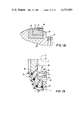
- FIG. 18 shows a detail section through a deep boring bit to illustrate the securing of a cutting member to the bit
- FIG. 19 shows a half axial section through a deep boring bit with cutting members secured to this in accordance with FIG. 18;
- FIGS. 20 and 21 as well as 22 and 23 are illustrations corresponding to FIGS. 18 and 19 to illustrate modified forms of embodiment and arrangements of the cutting members;
- FIG. 24 is a view of a deep boring bit with cutting members arranged in spiral form
- FIGS. 24a and 24b each show an enlarged illustration of the cutting members of FIG. 24 in views at right angles to one another;
- FIGS. 25 to 25b are illustrations corresponding to FIGS. 24 to 24b to illustrate a modified arrangement of the cutting members.
- FIG. 26 shows an example of an embodiment of a rotary boring bit constructed in the form of a core bit, illustrated in perspective.
- a sintered body 1 in the form of a cylinder which comprises a hard-metal shell 2, for example of tungsten carbide and a core 3 of polycrystalline diamond which is surrounded by the hard-metal shell 2 on all sides.
- a hard-metal shell 2 of the shaped body 1 forms a supporting portion 7 for a cutting portion 8 which is formed from the cut-out region of the core 3 of the shaped body 1 and which is surrounded by the supporting portion at the peripheral side and at the top and bottom or at both ends.
- the form of the cutting members 6 in the shape of quadrant-shaped segments is only selected by way of example in FIG. 1, and other suitable segment shapes may be selected instead, for example octantal-shaped.
- FIG. 2 in the left-hand half, the same shaped or sintered body 1 as in FIG. 1 is illustrated in principle but is divided by cutting lines 11, 12, 13 in radial planes into four shaped bodies 1a, 1b, 1c and 1d. All the shaped bodies 1a to 1d are divided as in the illustration in FIG. 1 along the cutting lines 9--9 and 10--10 extending in axial planes and at equal mutual angular distances apart.
- the cut faces 14a and 15a of the cutting members 14 and 15 are made plane or straight and have the shape of regular sectors.
- the sector-shaped cutting members 15 resulting from the shaped bodies 1b and 1c are alike in construction with the supporting portion 16 corresponding to the hard-metal shell 2 and the cutting portion 18 corresponding to the polycrystalline diamond core 3. In this case, the supporting portion 16 only surrounds the supporting portion 18 in the region of the peripheral arc of the cutting portion 18.
- the cutting members 14 resulting from the shaped bodies 1a and 1d are in turn like one another in construction.
- the supporting portion 17 of the cutting members 14 surrounds the cutting portion 19 over the peripheral arcuate portion and additionally, in contrast to the cutting members 15, at one of the two opposite ends of the cutting portion 19 extending in a radial plane.
- the form of embodiment of the sintered body 1 and of the cutting members 14 and 15 of FIG. 2a corresponds substantially to the forms of embodiment of FIG. 2 and differs from these only in that the cutting lines 9--9 and 10--10 are made not rectilinear but arcuate.
- the cutting members 14 and 15 of FIG. 2a do not have the shape of a regular sector of the sintered body as in the case of example shown in FIGS. 1 and 2, but in the case of the example of FIG. 2a, cutting members 14 and 15 in the form of modified or irregular sectors of the sintered body 1 are formed, the cut faces 14a and 15a defined by the cutting lines 9--9 and 10--10 being correspondingly curved.
- the sintered body 1 is first cut along the cutting lines 9--9 and 10--10 and then along the cutting lines 11, 12 and 13 or vice versa.
- the sintered body 1' has the shape of a sphere.
- This sphere again comprises the hard-metal shell 2 and the core 3 of polycrystalline diamond material.
- the sphere 1' can be divided by a cutting line 11a into two hemispheres and from these cutting members 15' can be cut out along the lines 9a and 10a which intersect in the middle of the core 3 and are disposed at right angles to one another in the example illustrated.
- the spherical sintered body 1' is provided with such an excision, from which the cutting members 15' result in the form of an eighth of a sphere of the shape illustrated separately in FIG. 2b at the bottom.
- This cutting member 15' again comprises a cutting portion 18' formed from polycrystalline diamond material and a supporting portion 16' of hard metal surrounding this as a jacket.
- the sintered body 1 may have the form of a polygonal straight prism instead of a cylinder, for example a parallelepiped, in which case the cutting lines 4--4 and 5--5 or 9--9 and 10--10 may appropriately be taken through axial outer edges of the prism, so the shaped body 1' may have the shape of a polyhedron instead of a sphere, a spheroid or the like body of revolution.
- the shape of such a polyhedron is optional but is preferably selected so that cuts passing through the core 3 are possible for the economical use of the sintered body for the purpose of forming substantially equal cutting members.
- FIG. 2c a sintered body 1" in the form of an octahedron with an excision forming an eighth of the octahedron is illustrated in FIG. 2c, the excision being illustrated separately in FIG. 2c at the bottom and forming the cutting member 15".
- This is again composed of the cutting portion 18" of polycrystalline diamond material corresponding to the core 3 and the supporting portion 16" corresponding to the hard-metal shell 2 of the sintered body 1".
- the form of embodiment of the sintered body 1 shown in FIG. 2d has the basic shape of a cylinder as in the case of the examples according to FIGS. 1, 2 and 2a.
- the cutting portion 3' embedded coaxially or concentrically in the supporting portion 2' of the sintered body 1 has a star-shaped base shape in cross-section with three ray-like wings 3a, 3b, and 3c.
- the cutting portion 3' is surrounded by the supporting portion 2' at the periphery and bottom.
- the wings 3a, 3b and 3c of the cutting portion 3' are rounded in the region of their ends and in the region of their transition at the base side.
- Phantom lines 4a which, in the example illustrated, are disposed at a mutual angular spacing of 120°, symbolize in the sintered body 1 in FIG. 2d the cutting lines or planes along which the sintered body 1 is severed to produce three cutting members in the example illustrated of the shape illustrated on the right-hand side in FIG. 2d.
- the cutting lines 4a extend in radial planes of the sintered body 1 centrally through the wings 3a, 3b, 3c of the star-shaped cutting portion 3'.
- the resulting cutting members correspond in their basic shape to those of the cutting members 14 and are therefore here likewise designated by the reference numeral 14.
- the cutting portion 19' has the modified shape with the two wing halves 3a' and 3b' of the original star-shaped cutting portion 3' of the sintered body 1 adjacent to one another at an angle.
- the supporting portion 17' surrounds the cutting portion 19' at the bottom and at the periphery with an arched portion engaging between the wing halves 3a' and 3b'.
- the cutting member 6 illustrated at the left-hand side in FIG. 2e corresponds in its basic construction to the cutting member 6 in FIG. 1 and like this is formed from a segment from a cylindrical sintered body 1.
- the supporting portion 7' surrounds the cutting portion 8' at both ends and at the periphery.
- the cutting member 6 is formed by quadrantal excisions from a sintered body, the cutting portion of which, as in the case of the example in FIG. 2d, has a star-shaped base shape in cross-section, but here comprises four ray-shaped wings which are again rounded in the region of their ends and in the region of their transition at the base side.
- the cutting lines for the production of the cutting members 6 according to FIG. 2e again extend centrally through the wings.
- two wing halves of the cutting portion 8' of the cutting member 6 which adjoin one another at an angle are designated by 8a and 8b.
- the cutting members illustrated on the right-hand side of FIG. 2e correspond in their basic construction to the cutting members 14 of FIGS. 2, 2a and 2b and are therefore again provided with the reference numeral 14, just as the same reference numerals are otherwise used for corresponding parts or regions.
- the wind halves of the cutting portion 19' which adjoin one another at right angles in the present example are designated by 19a and 19b.
- the procedure may be such that the cutting members 6 illustrated at the left-hand side of FIG. 2e is severed along a central transverse plane, or the cutting members 14 result from a sintered body 1 as shown in FIGS. 2 and 2a in accordance with the remarks made there.
- the same points of view with regard to the production apply also to the forms of embodiment of the cutting members 6' and 14' illustrated in FIG. 2f.
- the starting shape for these cutting members is a sintered body in the basic shape of a hexagonal prism with a cutting portion which accordingly comprises six ray-shaped wings.
- the same reference numerals as in FIG. 2e are used for the corresponding parts or regions of the cutting members 6' and 14' in FIG. 2f.
- the cutting member 6' is formed from a sixth of the hexagonal sintered body forming the initial workpiece, and the cutting lines are taken through the outside vertical edges and the centre of the hexagonal prism.
- the resulting vertical, lateral cut faces 14a are machined away in their outer region, however, starting approximately from the outer ends of the wing halves 8a and 8b and 19a and 19b so that they extend parallel to one another.
- the face 14b adjacent to the cutting portion 19' at the end is provided with a rounding towards the outside of the cutting member to produce a clearance face.
- the cutting members illustrated in FIGS. 2d, 2e and 2f use less diamond or cubic boron nitride or the like superhardened materials for the cutting portion in comparison with the other forms of embodiment and are suitable, in particular, for working soft formations in arrangements on the rotary boring bit as explained in the following FIGS. 4, 14 and 15, and in the case of an arrangement in accordance with the last-mentioned figure, the cutting members develop a plough effect.
- the cutting members described and illustrated so far can be secured to the boring tool in the most varied arrangements, the rear region of the supporting member remote from the cutting portion always being used for this securing.
- the cutting portion 8 offers a cutting edge 20 and cutting corners 21a and 21b.
- FIGS. 4, 5 and 6 the cutting member 6 is illustrated in cutting engagement with a formation 23 to be bored.
- the cutting action of the cutting edge 20 can be seen from FIG. 4 which shows that the polycrystalline diamond material of the cutting portion 8, which is surrounded by the supporting portion 7 of hard metal, develops its cutting action along the line defined by the cutting edge 20 and forms the boring 22.
- the cutting corners 21a or 21b can also be used for boring the formation 23, this being scraped or scratched by the particular cutting corner with the same feed direction.
- FIGS. 5 and 6 show such a mode of working.
- the cutting edge 21a has a scraping action
- the cutting edge 21b has a scratching effect on the formation 23 and scratches this substantially in V-shape with corresponding chip formation.
- the supporting portion 7 can be cut away at 7a to provide a flank as FIG. 5 shows. With the reverse oblique position of the cutting member 6 shown in FIG.
- the supporting portion 7 is cut away at 7b to provide or expose a V-shaped cutting face 8a of the cutting portion 8.
- the supporting portion 7 has a supporting function for the cutting portion 8 and does not participate in the cutting operation, even in its regions engaging over the two ends of the cutting portion 8, as can be seen, in particular, from FIG. 4.
- FIGS. 7 to 12 illustrate the possibilities of using the cutting member 15 which offers the cutting corners 24a and 24b, as well as the cutting edge 25, the cutting edges 26a and 26b and the cutting edges 27a and 27b (FIG. 7). The possible cutting relationships are illustrated in FIGS. 8 to 12.
- a chip 28 is parted off from the formation 29 by means of the cutting edge 25 in front of the cutting face 24 of the cutting portion 18, the flank of which is designated by 26.
- the cutting portion 18 acts like a plough, in that it cuts with the cutting edges 25, 26a and 27a. In an arrangement turned through 180°, the cutting member 15 cuts accordingly with the cutting edge 25 and with the cutting edges 26b and 27b. In both cases, a complex three-dimensional chip formation 52 results.
- the cutting portion 18 of the cutting member 15 cuts with the cutting edge 26a.
- the cutting edge 27a or 26a or 27b can be brought into engagement with the formation 29 instead of the cutting edge 26a.
- the cutting face 24 is in the form of a circular segment.
- the cutting member 15 is suitable for scratching the formation 29 with a feed direction towards the left, and, in accordance with the example illustrated, the cutting corner 24a, or with a reverse oblique position the cutting corner 24b, is in engagement with the formation 29.
- a scraping action is effected on the formation 29 by the tip or cutting corner 24a. It will be understood that with an appropriately reversed oblique position, a scraping action on the formation 29 can be effected with the cutting corner 24b.
- the cutting portion 19 of the cutting member 14 comprises the cutting edges 31a, 31b and 32 as well as the cutting corners 33a and 33b.
- the geometrical relationships at the cutting portion 19 are illustrated in FIGS. 14 to 17 and correspond to the illustrations in FIGS. 8 to 12.
- the cutting edge 32 cuts forming a chip 28, while in the arrangement of FIG. 15, the cutting edges 31a, 31b and 32 cut forming the chip 52 and the cutting member 14 again has a plough effect.
- FIG. 16 illustrates the scratching of the formation 29 by means of the cutting corner 33a.
- FIG. 17 illustrates a scraping of the formation 29 by means of the cutting edge 33b, the supporting portion 17 again being cut away at 17a to provide a flank.
- the feed direction of the cutting member 14 is towards the left in both cases.
- the constructions and arrangements described above of the cutting members are selected according to the intended use and depending on the boring conditions of the formation. Thus with hard rock formations, scratching or scraping operations are preferred for the boring operation. These can be achieved with arrangements according to FIGS. 5, 6, 11, 12 and 16, 17, and in addition to the cutting members shown in these figures, the cutting members 15' and 15" can be used to particular advantage for such cutting operations.
- the arrangements of the cutting members as illustrated in FIGS. 9 and 15 offer themselves, according to which a ploughing action of the cutting members takes place. In this case, the cutting members may also be arranged so that an asymmetrical plough effect results.
- arrangements as shown in FIGS. 4, 8, 10 and 14 may be used, as a result of which the chip formation illustrated is achieved.
- FIG. 18 illustrates, with reference to the cutting member 14, a possibility for securing the cutting members according to the invention to a deep boring bit.
- the cutting member 14 is connected by its supporting portion 17 to an appropriately shaped holding member 34, by adhesion or soldering.
- the holding member 34 is sintered into a matrix member 35 of the boring bit.
- a rib 36 of the matrix member 35 protects the soldering seam between the cutting member 14 and the holding member 34 from erosion as a result of the flushing liquid emerging from the usual flushing nozzles of the boring bit, one of which is illustrated at 37.
- the cutting members may be provided with a surface coating of nickel, copper or cobalt, for example, which encourages a diffusion binding and which may be applied physically, chemically or galvanically.
- a surface coating encourages the flow of the solder in the soldering gaps between the contact faces of the supporting portion 17 and the holding member 34 and improves the production of satisfactory soldered connections.
- FIG. 19 a boring bit equipped with cutting members 14 in the manner explained with reference to FIG. 18 is illustrated diagrammatically in section. From this, the basic body 38 of the bit with the matrix mamber 35 and the cutting members 14 and the holding member 34 with the rib 36 situated in front of the cutting member 14 can be seen. The cutting movement results from rotation of the boring bit about the axis X--X.
- FIG. 20 A modified form of securing the cutting member 14 in the boring bit is illustrated in FIG. 20, wherein the cutting member 14 is inserted in accordance with the illustration in FIG. 6.
- the cutting member 14 is secured to a holding member 40 by soldering or adhesion.
- the soldered or adhesive joint is secured against erosion by the flushing stream emerging from the nozzle 41 by means of a rib 42.
- the holding member 40 is sintered into the basic body 43 of the bit in a furnace process.
- a rib 44 of the basic body of the bit is provided behind the holding member 40 and imparts the necessary rigidity with the wing or rib construction selected in the examples illustrated.
- FIG. 21 In the sectional illustration according to FIG. 21 through a boring bit equipped with cutting members 14 in accordance with FIG. 20, holding member 40, cutting members 14 and nozzles 41 and the two ribs 42 and 44 can be seen.
- the cutting members 14 and/or 15 may also be disposed on a stepped tool as shown in FIGS. 22 and 23.
- the cutting conditions can be selected in principle in accordance with the arrangements illustrated in FIGS. 11 and 12 or 16 and 17.
- the cutting members 15 is soldered or stuck to a holding member 45 sintered into the basic body of the boring bit.
- the holding member 45 effects a rear supporting of the cutting member 15. If the cutting member 14 is used, the supporting of the cutting member by a holding member 46 at the side remote from the cutting face can be dispensed with because here the cutting portion 19 of the cutting member 14 is supported at the back by the supporting portion 17.
- FIG. 23 shows a stepped tool equipped with cutting members according to FIG. 2.
- FIGS. 24, 24a and 24b The construction of a deep boring bit with cutting members 14 and/or 15 set spirally, the cutting principle of which is selected in accordance with the illustrations in FIGS. 8 and 14, is illustrated in FIGS. 24, 24a and 24b, using cutting members 15.
- the cutting members 15 are disposed over the bit on a helical spiral or the like and are again secured to a supporting member 47 by soldering or adhesion.
- the cutting members 14 and/or 15 are inserted in arrangements according to FIGS. 9 and 15, in which they develop a plough action.
- the arrangement may be such that only the cutting portion 19 projects from the matrix member of the bit.
- the corresponding support of the cutting member 14 is effected through a holding member 48 and a rib or support 49 forming part of the matrix member. The same applies accordingly to the embodiment of FIG. 24.
- FIG. 26 The use of the cutting members described and illustrated in a rotary boring bit constructed in the form of a core bit is illustrated in FIG. 26, using cutting members 15.
- the cutting members 15 are soldered or stuck to a holding member 50 being distributed with equal spacing over an annular end face.
- the holding member 50 is rigidly connected to a matrix shaped member 51 of the core bit by infiltration in the example illustrated.
- the material of the cutting members is adapted to the basic body 35 of the bit in such a manner that the supporting portion 7, 16 or 17 of the cutting members has a lower wear resistance in comparison with its cutting portion 8, 18 or 19 and a higher wear resistance in comparison with the base member 35. If the cutting members are each secured to the base member 35 by means of a holding member, as illustrated in FIGS. 18 to 25 with reference to the holding members 34, 40, 45 and 46, then with such a construction, it is provided that the particular holding member has a lower wear resistance in comparison with the supporting portion 7, 16 or 17 of the cutting member and a higher wear resistance in comparison with the basic member 35.
- the holding member preferably has a lower material rigidity in comparison with the supporting portion 7, 16 or 17 and a higher material rigidity in comparison with the basic body 35.
- tungsten carbide for example, bonded in alloys on a copper base, for example brass or bronze alloys, as well as those with various proportions of nickel, cobalt, tin, zinc, manganese, iron and silver may be used for the basic body of the bit.
- Tungsten carbide comes into consideration primarily for the supporting portion 7, 16 or 17 of the cutting members.
- An appropriately modified composition can be used for the holding members 34, 40, 45 or 46.
- the latter may also be provided with a coating, for example in the form of nickel, copper or cobalt, which encourages a diffusion binding, in order to improve in this manner the strength of a soldered connection between the holding member and the basic body 35 of the bit on the one hand and the supporting portion 7, 16 or 17 of the cutting members on the other hand.
- a coating for example in the form of nickel, copper or cobalt, which encourages a diffusion binding, in order to improve in this manner the strength of a soldered connection between the holding member and the basic body 35 of the bit on the one hand and the supporting portion 7, 16 or 17 of the cutting members on the other hand.
- the supporting portion may be prefabricated in the form of an at least partially pre-shaped sintered shaped body, for example in the form of a cylinder closed at the bottom, after which the cavity in this pre-shaped body is filled with a mass of diamond particles and cobalt powder for example, which is then sintered in.
- the pre-shaped body can be completed.
- the cutting portion in the form of a separate, sintered pre-shaped body and either to insert it in a pre-shaped body forming the supporting portion and then to unite it with the sintered body completing the supporting portion, using compound substances such as zirconium, cobalt and nickel, or to sinter it into the supporting portion during the sintering of this.
- the cutting members employed in this invention can be made by the method shown in U.S. Pat. Nos. 3,745,623; 4,063,909; and 3,743,489, wherein diamond or cubic boron nitride powders are compacted, along with a supporting hard carbide material, under pressures and temperatures in the diamond stable region of the pressure temperature diagram.
Abstract
Description
Claims (12)
Applications Claiming Priority (2)
| Application Number | Priority Date | Filing Date | Title |
|---|---|---|---|
| DE2910347 | 1979-03-16 | ||
| DE2910347A DE2910347C2 (en) | 1978-04-21 | 1979-03-16 | Rotary drill bit for deep drilling in rock |
Publications (1)
| Publication Number | Publication Date |
|---|---|
| US4373593A true US4373593A (en) | 1983-02-15 |
Family
ID=6065567
Family Applications (1)
| Application Number | Title | Priority Date | Filing Date |
|---|---|---|---|
| US06/128,998 Expired - Lifetime US4373593A (en) | 1979-03-16 | 1980-03-10 | Drill bit |
Country Status (4)
| Country | Link |
|---|---|
| US (1) | US4373593A (en) |
| JP (1) | JPS55129586A (en) |
| CA (1) | CA1132971A (en) |
| MX (1) | MX151243A (en) |
Cited By (99)
| Publication number | Priority date | Publication date | Assignee | Title |
|---|---|---|---|---|
| US4440246A (en) * | 1981-04-11 | 1984-04-03 | Christensen, Inc. | Cutting member for rotary drill bits |
| EP0118127A2 (en) * | 1983-03-07 | 1984-09-12 | Eastman Christensen Company | An improved tooth design to avoid shearing stresses |
| EP0119620A2 (en) * | 1983-03-21 | 1984-09-26 | Eastman Christensen Company | Improved tooth design using cylindrical diamond cutting elements |
| EP0121124A2 (en) * | 1983-03-07 | 1984-10-10 | Eastman Christensen Company | An improved diamond cutting element in a rotating bit |
| EP0121802A2 (en) * | 1983-03-14 | 1984-10-17 | Eastman Christensen Company | Tooth configuration for an earth boring bit |
| EP0127077A2 (en) * | 1983-05-20 | 1984-12-05 | Eastman Christensen Company | A rotatable drill bit |
| EP0149530A2 (en) * | 1984-01-16 | 1985-07-24 | CDP, Ltd. | Self sharpening drag bit assembly |
| US4550791A (en) * | 1983-10-03 | 1985-11-05 | Kennametal Inc. | Two-prong rotary bit, especially for use with roof drills, and insert therefor |
| US4550790A (en) * | 1983-02-28 | 1985-11-05 | Norton Christensen, Inc. | Diamond rotating bit |
| EP0186408A2 (en) * | 1984-12-22 | 1986-07-02 | Reed Tool Company Limited | Improvements in or relating to cutting elements for rotary drill bits |
| US4702649A (en) * | 1986-02-27 | 1987-10-27 | General Electric Company | Polycrystalline diamond and CBN cutting tools |
| US4714385A (en) * | 1986-02-27 | 1987-12-22 | General Electric Company | Polycrystalline diamond and CBN cutting tools |
| FR2620487A1 (en) * | 1987-09-14 | 1989-03-17 | Vennin Henri | Rotary monobloc boring bit |
| US4858706A (en) * | 1987-09-15 | 1989-08-22 | Lebourgh Maurice P | Diamond drill bit with hemispherically shaped diamond inserts |
| EP0336698A2 (en) * | 1988-04-05 | 1989-10-11 | Camco Drilling Group Limited | Cutting element for a rotary drill bit, and method for manufacturing such an element |
| US4926950A (en) * | 1986-03-27 | 1990-05-22 | Shell Oil Company | Method for monitoring the wear of a rotary type drill bit |
| US4989578A (en) * | 1989-08-30 | 1991-02-05 | Lebourg Maurice P | Method for forming diamond cutting elements for a diamond drill bit |
| US4997049A (en) * | 1988-08-15 | 1991-03-05 | Klaus Tank | Tool insert |
| US5025871A (en) * | 1989-04-05 | 1991-06-25 | Aulette Stewart | Drilling method and rotary drill bit crown |
| DE4100351A1 (en) * | 1990-01-10 | 1991-07-11 | Nippon Oils & Fats Co Ltd | Cutting tool with improved binding strength - made of cutting edge sintered to support part slotted into groove of base and soldered in place |
| US5092310A (en) * | 1989-05-23 | 1992-03-03 | General Electric Company | Mining pick |
| US5115873A (en) * | 1991-01-24 | 1992-05-26 | Baker Hughes Incorporated | Method and appartus for directing drilling fluid to the cutting edge of a cutter |
| US5119714A (en) * | 1991-03-01 | 1992-06-09 | Hughes Tool Company | Rotary rock bit with improved diamond filled compacts |
| GB2251879A (en) * | 1988-04-05 | 1992-07-22 | Camco Drilling Group Ltd | Manufacturing culling elements for rotary drill bits |
| US5159857A (en) * | 1991-03-01 | 1992-11-03 | Hughes Tool Company | Fixed cutter bit with improved diamond filled compacts |
| US5183362A (en) * | 1990-01-10 | 1993-02-02 | Nippon Oil And Fats Co., Ltd. | Cutting tool assembly |
| US5248006A (en) * | 1991-03-01 | 1993-09-28 | Baker Hughes Incorporated | Rotary rock bit with improved diamond-filled compacts |
| US5247923A (en) * | 1992-03-09 | 1993-09-28 | Lebourg Maurice P | Method of forming a diamond drill bit element using laser trimming |
| US5273125A (en) * | 1991-03-01 | 1993-12-28 | Baker Hughes Incorporated | Fixed cutter bit with improved diamond filled compacts |
| US5348108A (en) * | 1991-03-01 | 1994-09-20 | Baker Hughes Incorporated | Rolling cone bit with improved wear resistant inserts |
| US5355750A (en) * | 1991-03-01 | 1994-10-18 | Baker Hughes Incorporated | Rolling cone bit with improved wear resistant inserts |
| US5429199A (en) * | 1992-08-26 | 1995-07-04 | Kennametal Inc. | Cutting bit and cutting insert |
| FR2735522A1 (en) * | 1995-06-16 | 1996-12-20 | Total Sa | MONOBLOCK DRILLING TOOL SIZE |
| EP0718462A3 (en) * | 1994-12-19 | 1996-12-27 | Baker Hughes Inc | Drill bit cutting element and method for mounting a cutting element on a drill bit |
| EP0707130A3 (en) * | 1994-10-15 | 1997-07-02 | Camco Drilling Group Ltd | Rotary drill bits |
| US6062325A (en) * | 1997-04-21 | 2000-05-16 | Camco International (Uk) Limited | Rotary drill bits |
| US6135681A (en) * | 1998-08-21 | 2000-10-24 | Allied Machine & Engineering | Flat bottom tool |
| US6146476A (en) * | 1999-02-08 | 2000-11-14 | Alvord-Polk, Inc. | Laser-clad composite cutting tool and method |
| US6258139B1 (en) * | 1999-12-20 | 2001-07-10 | U S Synthetic Corporation | Polycrystalline diamond cutter with an integral alternative material core |
| US6544308B2 (en) | 2000-09-20 | 2003-04-08 | Camco International (Uk) Limited | High volume density polycrystalline diamond with working surfaces depleted of catalyzing material |
| US20030111273A1 (en) * | 1999-11-29 | 2003-06-19 | Volker Richert | Impregnated rotary drag bit |
| US6601662B2 (en) | 2000-09-20 | 2003-08-05 | Grant Prideco, L.P. | Polycrystalline diamond cutters with working surfaces having varied wear resistance while maintaining impact strength |
| GB2356655B (en) * | 1999-11-29 | 2004-05-26 | Baker Hughes Inc | Impregnated bit with PDC cutters in a cone area |
| US20050230156A1 (en) * | 2003-12-05 | 2005-10-20 | Smith International, Inc. | Thermally-stable polycrystalline diamond materials and compacts |
| US20050247492A1 (en) * | 2004-04-30 | 2005-11-10 | Smith International, Inc. | Cutter having shaped working surface with varying edge chamber |
| US20050263328A1 (en) * | 2004-05-06 | 2005-12-01 | Smith International, Inc. | Thermally stable diamond bonded materials and compacts |
| US20060060391A1 (en) * | 2004-09-21 | 2006-03-23 | Smith International, Inc. | Thermally stable diamond polycrystalline diamond constructions |
| US20060060390A1 (en) * | 2004-09-21 | 2006-03-23 | Smith International, Inc. | Thermally stable diamond polycrystalline diamond constructions |
| US20060157285A1 (en) * | 2005-01-17 | 2006-07-20 | Us Synthetic Corporation | Polycrystalline diamond insert, drill bit including same, and method of operation |
| US20060266559A1 (en) * | 2005-05-26 | 2006-11-30 | Smith International, Inc. | Polycrystalline diamond materials having improved abrasion resistance, thermal stability and impact resistance |
| US20070175672A1 (en) * | 2006-01-30 | 2007-08-02 | Eyre Ronald K | Cutting elements and bits incorporating the same |
| US20070187155A1 (en) * | 2006-02-09 | 2007-08-16 | Smith International, Inc. | Thermally stable ultra-hard polycrystalline materials and compacts |
| US20080073126A1 (en) * | 2006-09-21 | 2008-03-27 | Smith International, Inc. | Polycrystalline diamond composites |
| US20080179109A1 (en) * | 2005-01-25 | 2008-07-31 | Smith International, Inc. | Cutting elements formed from ultra hard materials having an enhanced construction |
| US20080223623A1 (en) * | 2007-02-06 | 2008-09-18 | Smith International, Inc. | Polycrystalline diamond constructions having improved thermal stability |
| US20080223621A1 (en) * | 2005-05-26 | 2008-09-18 | Smith International, Inc. | Thermally stable ultra-hard material compact construction |
| US20080230280A1 (en) * | 2007-03-21 | 2008-09-25 | Smith International, Inc. | Polycrystalline diamond having improved thermal stability |
| US20090022952A1 (en) * | 2005-01-27 | 2009-01-22 | Smith International, Inc. | Novel cutting structures |
| US20090071727A1 (en) * | 2007-09-18 | 2009-03-19 | Smith International, Inc. | Ultra-hard composite constructions comprising high-density diamond surface |
| US20090090563A1 (en) * | 2007-10-04 | 2009-04-09 | Smith International, Inc. | Diamond-bonded constrcutions with improved thermal and mechanical properties |
| US20090107732A1 (en) * | 2007-10-31 | 2009-04-30 | Mcclain Eric E | Impregnated rotary drag bit and related methods |
| US20090152017A1 (en) * | 2007-12-17 | 2009-06-18 | Smith International, Inc. | Polycrystalline diamond construction with controlled gradient metal content |
| US20090178855A1 (en) * | 2005-02-08 | 2009-07-16 | Smith International, Inc. | Thermally stable polycrystalline diamond cutting elements and bits incorporating the same |
| US20100084197A1 (en) * | 2008-10-03 | 2010-04-08 | Smith International, Inc. | Diamond bonded construction with thermally stable region |
| US20100098505A1 (en) * | 2008-10-17 | 2010-04-22 | Garrick Richard M | Shielded pcd or pcbn cutting tools |
| US7726421B2 (en) | 2005-10-12 | 2010-06-01 | Smith International, Inc. | Diamond-bonded bodies and compacts with improved thermal stability and mechanical strength |
| US20100242375A1 (en) * | 2009-03-30 | 2010-09-30 | Hall David R | Double Sintered Thermally Stable Polycrystalline Diamond Cutting Elements |
| US20100281782A1 (en) * | 2009-05-06 | 2010-11-11 | Keshavan Madapusi K | Methods of making and attaching tsp material for forming cutting elements, cutting elements having such tsp material and bits incorporating such cutting elements |
| US20100282519A1 (en) * | 2009-05-06 | 2010-11-11 | Youhe Zhang | Cutting elements with re-processed thermally stable polycrystalline diamond cutting layers, bits incorporating the same, and methods of making the same |
| US20100320006A1 (en) * | 2009-06-18 | 2010-12-23 | Guojiang Fan | Polycrystalline diamond cutting elements with engineered porosity and method for manufacturing such cutting elements |
| US20110056141A1 (en) * | 2009-09-08 | 2011-03-10 | Us Synthetic Corporation | Superabrasive Elements and Methods for Processing and Manufacturing the Same Using Protective Layers |
| US20110155472A1 (en) * | 2009-12-28 | 2011-06-30 | Baker Hughes Incorporated | Earth-boring tools having differing cutting elements on a blade and related methods |
| US20110192651A1 (en) * | 2010-02-05 | 2011-08-11 | Baker Hughes Incorporated | Shaped cutting elements on drill bits and other earth-boring tools, and methods of forming same |
| US8020643B2 (en) | 2005-09-13 | 2011-09-20 | Smith International, Inc. | Ultra-hard constructions with enhanced second phase |
| US8066087B2 (en) | 2006-05-09 | 2011-11-29 | Smith International, Inc. | Thermally stable ultra-hard material compact constructions |
| US20110308865A1 (en) * | 2010-06-17 | 2011-12-22 | American National Carbide Co. | Downhole cutting tool, cutting elements and method |
| US8377157B1 (en) | 2009-04-06 | 2013-02-19 | Us Synthetic Corporation | Superabrasive articles and methods for removing interstitial materials from superabrasive materials |
| CN103157797A (en) * | 2013-03-19 | 2013-06-19 | 河南富耐克超硬材料股份有限公司 | Tool bit blank and synthetic process thereof and synthetic mold thereof and tool bit production method |
| US8561727B1 (en) * | 2009-10-28 | 2013-10-22 | Us Synthetic Corporation | Superabrasive cutting elements and systems and methods for manufacturing the same |
| US8667866B2 (en) | 2009-12-31 | 2014-03-11 | Diamond Innovations, Inc. | Machining tool blank and method of forming |
| US8741010B2 (en) | 2011-04-28 | 2014-06-03 | Robert Frushour | Method for making low stress PDC |
| US8828110B2 (en) | 2011-05-20 | 2014-09-09 | Robert Frushour | ADNR composite |
| US8851207B2 (en) | 2011-05-05 | 2014-10-07 | Baker Hughes Incorporated | Earth-boring tools and methods of forming such earth-boring tools |
| US8858665B2 (en) | 2011-04-28 | 2014-10-14 | Robert Frushour | Method for making fine diamond PDC |
| US8951317B1 (en) | 2009-04-27 | 2015-02-10 | Us Synthetic Corporation | Superabrasive elements including ceramic coatings and methods of leaching catalysts from superabrasive elements |
| US8974559B2 (en) | 2011-05-12 | 2015-03-10 | Robert Frushour | PDC made with low melting point catalyst |
| US9022149B2 (en) | 2010-08-06 | 2015-05-05 | Baker Hughes Incorporated | Shaped cutting elements for earth-boring tools, earth-boring tools including such cutting elements, and related methods |
| US9061264B2 (en) | 2011-05-19 | 2015-06-23 | Robert H. Frushour | High abrasion low stress PDC |
| US9144886B1 (en) | 2011-08-15 | 2015-09-29 | Us Synthetic Corporation | Protective leaching cups, leaching trays, and methods for processing superabrasive elements using protective leaching cups and leaching trays |
| US9316058B2 (en) | 2012-02-08 | 2016-04-19 | Baker Hughes Incorporated | Drill bits and earth-boring tools including shaped cutting elements |
| US9394747B2 (en) | 2012-06-13 | 2016-07-19 | Varel International Ind., L.P. | PCD cutters with improved strength and thermal stability |
| US9550276B1 (en) | 2013-06-18 | 2017-01-24 | Us Synthetic Corporation | Leaching assemblies, systems, and methods for processing superabrasive elements |
| US9789587B1 (en) | 2013-12-16 | 2017-10-17 | Us Synthetic Corporation | Leaching assemblies, systems, and methods for processing superabrasive elements |
| US9908215B1 (en) | 2014-08-12 | 2018-03-06 | Us Synthetic Corporation | Systems, methods and assemblies for processing superabrasive materials |
| US10011000B1 (en) | 2014-10-10 | 2018-07-03 | Us Synthetic Corporation | Leached superabrasive elements and systems, methods and assemblies for processing superabrasive materials |
| US10723626B1 (en) | 2015-05-31 | 2020-07-28 | Us Synthetic Corporation | Leached superabrasive elements and systems, methods and assemblies for processing superabrasive materials |
| US10807913B1 (en) | 2014-02-11 | 2020-10-20 | Us Synthetic Corporation | Leached superabrasive elements and leaching systems methods and assemblies for processing superabrasive elements |
| US10900291B2 (en) | 2017-09-18 | 2021-01-26 | Us Synthetic Corporation | Polycrystalline diamond elements and systems and methods for fabricating the same |
| US11766761B1 (en) | 2014-10-10 | 2023-09-26 | Us Synthetic Corporation | Group II metal salts in electrolytic leaching of superabrasive materials |
Families Citing this family (2)
| Publication number | Priority date | Publication date | Assignee | Title |
|---|---|---|---|---|
| JPS6129832Y2 (en) * | 1979-05-18 | 1986-09-02 | ||
| JP4713930B2 (en) * | 2005-01-07 | 2011-06-29 | 大成建設株式会社 | Dredge equipment |
Citations (8)
| Publication number | Priority date | Publication date | Assignee | Title |
|---|---|---|---|---|
| US1952002A (en) * | 1933-04-22 | 1934-03-20 | Jessop Steel Company | Process of manufacturing composite steel articles |
| GB529529A (en) * | 1939-06-02 | 1940-11-22 | J K Smit & Sons Inc | Art of setting diamonds and making diamond tools |
| US2275021A (en) * | 1938-07-01 | 1942-03-03 | Budd Induction Heating Inc | Process of making tools |
| US3106973A (en) * | 1960-09-26 | 1963-10-15 | Christensen Diamond Prod Co | Rotary drill bits |
| GB980799A (en) * | 1961-11-24 | 1965-01-20 | Diamant Boart Sa | Drill bits |
| US3702573A (en) * | 1969-03-19 | 1972-11-14 | Kennametal Inc | Cermet product and method and apparatus for the manufacture thereof |
| US3745623A (en) * | 1971-12-27 | 1973-07-17 | Gen Electric | Diamond tools for machining |
| US4200159A (en) * | 1977-04-30 | 1980-04-29 | Christensen, Inc. | Cutter head, drill bit and similar drilling tools |
-
1980
- 1980-03-10 US US06/128,998 patent/US4373593A/en not_active Expired - Lifetime
- 1980-03-14 CA CA347,648A patent/CA1132971A/en not_active Expired
- 1980-03-14 MX MX181581A patent/MX151243A/en unknown
- 1980-03-15 JP JP3217280A patent/JPS55129586A/en active Granted
Patent Citations (8)
| Publication number | Priority date | Publication date | Assignee | Title |
|---|---|---|---|---|
| US1952002A (en) * | 1933-04-22 | 1934-03-20 | Jessop Steel Company | Process of manufacturing composite steel articles |
| US2275021A (en) * | 1938-07-01 | 1942-03-03 | Budd Induction Heating Inc | Process of making tools |
| GB529529A (en) * | 1939-06-02 | 1940-11-22 | J K Smit & Sons Inc | Art of setting diamonds and making diamond tools |
| US3106973A (en) * | 1960-09-26 | 1963-10-15 | Christensen Diamond Prod Co | Rotary drill bits |
| GB980799A (en) * | 1961-11-24 | 1965-01-20 | Diamant Boart Sa | Drill bits |
| US3702573A (en) * | 1969-03-19 | 1972-11-14 | Kennametal Inc | Cermet product and method and apparatus for the manufacture thereof |
| US3745623A (en) * | 1971-12-27 | 1973-07-17 | Gen Electric | Diamond tools for machining |
| US4200159A (en) * | 1977-04-30 | 1980-04-29 | Christensen, Inc. | Cutter head, drill bit and similar drilling tools |
Cited By (209)
| Publication number | Priority date | Publication date | Assignee | Title |
|---|---|---|---|---|
| US4440246A (en) * | 1981-04-11 | 1984-04-03 | Christensen, Inc. | Cutting member for rotary drill bits |
| US4550790A (en) * | 1983-02-28 | 1985-11-05 | Norton Christensen, Inc. | Diamond rotating bit |
| EP0121124A2 (en) * | 1983-03-07 | 1984-10-10 | Eastman Christensen Company | An improved diamond cutting element in a rotating bit |
| US4515226A (en) * | 1983-03-07 | 1985-05-07 | Norton Christensen, Inc. | Tooth design to avoid shearing stresses |
| EP0118127A2 (en) * | 1983-03-07 | 1984-09-12 | Eastman Christensen Company | An improved tooth design to avoid shearing stresses |
| EP0118127A3 (en) * | 1983-03-07 | 1986-01-22 | Norton Christensen, Inc. | An improved tooth design to avoid shearing stresses |
| EP0121124A3 (en) * | 1983-03-07 | 1986-01-29 | Norton Christensen, Inc. | An improved diamond cutting element in a rotating bit |
| EP0121802A2 (en) * | 1983-03-14 | 1984-10-17 | Eastman Christensen Company | Tooth configuration for an earth boring bit |
| EP0121802A3 (en) * | 1983-03-14 | 1986-01-29 | Norton Christensen, Inc. | Tooth configuration for an earth boring bit |
| EP0119620A2 (en) * | 1983-03-21 | 1984-09-26 | Eastman Christensen Company | Improved tooth design using cylindrical diamond cutting elements |
| EP0119620A3 (en) * | 1983-03-21 | 1986-02-12 | Norton Christensen, Inc. | Improved tooth design using cylindrical diamond cutting elements |
| EP0127077A3 (en) * | 1983-05-20 | 1986-02-05 | Norton Christensen, Inc. | Cutter configuration for a gage-to-shoulder transition and face pattern |
| EP0127077A2 (en) * | 1983-05-20 | 1984-12-05 | Eastman Christensen Company | A rotatable drill bit |
| US4550791A (en) * | 1983-10-03 | 1985-11-05 | Kennametal Inc. | Two-prong rotary bit, especially for use with roof drills, and insert therefor |
| EP0149530A2 (en) * | 1984-01-16 | 1985-07-24 | CDP, Ltd. | Self sharpening drag bit assembly |
| EP0149530A3 (en) * | 1984-01-16 | 1986-02-05 | CDP, Ltd. | Self sharpening drag bit assembly |
| US4928777A (en) * | 1984-12-22 | 1990-05-29 | Nl Petroleum Products Limited | Cutting elements for rotary drill bits |
| EP0186408A2 (en) * | 1984-12-22 | 1986-07-02 | Reed Tool Company Limited | Improvements in or relating to cutting elements for rotary drill bits |
| EP0186408A3 (en) * | 1984-12-22 | 1987-07-01 | Nl Petroleum Products Limited | Improvements in or relating to cutting elements for rotary drill bits |
| US4702649A (en) * | 1986-02-27 | 1987-10-27 | General Electric Company | Polycrystalline diamond and CBN cutting tools |
| US4714385A (en) * | 1986-02-27 | 1987-12-22 | General Electric Company | Polycrystalline diamond and CBN cutting tools |
| US4926950A (en) * | 1986-03-27 | 1990-05-22 | Shell Oil Company | Method for monitoring the wear of a rotary type drill bit |
| FR2620487A1 (en) * | 1987-09-14 | 1989-03-17 | Vennin Henri | Rotary monobloc boring bit |
| US4858706A (en) * | 1987-09-15 | 1989-08-22 | Lebourgh Maurice P | Diamond drill bit with hemispherically shaped diamond inserts |
| EP0336698A2 (en) * | 1988-04-05 | 1989-10-11 | Camco Drilling Group Limited | Cutting element for a rotary drill bit, and method for manufacturing such an element |
| EP0336698A3 (en) * | 1988-04-05 | 1990-10-31 | Reed Tool Company Limited | Cutting element for a rotary drill bit, and method for manufacturing such an element |
| GB2251879A (en) * | 1988-04-05 | 1992-07-22 | Camco Drilling Group Ltd | Manufacturing culling elements for rotary drill bits |
| GB2251879B (en) * | 1988-04-05 | 1992-11-11 | Camco Drilling Group Ltd | Improvements in or relating to cutting elements for rotary drill bits |
| US4997049A (en) * | 1988-08-15 | 1991-03-05 | Klaus Tank | Tool insert |
| US5025871A (en) * | 1989-04-05 | 1991-06-25 | Aulette Stewart | Drilling method and rotary drill bit crown |
| US5092310A (en) * | 1989-05-23 | 1992-03-03 | General Electric Company | Mining pick |
| US4989578A (en) * | 1989-08-30 | 1991-02-05 | Lebourg Maurice P | Method for forming diamond cutting elements for a diamond drill bit |
| DE4100351A1 (en) * | 1990-01-10 | 1991-07-11 | Nippon Oils & Fats Co Ltd | Cutting tool with improved binding strength - made of cutting edge sintered to support part slotted into groove of base and soldered in place |
| US5183362A (en) * | 1990-01-10 | 1993-02-02 | Nippon Oil And Fats Co., Ltd. | Cutting tool assembly |
| US5115873A (en) * | 1991-01-24 | 1992-05-26 | Baker Hughes Incorporated | Method and appartus for directing drilling fluid to the cutting edge of a cutter |
| US5119714A (en) * | 1991-03-01 | 1992-06-09 | Hughes Tool Company | Rotary rock bit with improved diamond filled compacts |
| US5159857A (en) * | 1991-03-01 | 1992-11-03 | Hughes Tool Company | Fixed cutter bit with improved diamond filled compacts |
| US5248006A (en) * | 1991-03-01 | 1993-09-28 | Baker Hughes Incorporated | Rotary rock bit with improved diamond-filled compacts |
| US5273125A (en) * | 1991-03-01 | 1993-12-28 | Baker Hughes Incorporated | Fixed cutter bit with improved diamond filled compacts |
| US5348108A (en) * | 1991-03-01 | 1994-09-20 | Baker Hughes Incorporated | Rolling cone bit with improved wear resistant inserts |
| US5355750A (en) * | 1991-03-01 | 1994-10-18 | Baker Hughes Incorporated | Rolling cone bit with improved wear resistant inserts |
| US5247923A (en) * | 1992-03-09 | 1993-09-28 | Lebourg Maurice P | Method of forming a diamond drill bit element using laser trimming |
| US5429199A (en) * | 1992-08-26 | 1995-07-04 | Kennametal Inc. | Cutting bit and cutting insert |
| EP0707130A3 (en) * | 1994-10-15 | 1997-07-02 | Camco Drilling Group Ltd | Rotary drill bits |
| EP0718462A3 (en) * | 1994-12-19 | 1996-12-27 | Baker Hughes Inc | Drill bit cutting element and method for mounting a cutting element on a drill bit |
| FR2735522A1 (en) * | 1995-06-16 | 1996-12-20 | Total Sa | MONOBLOCK DRILLING TOOL SIZE |
| WO1997000372A1 (en) * | 1995-06-16 | 1997-01-03 | Total | Integral drilling tool bit |
| US5823277A (en) * | 1995-06-16 | 1998-10-20 | Total | Cutting edge for monobloc drilling tools |
| US6062325A (en) * | 1997-04-21 | 2000-05-16 | Camco International (Uk) Limited | Rotary drill bits |
| US6135681A (en) * | 1998-08-21 | 2000-10-24 | Allied Machine & Engineering | Flat bottom tool |
| US6146476A (en) * | 1999-02-08 | 2000-11-14 | Alvord-Polk, Inc. | Laser-clad composite cutting tool and method |
| US6402438B1 (en) | 1999-02-08 | 2002-06-11 | Alvord-Polk, Inc. | Composite Cutting Tool |
| GB2356655B (en) * | 1999-11-29 | 2004-05-26 | Baker Hughes Inc | Impregnated bit with PDC cutters in a cone area |
| US6843333B2 (en) | 1999-11-29 | 2005-01-18 | Baker Hughes Incorporated | Impregnated rotary drag bit |
| US20030111273A1 (en) * | 1999-11-29 | 2003-06-19 | Volker Richert | Impregnated rotary drag bit |
| US6258139B1 (en) * | 1999-12-20 | 2001-07-10 | U S Synthetic Corporation | Polycrystalline diamond cutter with an integral alternative material core |
| US20030235691A1 (en) * | 2000-09-20 | 2003-12-25 | Griffin Nigel Dennis | Polycrystalline diamond partially depleted of catalyzing material |
| US20050115744A1 (en) * | 2000-09-20 | 2005-06-02 | Griffin Nigel D. | High Volume Density Polycrystalline Diamond With Working Surfaces Depleted Of Catalyzing Material |
| US6592985B2 (en) | 2000-09-20 | 2003-07-15 | Camco International (Uk) Limited | Polycrystalline diamond partially depleted of catalyzing material |
| US6601662B2 (en) | 2000-09-20 | 2003-08-05 | Grant Prideco, L.P. | Polycrystalline diamond cutters with working surfaces having varied wear resistance while maintaining impact strength |
| US6544308B2 (en) | 2000-09-20 | 2003-04-08 | Camco International (Uk) Limited | High volume density polycrystalline diamond with working surfaces depleted of catalyzing material |
| US6739214B2 (en) | 2000-09-20 | 2004-05-25 | Reedhycalog (Uk) Limited | Polycrystalline diamond partially depleted of catalyzing material |
| US6585064B2 (en) | 2000-09-20 | 2003-07-01 | Nigel Dennis Griffin | Polycrystalline diamond partially depleted of catalyzing material |
| US6749033B2 (en) | 2000-09-20 | 2004-06-15 | Reedhyoalog (Uk) Limited | Polycrystalline diamond partially depleted of catalyzing material |
| US20040115435A1 (en) * | 2000-09-20 | 2004-06-17 | Griffin Nigel Dennis | High Volume Density Polycrystalline Diamond With Working Surfaces Depleted Of Catalyzing Material |
| US6797326B2 (en) | 2000-09-20 | 2004-09-28 | Reedhycalog Uk Ltd. | Method of making polycrystalline diamond with working surfaces depleted of catalyzing material |
| US6562462B2 (en) | 2000-09-20 | 2003-05-13 | Camco International (Uk) Limited | High volume density polycrystalline diamond with working surfaces depleted of catalyzing material |
| US6861137B2 (en) | 2000-09-20 | 2005-03-01 | Reedhycalog Uk Ltd | High volume density polycrystalline diamond with working surfaces depleted of catalyzing material |
| US6878447B2 (en) | 2000-09-20 | 2005-04-12 | Reedhycalog Uk Ltd | Polycrystalline diamond partially depleted of catalyzing material |
| US6589640B2 (en) | 2000-09-20 | 2003-07-08 | Nigel Dennis Griffin | Polycrystalline diamond partially depleted of catalyzing material |
| US20050129950A1 (en) * | 2000-09-20 | 2005-06-16 | Griffin Nigel D. | Polycrystalline Diamond Partially Depleted of Catalyzing Material |
| US20050230156A1 (en) * | 2003-12-05 | 2005-10-20 | Smith International, Inc. | Thermally-stable polycrystalline diamond materials and compacts |
| US8881851B2 (en) | 2003-12-05 | 2014-11-11 | Smith International, Inc. | Thermally-stable polycrystalline diamond materials and compacts |
| US20090114454A1 (en) * | 2003-12-05 | 2009-05-07 | Smith International, Inc. | Thermally-Stable Polycrystalline Diamond Materials and Compacts |
| US7473287B2 (en) | 2003-12-05 | 2009-01-06 | Smith International Inc. | Thermally-stable polycrystalline diamond materials and compacts |
| US20050247492A1 (en) * | 2004-04-30 | 2005-11-10 | Smith International, Inc. | Cutter having shaped working surface with varying edge chamber |
| US8037951B2 (en) | 2004-04-30 | 2011-10-18 | Smith International, Inc. | Cutter having shaped working surface with varying edge chamfer |
| US7726420B2 (en) | 2004-04-30 | 2010-06-01 | Smith International, Inc. | Cutter having shaped working surface with varying edge chamfer |
| US20110031030A1 (en) * | 2004-04-30 | 2011-02-10 | Smith International, Inc. | Cutter having shaped working surface with varying edge chamfer |
| US20050263328A1 (en) * | 2004-05-06 | 2005-12-01 | Smith International, Inc. | Thermally stable diamond bonded materials and compacts |
| US20100115855A1 (en) * | 2004-05-06 | 2010-05-13 | Smith International, Inc. | Thermally Stable Diamond Bonded Materials and Compacts |
| US7647993B2 (en) | 2004-05-06 | 2010-01-19 | Smith International, Inc. | Thermally stable diamond bonded materials and compacts |
| US8852304B2 (en) | 2004-05-06 | 2014-10-07 | Smith International, Inc. | Thermally stable diamond bonded materials and compacts |
| US8147572B2 (en) | 2004-09-21 | 2012-04-03 | Smith International, Inc. | Thermally stable diamond polycrystalline diamond constructions |
| US7740673B2 (en) | 2004-09-21 | 2010-06-22 | Smith International, Inc. | Thermally stable diamond polycrystalline diamond constructions |
| US20100266816A1 (en) * | 2004-09-21 | 2010-10-21 | Smith International, Inc. | Thermally stable diamond polycrystalline diamond constructions |
| US20060060391A1 (en) * | 2004-09-21 | 2006-03-23 | Smith International, Inc. | Thermally stable diamond polycrystalline diamond constructions |
| US9931732B2 (en) | 2004-09-21 | 2018-04-03 | Smith International, Inc. | Thermally stable diamond polycrystalline diamond constructions |
| US7754333B2 (en) | 2004-09-21 | 2010-07-13 | Smith International, Inc. | Thermally stable diamond polycrystalline diamond constructions |
| US20060060390A1 (en) * | 2004-09-21 | 2006-03-23 | Smith International, Inc. | Thermally stable diamond polycrystalline diamond constructions |
| US20070284152A1 (en) * | 2004-09-21 | 2007-12-13 | Smith International, Inc. | Thermally stable diamond polycrystalline diamond constructions |
| US20060060392A1 (en) * | 2004-09-21 | 2006-03-23 | Smith International, Inc. | Thermally stable diamond polycrystalline diamond constructions |
| US7608333B2 (en) | 2004-09-21 | 2009-10-27 | Smith International, Inc. | Thermally stable diamond polycrystalline diamond constructions |
| US7517589B2 (en) | 2004-09-21 | 2009-04-14 | Smith International, Inc. | Thermally stable diamond polycrystalline diamond constructions |
| US10350731B2 (en) | 2004-09-21 | 2019-07-16 | Smith International, Inc. | Thermally stable diamond polycrystalline diamond constructions |
| US7874383B1 (en) | 2005-01-17 | 2011-01-25 | Us Synthetic Corporation | Polycrystalline diamond insert, drill bit including same, and method of operation |
| US7681669B2 (en) | 2005-01-17 | 2010-03-23 | Us Synthetic Corporation | Polycrystalline diamond insert, drill bit including same, and method of operation |
| US20060157285A1 (en) * | 2005-01-17 | 2006-07-20 | Us Synthetic Corporation | Polycrystalline diamond insert, drill bit including same, and method of operation |
| US20080179109A1 (en) * | 2005-01-25 | 2008-07-31 | Smith International, Inc. | Cutting elements formed from ultra hard materials having an enhanced construction |
| US7757791B2 (en) | 2005-01-25 | 2010-07-20 | Smith International, Inc. | Cutting elements formed from ultra hard materials having an enhanced construction |
| US20090022952A1 (en) * | 2005-01-27 | 2009-01-22 | Smith International, Inc. | Novel cutting structures |
| US8197936B2 (en) | 2005-01-27 | 2012-06-12 | Smith International, Inc. | Cutting structures |
| US7836981B2 (en) | 2005-02-08 | 2010-11-23 | Smith International, Inc. | Thermally stable polycrystalline diamond cutting elements and bits incorporating the same |
| US20090178855A1 (en) * | 2005-02-08 | 2009-07-16 | Smith International, Inc. | Thermally stable polycrystalline diamond cutting elements and bits incorporating the same |
| US7946363B2 (en) | 2005-02-08 | 2011-05-24 | Smith International, Inc. | Thermally stable polycrystalline diamond cutting elements and bits incorporating the same |
| US8567534B2 (en) | 2005-02-08 | 2013-10-29 | Smith International, Inc. | Thermally stable polycrystalline diamond cutting elements and bits incorporating the same |
| US8157029B2 (en) | 2005-02-08 | 2012-04-17 | Smith International, Inc. | Thermally stable polycrystalline diamond cutting elements and bits incorporating the same |
| US8852546B2 (en) | 2005-05-26 | 2014-10-07 | Smith International, Inc. | Polycrystalline diamond materials having improved abrasion resistance, thermal stability and impact resistance |
| US7493973B2 (en) | 2005-05-26 | 2009-02-24 | Smith International, Inc. | Polycrystalline diamond materials having improved abrasion resistance, thermal stability and impact resistance |
| US20060266559A1 (en) * | 2005-05-26 | 2006-11-30 | Smith International, Inc. | Polycrystalline diamond materials having improved abrasion resistance, thermal stability and impact resistance |
| US8056650B2 (en) | 2005-05-26 | 2011-11-15 | Smith International, Inc. | Thermally stable ultra-hard material compact construction |
| US20110056753A1 (en) * | 2005-05-26 | 2011-03-10 | Smith International, Inc. | Thermally Stable Ultra-Hard Material Compact Construction |
| US7828088B2 (en) | 2005-05-26 | 2010-11-09 | Smith International, Inc. | Thermally stable ultra-hard material compact construction |
| US20090166094A1 (en) * | 2005-05-26 | 2009-07-02 | Smith International, Inc. | Polycrystalline Diamond Materials Having Improved Abrasion Resistance, Thermal Stability and Impact Resistance |
| US8309050B2 (en) | 2005-05-26 | 2012-11-13 | Smith International, Inc. | Polycrystalline diamond materials having improved abrasion resistance, thermal stability and impact resistance |
| US20080223621A1 (en) * | 2005-05-26 | 2008-09-18 | Smith International, Inc. | Thermally stable ultra-hard material compact construction |
| US8020643B2 (en) | 2005-09-13 | 2011-09-20 | Smith International, Inc. | Ultra-hard constructions with enhanced second phase |
| US7726421B2 (en) | 2005-10-12 | 2010-06-01 | Smith International, Inc. | Diamond-bonded bodies and compacts with improved thermal stability and mechanical strength |
| US20100239483A1 (en) * | 2005-10-12 | 2010-09-23 | Smith International, Inc. | Diamond-Bonded Bodies and Compacts with Improved Thermal Stability and Mechanical Strength |
| US8932376B2 (en) | 2005-10-12 | 2015-01-13 | Smith International, Inc. | Diamond-bonded bodies and compacts with improved thermal stability and mechanical strength |
| US7506698B2 (en) | 2006-01-30 | 2009-03-24 | Smith International, Inc. | Cutting elements and bits incorporating the same |
| US20070175672A1 (en) * | 2006-01-30 | 2007-08-02 | Eyre Ronald K | Cutting elements and bits incorporating the same |
| US20090152016A1 (en) * | 2006-01-30 | 2009-06-18 | Smith International, Inc. | Cutting elements and bits incorporating the same |
| US20100084194A1 (en) * | 2006-02-09 | 2010-04-08 | Smith International, Inc. | Thermally Stable Ultra-Hard Polycrystalline Materials and Compacts |
| US7628234B2 (en) | 2006-02-09 | 2009-12-08 | Smith International, Inc. | Thermally stable ultra-hard polycrystalline materials and compacts |
| US20070187155A1 (en) * | 2006-02-09 | 2007-08-16 | Smith International, Inc. | Thermally stable ultra-hard polycrystalline materials and compacts |
| US8057562B2 (en) | 2006-02-09 | 2011-11-15 | Smith International, Inc. | Thermally stable ultra-hard polycrystalline materials and compacts |
| US8066087B2 (en) | 2006-05-09 | 2011-11-29 | Smith International, Inc. | Thermally stable ultra-hard material compact constructions |
| US9097074B2 (en) | 2006-09-21 | 2015-08-04 | Smith International, Inc. | Polycrystalline diamond composites |
| US20080073126A1 (en) * | 2006-09-21 | 2008-03-27 | Smith International, Inc. | Polycrystalline diamond composites |
| US8028771B2 (en) | 2007-02-06 | 2011-10-04 | Smith International, Inc. | Polycrystalline diamond constructions having improved thermal stability |
| US9387571B2 (en) | 2007-02-06 | 2016-07-12 | Smith International, Inc. | Manufacture of thermally stable cutting elements |
| US20080223623A1 (en) * | 2007-02-06 | 2008-09-18 | Smith International, Inc. | Polycrystalline diamond constructions having improved thermal stability |
| US10124468B2 (en) | 2007-02-06 | 2018-11-13 | Smith International, Inc. | Polycrystalline diamond constructions having improved thermal stability |
| US20080230280A1 (en) * | 2007-03-21 | 2008-09-25 | Smith International, Inc. | Polycrystalline diamond having improved thermal stability |
| US10132121B2 (en) | 2007-03-21 | 2018-11-20 | Smith International, Inc. | Polycrystalline diamond constructions having improved thermal stability |
| US7942219B2 (en) | 2007-03-21 | 2011-05-17 | Smith International, Inc. | Polycrystalline diamond constructions having improved thermal stability |
| US8499861B2 (en) | 2007-09-18 | 2013-08-06 | Smith International, Inc. | Ultra-hard composite constructions comprising high-density diamond surface |
| US20090071727A1 (en) * | 2007-09-18 | 2009-03-19 | Smith International, Inc. | Ultra-hard composite constructions comprising high-density diamond surface |
| US7980334B2 (en) | 2007-10-04 | 2011-07-19 | Smith International, Inc. | Diamond-bonded constructions with improved thermal and mechanical properties |
| US20090090563A1 (en) * | 2007-10-04 | 2009-04-09 | Smith International, Inc. | Diamond-bonded constrcutions with improved thermal and mechanical properties |
| US7730976B2 (en) | 2007-10-31 | 2010-06-08 | Baker Hughes Incorporated | Impregnated rotary drag bit and related methods |
| US20090107732A1 (en) * | 2007-10-31 | 2009-04-30 | Mcclain Eric E | Impregnated rotary drag bit and related methods |
| US9297211B2 (en) | 2007-12-17 | 2016-03-29 | Smith International, Inc. | Polycrystalline diamond construction with controlled gradient metal content |
| US10076824B2 (en) | 2007-12-17 | 2018-09-18 | Smith International, Inc. | Polycrystalline diamond construction with controlled gradient metal content |
| US20090152017A1 (en) * | 2007-12-17 | 2009-06-18 | Smith International, Inc. | Polycrystalline diamond construction with controlled gradient metal content |
| US8365844B2 (en) | 2008-10-03 | 2013-02-05 | Smith International, Inc. | Diamond bonded construction with thermally stable region |
| US8083012B2 (en) | 2008-10-03 | 2011-12-27 | Smith International, Inc. | Diamond bonded construction with thermally stable region |
| US20100084197A1 (en) * | 2008-10-03 | 2010-04-08 | Smith International, Inc. | Diamond bonded construction with thermally stable region |
| US9404309B2 (en) | 2008-10-03 | 2016-08-02 | Smith International, Inc. | Diamond bonded construction with thermally stable region |
| US8622154B2 (en) | 2008-10-03 | 2014-01-07 | Smith International, Inc. | Diamond bonded construction with thermally stable region |
| US20100098505A1 (en) * | 2008-10-17 | 2010-04-22 | Garrick Richard M | Shielded pcd or pcbn cutting tools |
| US8342780B2 (en) | 2008-10-17 | 2013-01-01 | Precorp, Inc. | Shielded PCD or PCBN cutting tools |
| EP2344300A4 (en) * | 2008-10-17 | 2012-03-07 | Precorp Inc | Shielded pcd or pcbn cutting tools |
| EP2344300A1 (en) * | 2008-10-17 | 2011-07-20 | Precorp, Inc. | Shielded pcd or pcbn cutting tools |
| US20100242375A1 (en) * | 2009-03-30 | 2010-09-30 | Hall David R | Double Sintered Thermally Stable Polycrystalline Diamond Cutting Elements |
| US8377157B1 (en) | 2009-04-06 | 2013-02-19 | Us Synthetic Corporation | Superabrasive articles and methods for removing interstitial materials from superabrasive materials |
| US8741005B1 (en) | 2009-04-06 | 2014-06-03 | Us Synthetic Corporation | Superabrasive articles and methods for removing interstitial materials from superabrasive materials |
| US8951317B1 (en) | 2009-04-27 | 2015-02-10 | Us Synthetic Corporation | Superabrasive elements including ceramic coatings and methods of leaching catalysts from superabrasive elements |
| US10105820B1 (en) | 2009-04-27 | 2018-10-23 | Us Synthetic Corporation | Superabrasive elements including coatings and methods for removing interstitial materials from superabrasive elements |
| US8590130B2 (en) | 2009-05-06 | 2013-11-26 | Smith International, Inc. | Cutting elements with re-processed thermally stable polycrystalline diamond cutting layers, bits incorporating the same, and methods of making the same |
| US9115553B2 (en) | 2009-05-06 | 2015-08-25 | Smith International, Inc. | Cutting elements with re-processed thermally stable polycrystalline diamond cutting layers, bits incorporating the same, and methods of making the same |
| US20100281782A1 (en) * | 2009-05-06 | 2010-11-11 | Keshavan Madapusi K | Methods of making and attaching tsp material for forming cutting elements, cutting elements having such tsp material and bits incorporating such cutting elements |
| US8771389B2 (en) | 2009-05-06 | 2014-07-08 | Smith International, Inc. | Methods of making and attaching TSP material for forming cutting elements, cutting elements having such TSP material and bits incorporating such cutting elements |
| US20100282519A1 (en) * | 2009-05-06 | 2010-11-11 | Youhe Zhang | Cutting elements with re-processed thermally stable polycrystalline diamond cutting layers, bits incorporating the same, and methods of making the same |
| US8783389B2 (en) | 2009-06-18 | 2014-07-22 | Smith International, Inc. | Polycrystalline diamond cutting elements with engineered porosity and method for manufacturing such cutting elements |
| US20100320006A1 (en) * | 2009-06-18 | 2010-12-23 | Guojiang Fan | Polycrystalline diamond cutting elements with engineered porosity and method for manufacturing such cutting elements |
| US20110056141A1 (en) * | 2009-09-08 | 2011-03-10 | Us Synthetic Corporation | Superabrasive Elements and Methods for Processing and Manufacturing the Same Using Protective Layers |
| US9352447B2 (en) | 2009-09-08 | 2016-05-31 | Us Synthetic Corporation | Superabrasive elements and methods for processing and manufacturing the same using protective layers |
| US11420304B2 (en) | 2009-09-08 | 2022-08-23 | Us Synthetic Corporation | Superabrasive elements and methods for processing and manufacturing the same using protective layers |
| US8561727B1 (en) * | 2009-10-28 | 2013-10-22 | Us Synthetic Corporation | Superabrasive cutting elements and systems and methods for manufacturing the same |
| US8505634B2 (en) | 2009-12-28 | 2013-08-13 | Baker Hughes Incorporated | Earth-boring tools having differing cutting elements on a blade and related methods |
| US20110155472A1 (en) * | 2009-12-28 | 2011-06-30 | Baker Hughes Incorporated | Earth-boring tools having differing cutting elements on a blade and related methods |
| US8667866B2 (en) | 2009-12-31 | 2014-03-11 | Diamond Innovations, Inc. | Machining tool blank and method of forming |
| US8794356B2 (en) | 2010-02-05 | 2014-08-05 | Baker Hughes Incorporated | Shaped cutting elements on drill bits and other earth-boring tools, and methods of forming same |
| US20110192651A1 (en) * | 2010-02-05 | 2011-08-11 | Baker Hughes Incorporated | Shaped cutting elements on drill bits and other earth-boring tools, and methods of forming same |
| US9200483B2 (en) | 2010-06-03 | 2015-12-01 | Baker Hughes Incorporated | Earth-boring tools and methods of forming such earth-boring tools |
| US20110308865A1 (en) * | 2010-06-17 | 2011-12-22 | American National Carbide Co. | Downhole cutting tool, cutting elements and method |
| US8662208B2 (en) * | 2010-06-17 | 2014-03-04 | American National Carbide Co. | Downhole cutting tool, cutting elements and method |
| US9458674B2 (en) | 2010-08-06 | 2016-10-04 | Baker Hughes Incorporated | Earth-boring tools including shaped cutting elements, and related methods |
| US9022149B2 (en) | 2010-08-06 | 2015-05-05 | Baker Hughes Incorporated | Shaped cutting elements for earth-boring tools, earth-boring tools including such cutting elements, and related methods |
| US8858665B2 (en) | 2011-04-28 | 2014-10-14 | Robert Frushour | Method for making fine diamond PDC |
| US8741010B2 (en) | 2011-04-28 | 2014-06-03 | Robert Frushour | Method for making low stress PDC |
| US8851207B2 (en) | 2011-05-05 | 2014-10-07 | Baker Hughes Incorporated | Earth-boring tools and methods of forming such earth-boring tools |
| US8974559B2 (en) | 2011-05-12 | 2015-03-10 | Robert Frushour | PDC made with low melting point catalyst |
| US9061264B2 (en) | 2011-05-19 | 2015-06-23 | Robert H. Frushour | High abrasion low stress PDC |
| US8828110B2 (en) | 2011-05-20 | 2014-09-09 | Robert Frushour | ADNR composite |
| US10265673B1 (en) | 2011-08-15 | 2019-04-23 | Us Synthetic Corporation | Protective leaching cups, leaching trays, and methods for processing superabrasive elements using protective leaching cups and leaching trays |
| US11383217B1 (en) | 2011-08-15 | 2022-07-12 | Us Synthetic Corporation | Protective leaching cups, leaching trays, and methods for processing superabrasive elements using protective leaching cups and leaching trays |
| US9144886B1 (en) | 2011-08-15 | 2015-09-29 | Us Synthetic Corporation | Protective leaching cups, leaching trays, and methods for processing superabrasive elements using protective leaching cups and leaching trays |
| US9316058B2 (en) | 2012-02-08 | 2016-04-19 | Baker Hughes Incorporated | Drill bits and earth-boring tools including shaped cutting elements |
| US10017998B2 (en) | 2012-02-08 | 2018-07-10 | Baker Hughes Incorporated | Drill bits and earth-boring tools including shaped cutting elements and associated methods |
| US9394747B2 (en) | 2012-06-13 | 2016-07-19 | Varel International Ind., L.P. | PCD cutters with improved strength and thermal stability |
| CN103157797A (en) * | 2013-03-19 | 2013-06-19 | 河南富耐克超硬材料股份有限公司 | Tool bit blank and synthetic process thereof and synthetic mold thereof and tool bit production method |
| US9783425B1 (en) | 2013-06-18 | 2017-10-10 | Us Synthetic Corporation | Leaching assemblies, systems, and methods for processing superabrasive elements |
| US11370664B1 (en) | 2013-06-18 | 2022-06-28 | Us Synthetic Corporation | Leaching assemblies, systems, and methods for processing superabrasive elements |
| US10183867B1 (en) | 2013-06-18 | 2019-01-22 | Us Synthetic Corporation | Leaching assemblies, systems, and methods for processing superabrasive elements |
| US9550276B1 (en) | 2013-06-18 | 2017-01-24 | Us Synthetic Corporation | Leaching assemblies, systems, and methods for processing superabrasive elements |
| US9789587B1 (en) | 2013-12-16 | 2017-10-17 | Us Synthetic Corporation | Leaching assemblies, systems, and methods for processing superabrasive elements |
| US10807913B1 (en) | 2014-02-11 | 2020-10-20 | Us Synthetic Corporation | Leached superabrasive elements and leaching systems methods and assemblies for processing superabrasive elements |
| US11618718B1 (en) | 2014-02-11 | 2023-04-04 | Us Synthetic Corporation | Leached superabrasive elements and leaching systems, methods and assemblies for processing superabrasive elements |
| US9908215B1 (en) | 2014-08-12 | 2018-03-06 | Us Synthetic Corporation | Systems, methods and assemblies for processing superabrasive materials |
| US11253971B1 (en) | 2014-10-10 | 2022-02-22 | Us Synthetic Corporation | Leached superabrasive elements and systems, methods and assemblies for processing superabrasive materials |
| US10011000B1 (en) | 2014-10-10 | 2018-07-03 | Us Synthetic Corporation | Leached superabrasive elements and systems, methods and assemblies for processing superabrasive materials |
| US11766761B1 (en) | 2014-10-10 | 2023-09-26 | Us Synthetic Corporation | Group II metal salts in electrolytic leaching of superabrasive materials |
| US11535520B1 (en) | 2015-05-31 | 2022-12-27 | Us Synthetic Corporation | Leached superabrasive elements and systems, methods and assemblies for processing superabrasive materials |
| US10723626B1 (en) | 2015-05-31 | 2020-07-28 | Us Synthetic Corporation | Leached superabrasive elements and systems, methods and assemblies for processing superabrasive materials |
| US10900291B2 (en) | 2017-09-18 | 2021-01-26 | Us Synthetic Corporation | Polycrystalline diamond elements and systems and methods for fabricating the same |
| US11946320B2 (en) | 2017-09-18 | 2024-04-02 | Us Synthetic Corporation | Polycrystalline diamond elements and systems and methods for fabricating the same |
Also Published As
| Publication number | Publication date |
|---|---|
| CA1132971A (en) | 1982-10-05 |
| JPS55129586A (en) | 1980-10-07 |
| MX151243A (en) | 1984-10-24 |
| JPS638274B2 (en) | 1988-02-22 |
Similar Documents
| Publication | Publication Date | Title |
|---|---|---|
| US4373593A (en) | Drill bit | |
| US4498549A (en) | Cutting member for rotary drill bit | |
| CA2274918C (en) | Drilling head | |
| AU670642B2 (en) | Tool component | |
| US6158304A (en) | Process for forming a center cutting end mill | |
| CA1125518A (en) | Method of making tool inserts and drill bits | |
| EP0246789A2 (en) | Cutter for a rotary drill bit, rotary drill bit with such a cutter, and method of manufacturing such a cutter | |
| US4440246A (en) | Cutting member for rotary drill bits | |
| EP0156264A2 (en) | Multi-component cutting element using triangular, rectangular and higher order polyhedral-shaped polycrystalline diamond disks | |
| US5685769A (en) | Tool component | |
| EP2648874B1 (en) | Method of making a bit for a rotary drill | |
| US4697653A (en) | Diamond setting in a cutting tooth in a drill bit with an increased effective diamond width | |
| DE2910347C2 (en) | Rotary drill bit for deep drilling in rock | |
| EP1052367B1 (en) | Preform cutting elements for rotary drill bits | |
| JPH11504868A (en) | Central cutting end mill with flute made of diamond or cBN | |
| EP0350045B1 (en) | Drill bit with composite cutting members | |
| JP3606742B2 (en) | Core bit with clearance in the base metal | |
| JP4560687B2 (en) | Ball end mill manufacturing method | |
| JP2508706B2 (en) | Brazed drill | |
| JPH0581714B2 (en) | ||
| JPS63281806A (en) | Cutter | |
| JPH0368198B2 (en) | ||
| JPH03187491A (en) | Core cutter | |
| JPH0234749B2 (en) |
Legal Events
| Date | Code | Title | Description |
|---|---|---|---|
| AS | Assignment |
Owner name: CHRISTENSEN, INC., SALT LAKE CITY, UTAH A CORP. OF Free format text: ASSIGNMENT OF ASSIGNORS INTEREST.;ASSIGNORS:PHAAL CORNELIUS;JURGENS RAINER;REEL/FRAME:003884/0278 Effective date: 19810604 Owner name: CHRISTENSEN, INC., SALT LAKE CITY, UTAH A CORP. OF Free format text: ASSIGNMENT OF ASSIGNORS INTEREST;ASSIGNORS:PHAAL CORNELIUS;JURGENS RAINER;REEL/FRAME:003884/0278 Effective date: 19810604 |
|
| STCF | Information on status: patent grant |
Free format text: PATENTED CASE |
|
| AS | Assignment |
Owner name: EASTMAN CHRISTENSEN COMPANY, A JOINT VENTURE OF DE Free format text: ASSIGNMENT OF ASSIGNORS INTEREST.;ASSIGNORS:NORTON COMPANY;NORTON CHRISTENSEN, INC.;REEL/FRAME:004771/0834 Effective date: 19861230 Owner name: EASTMAN CHRISTENSEN COMPANY Free format text: ASSIGNMENT OF ASSIGNORS INTEREST;ASSIGNORS:NORTON COMPANY;NORTON CHRISTENSEN, INC.;REEL/FRAME:004771/0834 Effective date: 19861230 |