US4375673A - Charge spectrograph - Google Patents
Charge spectrograph Download PDFInfo
- Publication number
- US4375673A US4375673A US06/186,981 US18698180A US4375673A US 4375673 A US4375673 A US 4375673A US 18698180 A US18698180 A US 18698180A US 4375673 A US4375673 A US 4375673A
- Authority
- US
- United States
- Prior art keywords
- housing
- interior chamber
- toner particles
- charge
- particles
- Prior art date
- Legal status (The legal status is an assumption and is not a legal conclusion. Google has not performed a legal analysis and makes no representation as to the accuracy of the status listed.)
- Expired - Lifetime
Links
- 239000002245 particle Substances 0.000 claims abstract description 100
- 230000005684 electric field Effects 0.000 claims abstract description 22
- 239000008187 granular material Substances 0.000 claims description 10
- 230000005291 magnetic effect Effects 0.000 claims description 4
- 238000000034 method Methods 0.000 claims 9
- 230000000007 visual effect Effects 0.000 claims 2
- 238000010191 image analysis Methods 0.000 abstract description 2
- 239000000463 material Substances 0.000 description 18
- 239000000523 sample Substances 0.000 description 14
- 239000011521 glass Substances 0.000 description 7
- 239000004677 Nylon Substances 0.000 description 5
- 229920001778 nylon Polymers 0.000 description 5
- 229910000831 Steel Inorganic materials 0.000 description 3
- 239000000443 aerosol Substances 0.000 description 3
- 239000011248 coating agent Substances 0.000 description 3
- 238000000576 coating method Methods 0.000 description 3
- 238000005259 measurement Methods 0.000 description 3
- 238000012986 modification Methods 0.000 description 3
- 230000004048 modification Effects 0.000 description 3
- 238000005070 sampling Methods 0.000 description 3
- 239000010959 steel Substances 0.000 description 3
- XOLBLPGZBRYERU-UHFFFAOYSA-N tin dioxide Chemical compound O=[Sn]=O XOLBLPGZBRYERU-UHFFFAOYSA-N 0.000 description 3
- 229910001887 tin oxide Inorganic materials 0.000 description 3
- 239000004793 Polystyrene Substances 0.000 description 2
- 229910052782 aluminium Inorganic materials 0.000 description 2
- XAGFODPZIPBFFR-UHFFFAOYSA-N aluminium Chemical compound [Al] XAGFODPZIPBFFR-UHFFFAOYSA-N 0.000 description 2
- 230000001276 controlling effect Effects 0.000 description 2
- 238000010586 diagram Methods 0.000 description 2
- 229920002223 polystyrene Polymers 0.000 description 2
- RZVAJINKPMORJF-UHFFFAOYSA-N Acetaminophen Chemical compound CC(=O)NC1=CC=C(O)C=C1 RZVAJINKPMORJF-UHFFFAOYSA-N 0.000 description 1
- OKTJSMMVPCPJKN-UHFFFAOYSA-N Carbon Chemical compound [C] OKTJSMMVPCPJKN-UHFFFAOYSA-N 0.000 description 1
- RYGMFSIKBFXOCR-UHFFFAOYSA-N Copper Chemical compound [Cu] RYGMFSIKBFXOCR-UHFFFAOYSA-N 0.000 description 1
- BWGNESOTFCXPMA-UHFFFAOYSA-N Dihydrogen disulfide Chemical compound SS BWGNESOTFCXPMA-UHFFFAOYSA-N 0.000 description 1
- 101001022148 Homo sapiens Furin Proteins 0.000 description 1
- 101000701936 Homo sapiens Signal peptidase complex subunit 1 Proteins 0.000 description 1
- 102100030313 Signal peptidase complex subunit 1 Human genes 0.000 description 1
- 230000004913 activation Effects 0.000 description 1
- 239000004568 cement Substances 0.000 description 1
- 239000011889 copper foil Substances 0.000 description 1
- 238000013461 design Methods 0.000 description 1
- 238000011161 development Methods 0.000 description 1
- 238000006073 displacement reaction Methods 0.000 description 1
- 230000005294 ferromagnetic effect Effects 0.000 description 1
- 229910002804 graphite Inorganic materials 0.000 description 1
- 239000010439 graphite Substances 0.000 description 1
- 238000000265 homogenisation Methods 0.000 description 1
- 230000002452 interceptive effect Effects 0.000 description 1
- 239000004816 latex Substances 0.000 description 1
- 229920000126 latex Polymers 0.000 description 1
- 239000007788 liquid Substances 0.000 description 1
- 229910052751 metal Inorganic materials 0.000 description 1
- 239000002184 metal Substances 0.000 description 1
- 239000004033 plastic Substances 0.000 description 1
- 239000000843 powder Substances 0.000 description 1
- 238000011045 prefiltration Methods 0.000 description 1
- 239000005297 pyrex Substances 0.000 description 1
- 230000001105 regulatory effect Effects 0.000 description 1
- 230000035945 sensitivity Effects 0.000 description 1
- 238000007493 shaping process Methods 0.000 description 1
- 239000002002 slurry Substances 0.000 description 1
- 229910001220 stainless steel Inorganic materials 0.000 description 1
- 239000010935 stainless steel Substances 0.000 description 1
- 238000012546 transfer Methods 0.000 description 1
- XLYOFNOQVPJJNP-UHFFFAOYSA-N water Substances O XLYOFNOQVPJJNP-UHFFFAOYSA-N 0.000 description 1
Images


Classifications
-
- G—PHYSICS
- G03—PHOTOGRAPHY; CINEMATOGRAPHY; ANALOGOUS TECHNIQUES USING WAVES OTHER THAN OPTICAL WAVES; ELECTROGRAPHY; HOLOGRAPHY
- G03G—ELECTROGRAPHY; ELECTROPHOTOGRAPHY; MAGNETOGRAPHY
- G03G15/00—Apparatus for electrographic processes using a charge pattern
- G03G15/06—Apparatus for electrographic processes using a charge pattern for developing
- G03G15/08—Apparatus for electrographic processes using a charge pattern for developing using a solid developer, e.g. powder developer
- G03G15/0822—Arrangements for preparing, mixing, supplying or dispensing developer
- G03G15/0848—Arrangements for testing or measuring developer properties or quality, e.g. charge, size, flowability
-
- G—PHYSICS
- G01—MEASURING; TESTING
- G01N—INVESTIGATING OR ANALYSING MATERIALS BY DETERMINING THEIR CHEMICAL OR PHYSICAL PROPERTIES
- G01N15/00—Investigating characteristics of particles; Investigating permeability, pore-volume, or surface-area of porous materials
- G01N15/02—Investigating particle size or size distribution
- G01N15/0266—Investigating particle size or size distribution with electrical classification
-
- G—PHYSICS
- G01—MEASURING; TESTING
- G01N—INVESTIGATING OR ANALYSING MATERIALS BY DETERMINING THEIR CHEMICAL OR PHYSICAL PROPERTIES
- G01N15/00—Investigating characteristics of particles; Investigating permeability, pore-volume, or surface-area of porous materials
- G01N15/10—Investigating individual particles
- G01N15/14—Electro-optical investigation, e.g. flow cytometers
- G01N15/1404—Fluid conditioning in flow cytometers, e.g. flow cells; Supply; Control of flow
- G01N2015/1409—Control of supply of sheaths fluid, e.g. sample injection control
- G01N2015/1411—Features of sheath fluids
Definitions
- This invention relates generally to electrophotographic printing, and more particularly concerns an improved apparatus for measuring the charge distribution of toner particles used in the developer material of an electrophotographic printing machine.
- a photoconductive member In electrophotographic printing, a photoconductive member is charged to sensitize the surface thereof. The charged photoconductive member is exposed to a light image of an original document being reproduced. Exposure of the sensitized photoconductive surface discharges the charge selectively. This records an electrostatic latent image on the photoconductive surface corresponding to the informational areas contained within the original document being reproduced. Development of the electrostatic latent image recorded on the photoconductive surface is achieved by bringing a developer material into contact therewith.
- Typical developer materials comprise the heat settable plastic powder, known in the art as toner particles, which adhere triboelectrically to coarser magnetic carrier granules, such as ferromagnetic granules.
- the toner particles are selected to have the appropriate charge relative to the electrostatic latent image recorded on the photoconductive surface.
- the greater attractive force thereof causes the toner particles to transfer from the carrier granules to the electrostatic latent image.
- toner particles generally are highly charged, i.e. in the range of from about 10 4 to about 10 5 electron charges.
- Gillespie et al. discloses an instrument for measuring low level particle charges. A thin aerosol of particles surrounded by a sheath of clean air is drawn through a transverse electric field between two microscope slides. A low, laminar air flow is used.
- the apparatus includes a rectangular box having opposite faces made aluminum covered with copper foil.
- the aluminum plates are insulated from one another. Filter air flowing at a low rate passes around the aerosol of particles.
- Liu et al. discloses a spectrometer for studying the charge on polystyrene latex particles.
- An aerosol of particles is introduced into a tube by a probe.
- the probe is positioned an equal distance from a pair of parallel plates connected to a voltage source.
- a flow of filtered air is introduced to maintain a laminar system.
- Filter paper is positioned in the tube at the end opposed to the probe. In normal operation, the filter paper is replaced by a device insuring the homogenization of the air exiting the tube. Particle concentration is measured by a meter.
- an apparatus for measuring the distribution of toner particles as a function of the size and charge thereof includes a housing defining an interior chamber with means being provided for producing a laminar air flow having substantially uniform velocity therein. Means form a substantially uniform electrical field in the interior chamber of the housing with means being provided for introducing the toner particles therein. Means receive the particles that have moved through at least a portion of the electrical field in the interior chamber of the housing. Means scan the toner particles deposited on the receiving means to form a display of the particles as a function of the size and charge thereof.
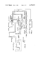
- FIG. 1 is a schematic elevational view depicting the system for measuring the charge distribution of toner particles
- FIG. 2 is a schematic elevational view illustrating the charge spectrograph used in the FIG. 1 system
- FIG. 3 is a fragmentary sectional view showing the inlet tube of the FIG. 2 spectrograph
- FIG. 4 is a fragmentary elevational view, partially in section, depicting the upper portion of the FIG. 2 spectrograph;
- FIG. 5 is a diagram of the circuitry associated with the electrodes used in the FIG. 2 spectrograph
- FIG. 6 is a fragmentary elevational view showing toner particles being introduced into the FIG. 2 charge spectrograph
- FIG. 7 is a plan view of the device used to support developer material as toner particles are being placed in the FIG. 2 spectrograph;
- FIG. 8 is an elevational view, partially in section, showing the needle for directing a stream of air onto the developer material to separate the toner particles therefrom so that the toner particles descend into the FIG. 2 spectrograph;
- FIG. 9 is a block diagram of the system for analyzing the toner particle distribution produced in the FIG. 2 spectrograph.
- FIG. 10 is a computer generated histogram of a typical toner particle distribution.
- FIG. 1 schematically depicts the various components of the system for measuring the charge distribution of toner particles. It will become evident from the following discussion that the system described hereinafter is equally well suited for use in measuring the charge distribution of a wide variety of particles and is not necessarily limited in its application to the particular embodiment shown herein.
- the system includes a charge spectrograph, indicated generally by the reference numeral 10.
- Air needle 12 directs an air stream onto developer material 14 so as to separate the toner particles from the carrier granules thereof.
- the toner particles descend into charge spectrograph 10.
- the system is activated by turning on air pump 16.
- the system operates at a fixed air velocity of about one meter per second.
- the main air flow passes through conduit 18.
- the air flow from the inlet air guard passes through conduit 20, and the exhaust air flow passes through conduit 22.
- Valve 24, which is a ball type of valve sets the flow at one meter per second. This flow rate is measured by flow meter 26.
- Manometer 28 is coupled to interior chamber of charge spectrograph 10 so as to monitor the pressure thereof.
- This pressure is determined by the design of interior chamber of spectrograph 10.
- the pressure sets the air velocity level in the interior of spectrograph 10.
- the interior chamber pressure ranges from about 51/2 inches to about 61/2 inches of water.
- Valve 30 controls the flow to the inlet air guard. The flow is regulated to be about 180 cubic centimeters per minute.
- Solenoid valve 32 gates the air flow from the air guard on and off with the main spectrograph switch.
- the air line for the air guard flow includes a prefilter 34, a regulator 35 which sets the line pressure at 10 psi, and a 5 micron filter 38.
- Flow meter 40 measures the exhaust air flow from the inlet portion of spectrograph 10.
- Valve 42 sets this air flow to be about six liters per minute.
- Power supply 44 is coupled to the electrodes of spectrograph 10 and generates an electrical field having an upper limit of 1000 volts per centimeter. Most samples have a field setting of between 20 and 200 volts per centimeter. Power supply 44 is capable of producing from 0 to 6000 volts D.C..
- Charge spectrograph 10 includes a housing 46 defining an interior chamber of 48.
- the top section of spectrograph 10 includes inlet tube 50.
- An annular fine glass frit 52 is positioned about the input portion of tube 50 which places a coaxial air sheath around the entering sample of toner particles.
- Tube 50 is smooth and made of a drawn-down glass tube. It has a tin oxide coated on its inner surface to provide electrical shielding at a controlled level of potential.
- the main air flow enters through a nylon screen 54 over an input port. After entering the interior chamber 48 of housing 46, the main air flow passes through a nylon mesh screen 56 and then through a honeycomb flow straightener 58.
- the main air flow then passes through nylon screens 60 and 62 which have substantially equally sized apertures therein. These nylon screens flatten the air velocity profile so that the velocity of the air flowing across interior chamber 48 of housing 46 is substantially uniform.
- the conductances of the inlet tube and main air screens and meshes are adjusted so that velocity matching occurs at the outlet of tube 50.
- the air flow in the interior chamber 48 of housing 48 is substantially at the same velocity as that of the air flow exiting tube 50.
- the velocity of the air is approximately 100 centimeters per second.
- the deflection portion of interior chamber 48 includes electrical field shaping electrodes 55 disposed on the inner walls of housing 46. These electrodes are made from a conductive tin oxide coating on the glass wall of housing 46.
- the electrodes are a series of substantially rectangular members with their longitudinal axis being substantially parallel to the longitudinal axis of spectrograph 10. Each electrode is set at a different potential so as to produce a uniform field in the interior chamber 48 of housing 46.
- the outlet portion of tube 50 is positioned within side wall electrode structure 56 and tube 50 is an electrical shield held at ground potential.
- the base section contains an air permeable grid electrode structure 61 which provides a very smooth potential ramp directly beneath filter 63. It is necessary to have a very smooth ramp in order to avoid distorting the pattern of the particles deposited on filter 63.
- Electrode 61 is formed from a plurality of substantially equally spaced wires forming one axis of a grid and substantially equally spaced nylon threads forming the other axis of the grid.
- a plurality of dropping resistors couple the metal wires to power supply 44.
- Both side wall electrodes 55 and bottom electrodes 61 are driven from a common, ground-center power supply 44. This arrangement generates an electrical field of up to 1000 volts per centimeter.
- Resistors of bottom electrode 61 are formed by coating one edge of the screen with a slurry of colloidal graphite and molyblenium disulfide to form painted on resistors having a resistance of about 20 meg/ohms end to end.
- Base electrode 61 is supported by a coarse glass frit filter and air field flattener 65. Glass frit filter 65 is mounted on base 64 which is coupled to conduit 18. As toner particles are collected on filter 63, the fields above the toner particles tend to repel subsequent toner particles.
- filter 63 In order to minimize the range of these fields above filter 63, it is necessary to make filters 63 slightly conductive. The conductivity must be held sufficiently low so that the filter does not electrically short circuit grid 61. Filter 63 is coated with an electrically conductive liquid, and dried. Thus, in operation, the toner particles descend through inlet tube 50 into the interior 48 of housing 46 where the charge thereon operates in conjunction with the electrical fields established by electrodes 55 and 61 produce a deflection from the nominal vertical. The toner particles are received in filter 63 with the zero input corresponding to the center line of inlet tube 50. Deviations from this zero point or center line are a function of the size and charge of the toner particle.
- inlet tube 50 is designed to minimize the possibility of toner particles hitting the interior walls or from being trapped.
- tube 50 is made preferably from glass having a tin oxide coating thereon which is electrically grounded or at zero potential.
- the inlet portion indicated generally by the reference numeral 66, is approximately 2.0 millimeters in diameter.
- the width of the orifice 68 or the throat region is approximately 0.4 millimeters in diameters.
- the outlet portion, indicated by the reference numeral 70 is approximately 2.2 millimeters in diameter.
- the volume of air flowing through inlet tube 50 ranges from about 210 to about 260 cubic centimeters per minute.
- FIG. 4 The assembly of subcomponents of charge spectrograph 10 located at the entrance thereof is shown in greater detail in FIG. 4.
- the air flow through conduit 20 sets the ratio of sample air to guard air. Air enters air shield 69 through conduit 20 at a volume of about 150 to 200 cubic centimeters per minute. This air flow forms a sheath around the sample air entering inlet tube 50 with the volume thereof controlling the sampling rate. If a residual toner cloud were allowed to dwell in the vicinity of the inlet portion of tube 50, the entering sample would be biased in favor of low charged particles. Thus, the toner cloud must be sampled and the residual particles removed from consideration before this can distort the measurement.
- exhaust duct 71 which sweeps the toner cloud toward the inlet of inlet tube 50.
- the unused particles are trapped on filter 73 which fits tightly around inlet tube 50.
- the developer sample is held about 5 to 10 millimeters above inlet tube 50 and the toner particles stopped therefrom.
- the electrical field across the deflection chamber of the spectrograph varies the sensitivity thereof.
- the proper setting will disperse the trace as far as possible within the limits set by the aperture of washer 72 disposed beneath filter 63 (FIG. 2).
- this field is resettable to an accuracy of approximately 1%.
- the circuitry of power supply 44 is shown in FIG. 5.
- a stable adjustable power supply and digital voltmeter are connected to the spectrograph as shown in FIG. 5.
- painted bottom resistors 74 and 76 are connected to power supply 75. Resistors 74 and 76 have a resistance of approximately 10 megohms. Similarly resistors 78 and 80 are connected to side wall electrodes 56. Resistors 78 and 80 have a resistance of about 3 megohms. Digital voltmeter 82 is coupled by a switch 84 to power supply 75 through resistors 86, 88, 90 and 92. Switch 84 provides a balance check of power supply 75.
- resistor 86 has a resistance of 330 kilohms, resistor 88, a resistance of 660 kilohms, resistor 90, a resistance of 660 kilohms and resistor 92 a resistance of 330 kilohms, so that the meter reads directly in volts per centimeter.
- developer sample 14 is held about 5 to 10 millimeters above inlet tube 50. Toner particles are stripped from developer material 14 by air flowing from an air needle 94. Developer material is supported over the edge of the inlet tube and the air needle is directed at the developer material at an angle of about 45° relative to the axis of tube 50. Developer material 14 is attracted magnetically to support 96 which is mounted on a magnetic chuck 98.
- support 96 includes a one millimeter diameter steel wire 100 cemented to a horseshoe magnet 102.
- Steel wire 100 is cemented to magnet 102.
- the wire is bent so that the poles formed therein are separated from one another and extend away from magnet 102. Developer material is then held between the poles of steel wire 100 in the vicinity of opening 104.
- air needle 94 in greater detail.
- a pyrex glass tube 106 is drawn to form a fine nozzle for the air jet.
- Cement 107 secures tube 106 to the interior of stainless steel tube 108.
- a fine, high velocity air stream is then directed at the developer material supported on support 96. Toner particles are completely stripped from the carrier granules of the developer material where the air directly impinges thereon.
- Air is supplied to air needle 94 at a pressure ranging from 15 to 20 psi and a flow of about 5 cubic centimeters per second for a 100 micron opening in tube 106.
- image analyzer 109 is an Omnicon manufactured by Bausch and Lomb.
- Image analyzer 109 includes a microscrope 110 having a stage for supporting filter 63 thereon and computer 112. Activation of computer 112 starts an interactive program which controls microscrope 110 and produces an histogram of particle charge distribution.
- computer 112 is a Nova-2 computer.
- Filter 63 has a pair of zero spots which are made by sampling toner with power supply 75 set at zero volts. These are used as references for the image analysis. The trace is then scanned in a square wave pattern. Data for the total sample is initially printed.
- This data includes the size distribution of the entire sample independent of charge.
- a computed triboelectric characteristic of the entire sample and the average charge are also printed.
- the charge/diameter for each particle is known, in as much as displacement is known, the diameter of each particle is measured and the charge thereof may be readily determined.
- the charge distribution for each size particle is printed.
- a typical histogram is shown in FIG. 10.
- the computer terminal produces a histogram of count versus charge divided by diameter rather than charge alone as printed for each size particle. Since each size corresponds to a narrow range in sizes, the histograms can be directly scaled to charge.
- the basic program for controlling computer 112 is listed in the Appendix.
- a system for measuring the charge distribution of toner particles represents a significant tool for determining satisfactory or unsatisfactory developer material.
- developer material may be inspected on a continuous or sampling basis to insure that the material utilized in the electrophotographic printing machine has the requisite charge properties.
- the apparatus of the present invention produces a printout which provides a measurement of the charge distribution of the toner particles.
Abstract
An apparatus in which the distribution of tones particles is measured as a function of the size and charge thereof. The toner particles pass through a uniform electrical field in the interior chamber of the housing. The resultant deflection from a reference is a function of the size and charge of the particle. A computer driven image analysis system displays a toner charge distribution.
Description
This invention relates generally to electrophotographic printing, and more particularly concerns an improved apparatus for measuring the charge distribution of toner particles used in the developer material of an electrophotographic printing machine.
In electrophotographic printing, a photoconductive member is charged to sensitize the surface thereof. The charged photoconductive member is exposed to a light image of an original document being reproduced. Exposure of the sensitized photoconductive surface discharges the charge selectively. This records an electrostatic latent image on the photoconductive surface corresponding to the informational areas contained within the original document being reproduced. Development of the electrostatic latent image recorded on the photoconductive surface is achieved by bringing a developer material into contact therewith. Typical developer materials comprise the heat settable plastic powder, known in the art as toner particles, which adhere triboelectrically to coarser magnetic carrier granules, such as ferromagnetic granules. The toner particles are selected to have the appropriate charge relative to the electrostatic latent image recorded on the photoconductive surface. When the developer material is brought into contact with the latent image recorded on the photoconductive surface, the greater attractive force thereof causes the toner particles to transfer from the carrier granules to the electrostatic latent image.
Frequently, the variability of the electrical characteristics of the developer material introduces undesirable affects on the resultant copy produced in the printing machine. The charging, and charge stability versus environment and use of the toner particles is a significant problem which has persisted throughout the history of electrophotographic printing. Heretofore, most attempts to study the charge condition of particles was constrained to particles having low charges moving in a low velocity air stream. Generally, the particles had a change ranging from about 10 to about 103 electron charges. However, toner particles generally are highly charged, i.e. in the range of from about 104 to about 105 electron charges.
The following art appears to be relevant as to the different types of devices heretofore used to measure low level charges:
Author: Gillespie et al.
Published: December, 1952
Volume 219, Page 259
Author: Megaw et al.
Published: July 20, 1968
Series B, Page 1682
Author: Liu et al.
Published: June 23, 1969
The pertinent portions of the foregoing articles may be summarized briefly as follows:
Gillespie et al. discloses an instrument for measuring low level particle charges. A thin aerosol of particles surrounded by a sheath of clean air is drawn through a transverse electric field between two microscope slides. A low, laminar air flow is used.
Megaw et al. describes charge measurements made in low charge sub-micron spherical polystyrene particles. The apparatus includes a rectangular box having opposite faces made aluminum covered with copper foil. The aluminum plates are insulated from one another. Filter air flowing at a low rate passes around the aerosol of particles.
Liu et al. discloses a spectrometer for studying the charge on polystyrene latex particles. An aerosol of particles is introduced into a tube by a probe. The probe is positioned an equal distance from a pair of parallel plates connected to a voltage source. A flow of filtered air is introduced to maintain a laminar system. Filter paper is positioned in the tube at the end opposed to the probe. In normal operation, the filter paper is replaced by a device insuring the homogenization of the air exiting the tube. Particle concentration is measured by a meter.
In accordance with the features of the present invention, there is provided an apparatus for measuring the distribution of toner particles as a function of the size and charge thereof. The apparatus includes a housing defining an interior chamber with means being provided for producing a laminar air flow having substantially uniform velocity therein. Means form a substantially uniform electrical field in the interior chamber of the housing with means being provided for introducing the toner particles therein. Means receive the particles that have moved through at least a portion of the electrical field in the interior chamber of the housing. Means scan the toner particles deposited on the receiving means to form a display of the particles as a function of the size and charge thereof.
Other aspects of the present invention will become apparent as the following description proceeds and upon reference to the drawings, in which:
FIG. 1 is a schematic elevational view depicting the system for measuring the charge distribution of toner particles;
FIG. 2 is a schematic elevational view illustrating the charge spectrograph used in the FIG. 1 system;
FIG. 3 is a fragmentary sectional view showing the inlet tube of the FIG. 2 spectrograph;
FIG. 4 is a fragmentary elevational view, partially in section, depicting the upper portion of the FIG. 2 spectrograph;
FIG. 5 is a diagram of the circuitry associated with the electrodes used in the FIG. 2 spectrograph;
FIG. 6 is a fragmentary elevational view showing toner particles being introduced into the FIG. 2 charge spectrograph;
FIG. 7 is a plan view of the device used to support developer material as toner particles are being placed in the FIG. 2 spectrograph;
FIG. 8 is an elevational view, partially in section, showing the needle for directing a stream of air onto the developer material to separate the toner particles therefrom so that the toner particles descend into the FIG. 2 spectrograph;
FIG. 9 is a block diagram of the system for analyzing the toner particle distribution produced in the FIG. 2 spectrograph; and
FIG. 10 is a computer generated histogram of a typical toner particle distribution.
While the present invention will hereinafter be described in connection with a preferred embodiment thereof, it will be understood that it is not intended to limit the invention to that embodiment. On the contrary, it is intended to cover all alternatives, modifications and equivalents as may be included within the spirit and scope of the invention as defined by the appended claims.
For a general understanding of the features of the present invention, reference is made to the drawings. In the drawings, like reference numerals have been used throughout to designate identical elements. FIG. 1 schematically depicts the various components of the system for measuring the charge distribution of toner particles. It will become evident from the following discussion that the system described hereinafter is equally well suited for use in measuring the charge distribution of a wide variety of particles and is not necessarily limited in its application to the particular embodiment shown herein.
As shown in FIG. 1, the system includes a charge spectrograph, indicated generally by the reference numeral 10. Air needle 12 directs an air stream onto developer material 14 so as to separate the toner particles from the carrier granules thereof. The toner particles descend into charge spectrograph 10. The system is activated by turning on air pump 16. The system operates at a fixed air velocity of about one meter per second. The main air flow passes through conduit 18. The air flow from the inlet air guard passes through conduit 20, and the exhaust air flow passes through conduit 22. Valve 24, which is a ball type of valve, sets the flow at one meter per second. This flow rate is measured by flow meter 26. Manometer 28 is coupled to interior chamber of charge spectrograph 10 so as to monitor the pressure thereof. This pressure is determined by the design of interior chamber of spectrograph 10. The pressure sets the air velocity level in the interior of spectrograph 10. By way of example, the interior chamber pressure ranges from about 51/2 inches to about 61/2 inches of water. Valve 30 controls the flow to the inlet air guard. The flow is regulated to be about 180 cubic centimeters per minute. Solenoid valve 32 gates the air flow from the air guard on and off with the main spectrograph switch. The air line for the air guard flow includes a prefilter 34, a regulator 35 which sets the line pressure at 10 psi, and a 5 micron filter 38. Flow meter 40 measures the exhaust air flow from the inlet portion of spectrograph 10. Valve 42 sets this air flow to be about six liters per minute. This setting controls the air volume ratio of sample to clean air surrounding the sample air in the inlet tube. Power supply 44 is coupled to the electrodes of spectrograph 10 and generates an electrical field having an upper limit of 1000 volts per centimeter. Most samples have a field setting of between 20 and 200 volts per centimeter. Power supply 44 is capable of producing from 0 to 6000 volts D.C..
Turning now to FIG. 2, there is shown the detailed structure of charge spectrograph 10. Charge spectrograph 10 includes a housing 46 defining an interior chamber of 48. The top section of spectrograph 10 includes inlet tube 50. An annular fine glass frit 52 is positioned about the input portion of tube 50 which places a coaxial air sheath around the entering sample of toner particles. Tube 50 is smooth and made of a drawn-down glass tube. It has a tin oxide coated on its inner surface to provide electrical shielding at a controlled level of potential. The main air flow enters through a nylon screen 54 over an input port. After entering the interior chamber 48 of housing 46, the main air flow passes through a nylon mesh screen 56 and then through a honeycomb flow straightener 58. The main air flow then passes through nylon screens 60 and 62 which have substantially equally sized apertures therein. These nylon screens flatten the air velocity profile so that the velocity of the air flowing across interior chamber 48 of housing 46 is substantially uniform. The conductances of the inlet tube and main air screens and meshes are adjusted so that velocity matching occurs at the outlet of tube 50. Thus, the air flow in the interior chamber 48 of housing 48 is substantially at the same velocity as that of the air flow exiting tube 50. The velocity of the air is approximately 100 centimeters per second. The deflection portion of interior chamber 48 includes electrical field shaping electrodes 55 disposed on the inner walls of housing 46. These electrodes are made from a conductive tin oxide coating on the glass wall of housing 46. The electrodes are a series of substantially rectangular members with their longitudinal axis being substantially parallel to the longitudinal axis of spectrograph 10. Each electrode is set at a different potential so as to produce a uniform field in the interior chamber 48 of housing 46. The outlet portion of tube 50 is positioned within side wall electrode structure 56 and tube 50 is an electrical shield held at ground potential. The base section contains an air permeable grid electrode structure 61 which provides a very smooth potential ramp directly beneath filter 63. It is necessary to have a very smooth ramp in order to avoid distorting the pattern of the particles deposited on filter 63. Electrode 61 is formed from a plurality of substantially equally spaced wires forming one axis of a grid and substantially equally spaced nylon threads forming the other axis of the grid. A plurality of dropping resistors couple the metal wires to power supply 44. Both side wall electrodes 55 and bottom electrodes 61 are driven from a common, ground-center power supply 44. This arrangement generates an electrical field of up to 1000 volts per centimeter. Resistors of bottom electrode 61 are formed by coating one edge of the screen with a slurry of colloidal graphite and molyblenium disulfide to form painted on resistors having a resistance of about 20 meg/ohms end to end. Base electrode 61 is supported by a coarse glass frit filter and air field flattener 65. Glass frit filter 65 is mounted on base 64 which is coupled to conduit 18. As toner particles are collected on filter 63, the fields above the toner particles tend to repel subsequent toner particles. In order to minimize the range of these fields above filter 63, it is necessary to make filters 63 slightly conductive. The conductivity must be held sufficiently low so that the filter does not electrically short circuit grid 61. Filter 63 is coated with an electrically conductive liquid, and dried. Thus, in operation, the toner particles descend through inlet tube 50 into the interior 48 of housing 46 where the charge thereon operates in conjunction with the electrical fields established by electrodes 55 and 61 produce a deflection from the nominal vertical. The toner particles are received in filter 63 with the zero input corresponding to the center line of inlet tube 50. Deviations from this zero point or center line are a function of the size and charge of the toner particle.
Referring now to FIG. 3, there is shown inlet tube 50 in greater detail. As shown thereat, inlet tube 50 is designed to minimize the possibility of toner particles hitting the interior walls or from being trapped. To shape the required venturi to achieve this, tube 50 is made preferably from glass having a tin oxide coating thereon which is electrically grounded or at zero potential. The inlet portion, indicated generally by the reference numeral 66, is approximately 2.0 millimeters in diameter. The width of the orifice 68 or the throat region is approximately 0.4 millimeters in diameters. The outlet portion, indicated by the reference numeral 70, is approximately 2.2 millimeters in diameter. The volume of air flowing through inlet tube 50 ranges from about 210 to about 260 cubic centimeters per minute.
The assembly of subcomponents of charge spectrograph 10 located at the entrance thereof is shown in greater detail in FIG. 4. Referring now to FIG. 4, the air flow through conduit 20 sets the ratio of sample air to guard air. Air enters air shield 69 through conduit 20 at a volume of about 150 to 200 cubic centimeters per minute. This air flow forms a sheath around the sample air entering inlet tube 50 with the volume thereof controlling the sampling rate. If a residual toner cloud were allowed to dwell in the vicinity of the inlet portion of tube 50, the entering sample would be biased in favor of low charged particles. Thus, the toner cloud must be sampled and the residual particles removed from consideration before this can distort the measurement. This is achieved by exhaust duct 71 which sweeps the toner cloud toward the inlet of inlet tube 50. The unused particles are trapped on filter 73 which fits tightly around inlet tube 50. The developer sample is held about 5 to 10 millimeters above inlet tube 50 and the toner particles stopped therefrom.
The electrical field across the deflection chamber of the spectrograph varies the sensitivity thereof. The proper setting will disperse the trace as far as possible within the limits set by the aperture of washer 72 disposed beneath filter 63 (FIG. 2). To obtain accurate reproducable charge data, this field is resettable to an accuracy of approximately 1%. The circuitry of power supply 44 is shown in FIG. 5. A stable adjustable power supply and digital voltmeter are connected to the spectrograph as shown in FIG. 5.
As shown in FIG. 5, painted bottom resistors 74 and 76 are connected to power supply 75. Resistors 74 and 76 have a resistance of approximately 10 megohms. Similarly resistors 78 and 80 are connected to side wall electrodes 56. Resistors 78 and 80 have a resistance of about 3 megohms. Digital voltmeter 82 is coupled by a switch 84 to power supply 75 through resistors 86, 88, 90 and 92. Switch 84 provides a balance check of power supply 75. Preferably, resistor 86 has a resistance of 330 kilohms, resistor 88, a resistance of 660 kilohms, resistor 90, a resistance of 660 kilohms and resistor 92 a resistance of 330 kilohms, so that the meter reads directly in volts per centimeter.
As shown in FIG. 6, developer sample 14 is held about 5 to 10 millimeters above inlet tube 50. Toner particles are stripped from developer material 14 by air flowing from an air needle 94. Developer material is supported over the edge of the inlet tube and the air needle is directed at the developer material at an angle of about 45° relative to the axis of tube 50. Developer material 14 is attracted magnetically to support 96 which is mounted on a magnetic chuck 98.
As shown in FIG. 7, support 96 includes a one millimeter diameter steel wire 100 cemented to a horseshoe magnet 102. Steel wire 100 is cemented to magnet 102. The wire is bent so that the poles formed therein are separated from one another and extend away from magnet 102. Developer material is then held between the poles of steel wire 100 in the vicinity of opening 104.
Referring now to FIG. 8, there is shown air needle 94 in greater detail. As depicted thereat, a pyrex glass tube 106 is drawn to form a fine nozzle for the air jet. Cement 107 secures tube 106 to the interior of stainless steel tube 108. A fine, high velocity air stream is then directed at the developer material supported on support 96. Toner particles are completely stripped from the carrier granules of the developer material where the air directly impinges thereon. Air is supplied to air needle 94 at a pressure ranging from 15 to 20 psi and a flow of about 5 cubic centimeters per second for a 100 micron opening in tube 106.
Turning now to FIG. 9, after the toner particles have been collected on filter 63, it is mounted on a computer driven image analyzer 109. Preferably, image analyzer 109 is an Omnicon manufactured by Bausch and Lomb. Image analyzer 109 includes a microscrope 110 having a stage for supporting filter 63 thereon and computer 112. Activation of computer 112 starts an interactive program which controls microscrope 110 and produces an histogram of particle charge distribution. Preferably, computer 112 is a Nova-2 computer. Filter 63 has a pair of zero spots which are made by sampling toner with power supply 75 set at zero volts. These are used as references for the image analysis. The trace is then scanned in a square wave pattern. Data for the total sample is initially printed. This data includes the size distribution of the entire sample independent of charge. A computed triboelectric characteristic of the entire sample and the average charge are also printed. The charge/diameter for each particle is known, in as much as displacement is known, the diameter of each particle is measured and the charge thereof may be readily determined. Thus, the charge distribution for each size particle is printed. A typical histogram is shown in FIG. 10.
Referring now to FIG. 10, the computer terminal produces a histogram of count versus charge divided by diameter rather than charge alone as printed for each size particle. Since each size corresponds to a narrow range in sizes, the histograms can be directly scaled to charge.
The basic program for controlling computer 112 is listed in the Appendix.
In recapitulation, it is clear that a system for measuring the charge distribution of toner particles represents a significant tool for determining satisfactory or unsatisfactory developer material. With the utilization of this tool, developer material may be inspected on a continuous or sampling basis to insure that the material utilized in the electrophotographic printing machine has the requisite charge properties. The apparatus of the present invention produces a printout which provides a measurement of the charge distribution of the toner particles.
It is, therefore, evident that there has been provided, in accordance with the present invention, an apparatus for measuring toner particle charge which fully satisfies the aims and advantages herein before set forth. While this invention has been described in conjunction with a specific embodiment thereof, it is evident that many alternatives, modifications and variations will be apparent to those skilled in the art. Accordingly, it is intended to embrace all such alternatives, modifications, and variations as fall within the spirit and broad scope of the appended claims. ##SPC1##
Claims (21)
1. An apparatus for measuring the distribution of highly charged toner particles as a function of the size and charge thereof, including:
a housing defining an interior chamber;
a pump coupled to the interior chamber of said housing to produce a flow of air therethrough;
a plurality of screens disposed in the interior chamber of said housing with each of said plurality of screens being spaced from one another and having substantially uniform apertures therein to produce a substantially uniform pressure drop thereacross so that the air velocity is substantially uniform across the interior chamber of said housing;
means for forming a substantially uniform electrical field in the interior chamber of said housing;
means for introducing the toner particles into the interior chamber of said housing;
means for receiving the particles that have moved through at least a portion of the electrical field in the interior chamber of said housing; and
means for scanning said receiving means to form a display of the particles as a function of the charge and size thereof.
2. An apparatus according to claim 1, wherein said scanning means automatically scans said receiving means and automatically forms a display of the particles.
3. An apparatus according to claim 2, further including means for separating the toner particles from a carrier granule to which one of more of said toner particles are attached before being placed in said introducing means.
4. An apparatus according to claim 1 or 2, or 3 wherein said receiving means includes a filter positioned in the interior chamber of said housing in the region of an air outlet.
5. An apparatus according to claim 4, wherein said forming means includes:
a first electrode disposed about the walls of the chamber of said housing to form a substantially uniform electrical field; and
a second electrode positioned across the bottom of the chamber of said housing in the region of the air outlet.
6. An apparatus according to claim 5, wherein said introducing means includes an inlet tube extending into the interior chamber of said housing, said inlet tube being configured so that air exits therefrom at substantially the same linear velocity as the air flowing in the interior chamber of said housing with the majority of the particles remaining in the inlet air stream without contacting the walls of said tube.
7. An apparatus according to claim 6, wherein said introducing means includes means for generating a flow of air to remove residual particles from the region of the entrance of said inlet tube.
8. An apparatus according to claim 6, wherein said scanning means includes:
a microscope in communication with said filter having the toner particles deposited thereon; and
a computer coupled to said microscope for generating a visual display of the toner particles as a function of the size and charge thereof.
9. An apparatus according to claim 6, further including means for straightening the flow of air in the interior chamber of said housing.
10. An apparatus according to claim 3, in which carrier granules are magnetic, wherein said separating means includes:
a magnetic member for attracting the carrier granules with the toner particles adhering triboelectrically thereto; and
means for directing a narrow, high speed jet of air onto the carrier granules to separate the toner particles therefrom and move them into said inlet tube.
11. A method of measuring the distribution of highly charged toner particles as a function of the size and charge thereof, including the steps of:
producing a laminar air flow having substantially uniform velocity in an interior chamber of a housing by actuating a pump coupled to the interior chamber of the housing and directing the air flow in the chamber of the housing through a plurality of spaced screens having substantially uniform apertures therein to produce a substantially uniform drop thereacross;
forming a substantially uniform electrical field in the interior chamber of the housing;
introducing the toner particles into the interior chamber of the housing;
receiving the toner particles that have moved through at least a portion of the electrical field in the interior chamber of the housing on a support member; and
scanning the support member to form a display of the toner particles deposited on the support member as a function of the charge and size thereof.
12. A method according to claim 11, wherein said step of scanning includes the step of automatically scanning the support member to automatically form a display of the toner particles deposited on the support member as a function of the charge and size thereof.
13. A method according to claim 12, further including the step of separating the toner particles from carrier granules before said step of introducing the toner particles into the interior chamber of the housing.
14. A method according to claims 11, 12 or 13, wherein said step of scanning includes the steps of:
placing the support member with the toner particles deposited thereon in communication with a microscope; and
energizing a computer coupled to the microscope to generate a visual display of the toner particles as a function of the size and charge thereof.
15. A method according to claim 12, wherein said step of introducing includes the step of matching the linear velocity of the air flow in the interior chamber of the housing with the air stream conveying the toner particles therein.
16. A method according to claim 15, wherein said step of introducing includes the step of generating a flow of air to remove residual toner particles from the region of the entrance to the interior chamber of the housing.
17. A method according to claim 16, further including the step of straightening the flow of air in the interior chamber of the housing.
18. An apparatus for measuring the distribution of highly charged toner particles as a function of the size and charge thereof, including:
a housing defining an interior chamber;
means for producing a laminar air flow having substantially uniform velocity of approximately one hundred centimeters per second in the interior chamber of said housing;
means for forming a substantially uniform electrical field in the interior chamber of said housing;
means for introducing the particles into the interior chamber of said housing;
means for receiving the particles that have moved through at least a portion of the electrical field in the interior chamber of said housing; and
means for scanning said receiving means to form a display of the particles as a function of the charge and size thereof.
19. A method of measuring the distribution of highly charged toner particles as a function of the size and charge thereof, including the steps of:
producing a laminar air flow having substantially uniform velocity of approximately one hundred centimeters per second in an interior chamber of a housing;
forming a substantially uniform electrical field in the interior chamber of the housing;
introducing the toner particles into the interior chamber of the housing;
receiving the toner particles that have moved through at least a portion of the electrical field in the interior chamber of the housing on a support member; and
scanning the support member to form a display of the toner particles deposited on the support member as a function of the charge and size thereof.
20. An apparatus for measuring the distribution of highly charged toner particles as a function of the size and charge thereof, including:
a housing defining an interior chamber;
means for producing a laminar air flow having substantially uniform velocity in the interior chamber of said housing;
means for forming a substantially uniform electrical field in the interior chamber of said housing;
means for introducing the particles into the interior chamber of said housing;
means for receiving the particles that have moved through at least a portion of the electrical field in the interior chamber of said housing, said means for receiving positioned at a portion of said housing to receive all particles including those having no or only slight charges; and
means for scanning said receiving means to form a display of the particles as a function of the charge and size thereof.
21. A method of measuring the distribution of highly charged toner particles as a function of the size and charge thereof, including the steps of:
producing a laminar air flow having substantially uniform velocity in an interior chamber of a housing;
forming a substantially uniform electrical field in the interior chamber of the housing;
introducing the toner particles into the interior chamber of the housing;
receiving all toner particles that have moved through at least a portion of the electrical field in the interior chamber of the housing on a support member; and
scanning the support member to form a display of the toner particles deposited on the support member as a function of the charge and size thereof.
Priority Applications (3)
| Application Number | Priority Date | Filing Date | Title |
|---|---|---|---|
| US06/186,981 US4375673A (en) | 1980-09-15 | 1980-09-15 | Charge spectrograph |
| JP56141619A JPS5779958A (en) | 1980-09-15 | 1981-09-08 | Method of and apparatus for measuring charge distribution of toner particles |
| GB8127864A GB2083619B (en) | 1980-09-15 | 1981-09-15 | Charge spectrograph |
Applications Claiming Priority (1)
| Application Number | Priority Date | Filing Date | Title |
|---|---|---|---|
| US06/186,981 US4375673A (en) | 1980-09-15 | 1980-09-15 | Charge spectrograph |
Publications (1)
| Publication Number | Publication Date |
|---|---|
| US4375673A true US4375673A (en) | 1983-03-01 |
Family
ID=22687108
Family Applications (1)
| Application Number | Title | Priority Date | Filing Date |
|---|---|---|---|
| US06/186,981 Expired - Lifetime US4375673A (en) | 1980-09-15 | 1980-09-15 | Charge spectrograph |
Country Status (3)
| Country | Link |
|---|---|
| US (1) | US4375673A (en) |
| JP (1) | JPS5779958A (en) |
| GB (1) | GB2083619B (en) |
Cited By (16)
| Publication number | Priority date | Publication date | Assignee | Title |
|---|---|---|---|---|
| WO1988002482A1 (en) * | 1986-09-30 | 1988-04-07 | Obrien Richard Wyndham | Determination of particle size and electric charge |
| US5245290A (en) * | 1989-02-27 | 1993-09-14 | Matec Applied Sciences, Inc. | Device for determining the size and charge of colloidal particles by measuring electroacoustic effect |
| US5266900A (en) * | 1990-09-21 | 1993-11-30 | Epping Gmbh | Method and apparatus for determining electrical charge characteristics of toner materials |
| US5486900A (en) * | 1993-12-06 | 1996-01-23 | Sharp Kabushiki Kaisha | Measuring device for amount of charge of toner and image forming apparatus having the measuring device |
| DE19542413A1 (en) * | 1994-11-20 | 1996-05-30 | Reinhold H Dr Epping | Particle charge distribution measuring system, e.g. for toner powder |
| US6319647B1 (en) | 2000-03-07 | 2001-11-20 | Xerox Corporation | Toner and developer for magnetic brush development system |
| US6416916B1 (en) | 2000-03-07 | 2002-07-09 | Xerox Corporation | Toner and developer for magnetic brush development system |
| US6553849B1 (en) * | 1998-10-28 | 2003-04-29 | Dillon F. Scofield | Electrodynamic particle size analyzer |
| US6779380B1 (en) * | 1999-01-08 | 2004-08-24 | Wap Reinigungssysteme Gmbh & Co. | Measuring system for the control of residual dust in safety vacuum cleaners |
| US20040229144A1 (en) * | 2002-09-27 | 2004-11-18 | Xerox Corporation | Toners and developers |
| US20050250031A1 (en) * | 2004-05-06 | 2005-11-10 | Xerox Corporation | Black toner and developer |
| US20060283270A1 (en) * | 2005-05-23 | 2006-12-21 | Sharp Kabushiki Kaisha | Sampler for sampling charged particles, and apparatus for measuring charge distribution of the charged particles |
| US20080138731A1 (en) * | 2006-11-21 | 2008-06-12 | Xerox Corporation. | Dual pigment toner compositions |
| EP2175324A2 (en) | 2008-10-10 | 2010-04-14 | Xerox Corporation | Printing system with toner blend |
| DE102009020311A1 (en) | 2009-05-07 | 2010-11-18 | Hydac Filtertechnik Gmbh | Device for determining electrical charge of e.g. purified hydraulic oil in hydraulic plant, has fluid-permeable plate isolatingly fixed in housing at discrete distance to another plate, where capacity of arrangement of plates is measurable |
| DE102012221868A1 (en) | 2011-12-14 | 2013-06-20 | Xerox Corporation | Toner with large strontium titanate particles |
Families Citing this family (6)
| Publication number | Priority date | Publication date | Assignee | Title |
|---|---|---|---|---|
| GB2135463B (en) * | 1983-02-18 | 1986-09-24 | Coal Ind | Dust assessment apparatus and method |
| JPS59214785A (en) * | 1983-05-20 | 1984-12-04 | Konishiroku Photo Ind Co Ltd | Magnetic susceptibility distribution measuring apparatus |
| JPS608758A (en) * | 1983-06-29 | 1985-01-17 | Konishiroku Photo Ind Co Ltd | Measuring device of electric charge distribution of toner particle |
| JP3761724B2 (en) | 1998-10-06 | 2006-03-29 | 富士ゼロックス株式会社 | Image forming method |
| JP4568171B2 (en) * | 2004-07-08 | 2010-10-27 | シャープ株式会社 | Particle charge distribution analyzer |
| DE102006042589A1 (en) * | 2006-09-11 | 2008-04-03 | OCé PRINTING SYSTEMS GMBH | Method and apparatus for determining different properties of toners |
Citations (4)
| Publication number | Priority date | Publication date | Assignee | Title |
|---|---|---|---|---|
| US2537628A (en) * | 1947-09-04 | 1951-01-09 | Firestone Tire & Rubber Co | Histogram computer |
| US3208286A (en) * | 1962-08-02 | 1965-09-28 | Joseph D Richard | Particle size analyzer |
| US3723712A (en) * | 1971-10-12 | 1973-03-27 | Komline Sanderson Eng Corp | Method for agglomeration measuring and control |
| US3944797A (en) * | 1974-08-06 | 1976-03-16 | Coulter Electronics, Inc. | Method and apparatus for determining the correct percentiles of the size distribution of a particulate system |
-
1980
- 1980-09-15 US US06/186,981 patent/US4375673A/en not_active Expired - Lifetime
-
1981
- 1981-09-08 JP JP56141619A patent/JPS5779958A/en active Pending
- 1981-09-15 GB GB8127864A patent/GB2083619B/en not_active Expired
Patent Citations (4)
| Publication number | Priority date | Publication date | Assignee | Title |
|---|---|---|---|---|
| US2537628A (en) * | 1947-09-04 | 1951-01-09 | Firestone Tire & Rubber Co | Histogram computer |
| US3208286A (en) * | 1962-08-02 | 1965-09-28 | Joseph D Richard | Particle size analyzer |
| US3723712A (en) * | 1971-10-12 | 1973-03-27 | Komline Sanderson Eng Corp | Method for agglomeration measuring and control |
| US3944797A (en) * | 1974-08-06 | 1976-03-16 | Coulter Electronics, Inc. | Method and apparatus for determining the correct percentiles of the size distribution of a particulate system |
Non-Patent Citations (3)
| Title |
|---|
| B. Liu et al., "Study of The Electric Charge Carried by Spherical Polystyrene Latex particles, Suspended in Air", C. R. Acadamie of Science of Paris, Series B, Jun. 23, 1969, pp. 1682-1685. |
| T. Gillespie et al., "An Instrument for Determining the Electric Charge Distribution in Aerosols", Canadian Jour. of Chemistry, vol. 30, 12-1952, pp. 1056-1068. |
| W. J. Megan et al., "Electric Mobility of Sub-Micron Particles", Nature, vol. 219, Jul. 20, 1968, pp. 259-261. |
Cited By (24)
| Publication number | Priority date | Publication date | Assignee | Title |
|---|---|---|---|---|
| WO1988002482A1 (en) * | 1986-09-30 | 1988-04-07 | Obrien Richard Wyndham | Determination of particle size and electric charge |
| AU597442B2 (en) * | 1986-09-30 | 1990-05-31 | Colloidal Dynamics Pty. Ltd. | Determination of particle size and electric charge |
| US5245290A (en) * | 1989-02-27 | 1993-09-14 | Matec Applied Sciences, Inc. | Device for determining the size and charge of colloidal particles by measuring electroacoustic effect |
| US5266900A (en) * | 1990-09-21 | 1993-11-30 | Epping Gmbh | Method and apparatus for determining electrical charge characteristics of toner materials |
| US5486900A (en) * | 1993-12-06 | 1996-01-23 | Sharp Kabushiki Kaisha | Measuring device for amount of charge of toner and image forming apparatus having the measuring device |
| DE19542413A1 (en) * | 1994-11-20 | 1996-05-30 | Reinhold H Dr Epping | Particle charge distribution measuring system, e.g. for toner powder |
| US6553849B1 (en) * | 1998-10-28 | 2003-04-29 | Dillon F. Scofield | Electrodynamic particle size analyzer |
| US6779380B1 (en) * | 1999-01-08 | 2004-08-24 | Wap Reinigungssysteme Gmbh & Co. | Measuring system for the control of residual dust in safety vacuum cleaners |
| US6319647B1 (en) | 2000-03-07 | 2001-11-20 | Xerox Corporation | Toner and developer for magnetic brush development system |
| US6416916B1 (en) | 2000-03-07 | 2002-07-09 | Xerox Corporation | Toner and developer for magnetic brush development system |
| US6850725B2 (en) | 2002-09-27 | 2005-02-01 | Xerox Corporation | Toners and developers |
| US20040229144A1 (en) * | 2002-09-27 | 2004-11-18 | Xerox Corporation | Toners and developers |
| US6824942B2 (en) | 2002-09-27 | 2004-11-30 | Xerox Corporation | Toners and developers |
| US20050250031A1 (en) * | 2004-05-06 | 2005-11-10 | Xerox Corporation | Black toner and developer |
| US7157200B2 (en) | 2004-05-06 | 2007-01-02 | Xerox Corporation | Emulsion aggregation black toner and developer with superior image quality |
| US7309556B2 (en) | 2004-05-06 | 2007-12-18 | Xerox Corporation | Black toner and developer |
| US7530279B2 (en) | 2005-05-23 | 2009-05-12 | Sharp Kabushiki Kaisha | Sampler for sampling charged particles, and apparatus for measuring charge distribution of the charged particles |
| US20060283270A1 (en) * | 2005-05-23 | 2006-12-21 | Sharp Kabushiki Kaisha | Sampler for sampling charged particles, and apparatus for measuring charge distribution of the charged particles |
| US20080138731A1 (en) * | 2006-11-21 | 2008-06-12 | Xerox Corporation. | Dual pigment toner compositions |
| US7700252B2 (en) | 2006-11-21 | 2010-04-20 | Xerox Corporation | Dual pigment toner compositions |
| EP2175324A2 (en) | 2008-10-10 | 2010-04-14 | Xerox Corporation | Printing system with toner blend |
| DE102009020311A1 (en) | 2009-05-07 | 2010-11-18 | Hydac Filtertechnik Gmbh | Device for determining electrical charge of e.g. purified hydraulic oil in hydraulic plant, has fluid-permeable plate isolatingly fixed in housing at discrete distance to another plate, where capacity of arrangement of plates is measurable |
| DE102009020311B4 (en) | 2009-05-07 | 2018-09-27 | Hydac Filtertechnik Gmbh | Device for determining the electrical charge of a flowing fluid |
| DE102012221868A1 (en) | 2011-12-14 | 2013-06-20 | Xerox Corporation | Toner with large strontium titanate particles |
Also Published As
| Publication number | Publication date |
|---|---|
| JPS5779958A (en) | 1982-05-19 |
| GB2083619A (en) | 1982-03-24 |
| GB2083619B (en) | 1984-08-08 |
Similar Documents
| Publication | Publication Date | Title |
|---|---|---|
| US4375673A (en) | Charge spectrograph | |
| US6923848B2 (en) | Collecting apparatus of floating dusts in atmosphere | |
| Whitby et al. | Electric aerosol particle counting and size distribution measuring system for the 0.015 to 1 μ size range 1 | |
| US3718029A (en) | Electrostatic mass per unit volume dust monitor | |
| US3526828A (en) | Method and apparatus for measuring particle concentration | |
| US3413545A (en) | Apparatus and method for determining aerosol particle concentration and particle size distribution | |
| CA1256825A (en) | Method and apparatus for sorting particles | |
| US3763428A (en) | Simultaneous measurement of the size distribution of aerosol particles and the number of particles of each size in a flowing gaseous medium | |
| US3520172A (en) | Aerosol sampler | |
| JP2003337087A (en) | Apparatus for collecting suspended particle | |
| US4769609A (en) | Measurement of ultra-fine particles utilizing pulsed corona signals | |
| US3443224A (en) | Measuring probe for determining the distribution of electrostatic charges on the surface of a solid body | |
| Liu et al. | Electrical aerosol analyzer: history, principle, and data reduction | |
| US11047788B2 (en) | Particulate matter sensing device | |
| US2909960A (en) | Method and apparatus for measuring electrical charge on aerosol particles | |
| CN106644856A (en) | Panel device for miniaturized-rapidly measuring fine particle size distribution and measuring method thereof | |
| JP2008104954A (en) | Fine particle classifier | |
| Brown et al. | Theory and measurement of the capture of charged dust particles by electrets | |
| US5266900A (en) | Method and apparatus for determining electrical charge characteristics of toner materials | |
| Hochrainer | Measurement methods for electric charges on aerosols | |
| JP3466416B2 (en) | Differential electric mobility meter | |
| GB2254920A (en) | Measurement of airborne fibres | |
| JP3487464B2 (en) | Blow-off device | |
| Savage et al. | Enhancement of pneumatic nebulization efficiency through application of an electric field | |
| Intra et al. | Development of a fast-response, high-resolution electrical mobility spectrometer |
Legal Events
| Date | Code | Title | Description |
|---|---|---|---|
| AS | Assignment |
Owner name: XEROX CORPORATION, CONNECTICUT Free format text: ASSIGNMENT OF ASSIGNORS INTEREST;ASSIGNORS:LEWIS RICHARD B.;KOEHLER RICHARD F.;CONNORS EDWARD W.;REEL/FRAME:003815/0767 Effective date: 19800912 |
|
| STCF | Information on status: patent grant |
Free format text: PATENTED CASE |