US4385452A - Low voltage sensor for dryer - Google Patents
Low voltage sensor for dryer Download PDFInfo
- Publication number
- US4385452A US4385452A US06/270,130 US27013081A US4385452A US 4385452 A US4385452 A US 4385452A US 27013081 A US27013081 A US 27013081A US 4385452 A US4385452 A US 4385452A
- Authority
- US
- United States
- Prior art keywords
- fabric
- counter
- control
- voltage level
- signal
- Prior art date
- Legal status (The legal status is an assumption and is not a legal conclusion. Google has not performed a legal analysis and makes no representation as to the accuracy of the status listed.)
- Expired - Lifetime
Links
Images


Classifications
-
- G—PHYSICS
- G05—CONTROLLING; REGULATING
- G05D—SYSTEMS FOR CONTROLLING OR REGULATING NON-ELECTRIC VARIABLES
- G05D22/00—Control of humidity
- G05D22/02—Control of humidity characterised by the use of electric means
-
- D—TEXTILES; PAPER
- D06—TREATMENT OF TEXTILES OR THE LIKE; LAUNDERING; FLEXIBLE MATERIALS NOT OTHERWISE PROVIDED FOR
- D06F—LAUNDERING, DRYING, IRONING, PRESSING OR FOLDING TEXTILE ARTICLES
- D06F58/00—Domestic laundry dryers
- D06F58/32—Control of operations performed in domestic laundry dryers
- D06F58/34—Control of operations performed in domestic laundry dryers characterised by the purpose or target of the control
- D06F58/36—Control of operational steps, e.g. for optimisation or improvement of operational steps depending on the condition of the laundry
- D06F58/38—Control of operational steps, e.g. for optimisation or improvement of operational steps depending on the condition of the laundry of drying, e.g. to achieve the target humidity
-
- D—TEXTILES; PAPER
- D06—TREATMENT OF TEXTILES OR THE LIKE; LAUNDERING; FLEXIBLE MATERIALS NOT OTHERWISE PROVIDED FOR
- D06F—LAUNDERING, DRYING, IRONING, PRESSING OR FOLDING TEXTILE ARTICLES
- D06F2103/00—Parameters monitored or detected for the control of domestic laundry washing machines, washer-dryers or laundry dryers
- D06F2103/02—Characteristics of laundry or load
- D06F2103/08—Humidity
- D06F2103/10—Humidity expressed as capacitance or resistance
-
- D—TEXTILES; PAPER
- D06—TREATMENT OF TEXTILES OR THE LIKE; LAUNDERING; FLEXIBLE MATERIALS NOT OTHERWISE PROVIDED FOR
- D06F—LAUNDERING, DRYING, IRONING, PRESSING OR FOLDING TEXTILE ARTICLES
- D06F2103/00—Parameters monitored or detected for the control of domestic laundry washing machines, washer-dryers or laundry dryers
- D06F2103/44—Current or voltage
-
- D—TEXTILES; PAPER
- D06—TREATMENT OF TEXTILES OR THE LIKE; LAUNDERING; FLEXIBLE MATERIALS NOT OTHERWISE PROVIDED FOR
- D06F—LAUNDERING, DRYING, IRONING, PRESSING OR FOLDING TEXTILE ARTICLES
- D06F2105/00—Systems or parameters controlled or affected by the control systems of washing machines, washer-dryers or laundry dryers
- D06F2105/62—Stopping or disabling machine operation
-
- D—TEXTILES; PAPER
- D06—TREATMENT OF TEXTILES OR THE LIKE; LAUNDERING; FLEXIBLE MATERIALS NOT OTHERWISE PROVIDED FOR
- D06F—LAUNDERING, DRYING, IRONING, PRESSING OR FOLDING TEXTILE ARTICLES
- D06F34/00—Details of control systems for washing machines, washer-dryers or laundry dryers
- D06F34/14—Arrangements for detecting or measuring specific parameters
- D06F34/18—Condition of the laundry, e.g. nature or weight
Definitions
- This invention relates to sensing and control techniques for laundry apparatus, and is particularly concerned with methods and apparatus for sensing the moisture content of a clothes load within a dryer and controlling the operation of the clothes dryer on a digital basis.
- U.S. Pat. No. 3,702,030 discloses a high voltage sensor circuit for an integrated circuit control that produces repetitive pulses when the clothes load is drier than a given dryness level for resetting a second counter to prevent the second counter from resetting a first counter.
- the first counter upon reaching a predetermined count, ends the sense portion of the drying cycle.
- Similar circuits are utilized in U.S. Pat. Nos. 3,762,064 and 3,769,716.
- U.S. Pat. No. 3,621,293 discloses the use of a field effect transistor for sensing voltage build up on a capacitor in a dryer control.
- U.S. Pat. No. 4,215,486 discloses a dryer control circuit which utilizes the output of an oscillator, which is frequency dependent on the dryness of the clothes, to feed an amplifier, the output level of which is dependent on the frequency of the oscillator.
- the output of the amplifier is fed to a comparator which compares the amplifier output with a reference voltage and shuts down the dryer when that voltage is reached.
- the present invention provides a means of sensing clothes load moisture in a microcomputer controlled dryer based on the level of moisture retention measured in the clothes load.
- a low voltage sensor circuit senses the degree of dryness of a load of clothes within the dryer and sends either a high or low signal, depending on the sensed dryness, to a microcomputer.
- the microcomputer repetitively reads the input from the sensor circuit at very short intervals. In the preferred embodiment, if it reads a low or wet signal, a pre-selected number of consecutive times, indicating a valid wet signal, the microcomputer resets a search counter. As the clothes load continues to dry, valid wet signals decrease until a sufficient length of time between valid wet signals occurs allowing the search counter to run out. When the search counter has run out, the sensing portion of the process will end and the control circuit will cause the remainder of the selected program to continue.
- FIG. 1 is a perspective view of an automatic dryer embodying the principles of the present invention.
- FIG. 2 is a schematic diagram of a dryer including a dryer control circuit according to the present invention.
- FIG. 3 is a schematic electrical circuit diagram utilized in the present invention.
- FIGS. 4a and 4b comprise a flow chart illustrating the operation of a low voltage sensor control process.
- FIG. 1 there is generally shown an automatic dryer 10 having a cabinet 12 and a control console 14 with controls 16 thereon.
- the controls 16 are generally shown as touch control switches, however, the controls may be of any number of types commonly known in the art.
- the controls provide fabric selection, automatic dry, timed dry, air and touch-up drying cycles. A range of selections are available in the automatic and timed dry cycles.
- a front 18 of the cabinet 12 has door 20 which provides access to the interior of the dryer 10 including a rotatable drum 22.
- door 20 which provides access to the interior of the dryer 10 including a rotatable drum 22.
- a rear stationary bulk-head 24 at the rear of the drum 22 there is an air inlet aperture 26 with a perforate cover plate 27 across the aperture 26 and an air outlet aperture 28 formed by perforations 25 in the bulkhead 24 through which air is circulated by a blower or fan 29 during the drying process.
- a heating element 38 is provided in the air flow path designated by broken line arrow 40 which is selectively energized by a control logic circuit 60 to provide heated air to the interior of the dryer 10 as required.
- Blower 29 is connected in an air flow relationship with the air inlet and outlet apertures so that air is drawn into the drum 22 by way of the aperture 26 after first passing the heating element 38 and is withdrawn from the drum through the aperture 28.
- An electric motor 42 drives the blower 29 and is also provided to rotate the drum 22 by means of a drive pulley 43, a tensioning idler pulley 41, and a belt 44.
- At least one sensor 30 is provide which can be in contact with the clothes load during the drying operation while the drum is rotating.
- the sensor 30 is comprised of two electrodes 32 and 34 which are connected by a pair of conductors 50, 52 to a low voltage moisture sensor circuit 36 as shown in FIG. 2.
- a digital control circuit is generally shown at 48 and includes the sensor circuit 36 which is connected to the sensor electrodes 32, 34, a digital millisecond counter circuit 54 which is driven by a timing crystal 56, a memory storage 58 and the control logic circuit 60 for reading the states of the counter 54 and the stored values in the memory storage 58 for indexing the memory storage 58.
- the control logic circuit 60 includes a plurality of outputs for controlling various machine functions and, accordingly, for controlling the program of the dryer.
- a first output is indicated by the electrical connection line 61 which extends from the control logic circuit 60 to the heating element 38 for controlling the application of heat to the interior of the drum 22.
- a second output is indicated by means of an electrical connection line 62 which extends from the control logic circuit to the electrical drive motor 42 for controlling rotation of the drum 22 and blower 29.
- a third output is indicated by means of an electrical connection line 63 which extends from the control logic circuit 60 to a display circuit 64 which controls a number of indicator lamps behind the panel on the console 14 of the dryer 10 to indicate to the operator which drying functions have been selected and in which portion of the drying cycle the dryer is currently operating.
- Another output is evidenced by the electrical connection line 66 which may be employed, for example, as a master power control lead for disconnecting the circuits from the electrical supply at the termination of the drying program.
- the electrical connections 61, 62, 63 and 66 are in schematic form only, and in practice appropriate interface circuitry such as is well known in the art would be necessary to enable the relatively low level signals developed by the logic circuitry to be used to control the power supply to the machine components.
- the low voltage moisture sensor circuit 30 senses the moisture content in a clothes load represented by the electrical resistance of the clothes and produces a corresponding voltage level signal at an input to a microcomputer.
- the microcomputer determines if the signal is a valid wet signal, and if it is, resets a counter. In the absence of a valid wet signal, the counter reaches a preselected count representative of a given level of dryness of the clothes load and terminates the sensed portion of the drying cycle.
- FIG. 3 details the electrical circuitry utilized in the present invention.
- a transformer 68 is connected to a source of 120 volt alternating current by conductors 70 and 72.
- the alternating current is rectified to direct current by means of diodes 74 and 76.
- a capacitor 78 to protect against voltage spikes, a power supply regulator 82, and a low voltage shut down circuit 84 are provided in a power line conductor 80 to insure a constant voltage level is supplied to a microprocessor or microcomputer 86.
- the timing crystal 56 supplies a timing pulse to the microcomputer along conductors 88, 90.
- a plurality of input switches 92 are connected through resistors 94 and conductors 96 to the microcomputer 86 in order to alert the microcomputer as to certain conditions such as an open door or a filled lint receptacle.
- Output signals on conductors 120, 122 and 124 are sent through drivers 130, 132 and 134 to operate relays 140, 142 and 144 which send appropriate signals along lines 61, 62 and 66 to the heating element, motor and master switch as described above.
- Output signals are also sent on a series of conductors representatively shown by lines 126 and 128 which are strobed through transistors 136 and 138 alternatingly providing closed circuits along a plurality of conductors 129 for various LED's 146 in the display circuit 64.
- the lines 126 and 128 represent any number of lines which are multiplexed to reduce the power requirements of the display circuit.
- Output signals from the microcomputer 86 also are sent on a plurality of conductors 150 through driver amplifiers 152 and on a plurality of conductors 63 to energize the appropriate LED's 146. Output signals are also sent on conductor 154 through drivers 156 to energize an end of cycle alarm 158 at the end of the drying cycle.
- Input switches 160 form a part of the controls 16 which are provided for the operator to make the appropriate selections of the various drying cycle operation options. These input signals are supplied to the microcomputer 86 through a plurality of conductors 162.
- the sensing circuit 36 is comprised of a JFET operational amplifier or comparator 98 whose inputs are a reference voltage on a conductor 105 and a voltage associated with the moisture sensor 30 on a conductor 110.
- a low pass filter capacitor 100 is used on the sensor input to eliminate effects of noise and static.
- a pair of diodes 104 and 102 act as clamps between a ground G and a low voltage source 107, respectively, to prevent excessive voltage excursions in both the positive and negative direction.
- the reference voltage for the positive input of the JFET amplifier 98 on line 105 is the result of the voltage division of low voltage source 107 between resistors 106 and 108. This reference voltage is compared with the voltage on negative input line 110 which is low if wet clothes are in contact with the sensor element 30 and high if dry clothes or no clothes are contacting the element.
- the negative input voltage on line 110 is essentially the voltage division created by a resistor 103 connected to low voltage source 107 and the clothes load resistance across sensor 30, integrated by the capacitor 100 and a resistor 111.
- the capacitor 100 When no clothes or dry clothes are in contact with sensor element 30, the capacitor 100 begins to charge due to the current flow from low voltage source 107 through resistor 103, allowing the voltage on line 110 to increase. When the voltage on line 110 increases above that on line 105, the output signal from the amplifier 98 goes low. If wet clothes come in contact with the sensor 30, the capacitor 100 discharges and the voltage on line 110 drops. This causes the amplifier 98 to produce a high output signal.
- the output signal from the amplifier 98 passes through a voltage divider comprising a pair of resistors 112 and 113, and is inverted by a transistor 114 prior to being input to the microcomputer 86.
- the microcomputer receives a high signal when dry clothes or no clothes bridge the sensor 30 and a low signal when wet clothes bridge the sensor.
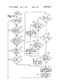
- FIGS. 4a and 4b illustrate the operation of the apparatus of the present invention during an automatic cycle of operation.
- FIGS. 4a and 4b are in functional block diagram form, with the various blocks indicating steps performed in sequence during the performance of the method of the present invention, and also indicating the structure which is employed during the operation of the dryer.
- a preferred embodiment of the present invention employs a microcomputer controller for the performance of the dryness sensing controlling program
- the present invention also contemplates an organization in which each of the blocks illustrated in FIGS. 4a and 4b corresponds to an individual control unit. Control of the operation is passed from control unit to control unit, to execute the program in its proper sequence. The operation proceeds by a sequence of steps.
- the first step in the performance of the automatic operation of the dryness sensing control is by control unit 200 which is periodically energized from a strobe line 202.
- the microcomputer 86 as utilized in the present invention has four strobing circuits under control of a strobing or K-scan unit 205 one of which (202) is devoted to the sensing and time dry portion of the drying cycle.
- the other three strobes control the scanning of the inputs, the selection of the output relays, and the selection of the output lights.
- Control unit 200 inspects the drying cycle selections to determine if the drying cycle is complete. If the drying cycle is complete, then control is passed to unit 204 which performs the various control operations for the cycle selected before returning the strobe line to the K-scan unit 205. If control unit 200 determines that the drying cycle is not complete, then control is passed to unit 206.
- Control unit 206 inspects the cycle selections to determine if the dryer is currently in the anti-wrinkle portion of the cycle. If unit 206 determines that it is, then control is passed again to unit 204 which would perform the control operations for the anti-wrinkle portion of the cycle before returning the strobe line to the K-scan unit 205. If control unit 206 determines that the dryer is not in the anti-wrinkle portion of the cycle, then control is passed to unit 208.
- Control unit 208 inspects the cycle selections to determine if the dryer is in the sensing or timed portion of the cycle. If unit 208 determines that it is not, then control is passed to unit 210 which inspects the cycle selections to determine if the cool down option has been selected. If unit 210 determines that it has, then control is passed again to unit 204 which would perform the control operations for the cool down cycle prior to returning the strobe line to the K-scan unit 205.
- control unit 210 determines that cool down has not been selected, then control is passed to unit 212 which inspects the cycle selections to determine if add-on time is over. If unit 212 determines that it is, then control is passed to unit 204 to perform the various control operations for the cycle selected. If unit 212 determines that the add-on time is not over, then control is passed to a unit 214 which increments a seconds counter in control logic 60 which keeps track of total run time and an A counter in control logic 60 which is used to determine if the clothes load has reached a selected level of dryness. Then control is passed to a unit 216 which stores the total run time.
- control unit 208 determines that the dryer is in the sensing or timed portion of the cycle, then control is passed to unit 218 which inspects the cycle selections to determine if the damp dry dryness level has been selected. If unit 218 determines that damp dry has not been selected, then control is passed through a series of units ending with unit 220 which inspects the cycle selections to determine if the very dry level of dryness had been selected.
- control unit 218 determines that the damp dry level has been selected, control would be passed to unit 222 which inspects counter A to determine if a preselected delay count A for damp dry has been reached.
- the delay count A is a given interval of time in which the sensor 30 has not recorded a valid wet signal. As an example, the delay count A for damp dry could be 15 seconds.
- control unit 222 determines that delay count A for damp dry has been reached, then control is passed to unit 224 which stores total run time to be used in setting the cool down time by unit 204.
- Unit 222 also sets an add-on time in accordance with the procedure disclosed in U.S. Pat. No. 3,762,064 issued to Carl R. Offutt on Oct. 2, 1973 and assigned to the Whirlpool Corporation, the disclosure of which is incorporated herein by reference.
- control unit 224 After control unit 224 has stored the count and set the add-on time, control is passed to the unit 214 which increments the seconds counter and the A counter and then passes control to unit 216 which stores the total run time. If control unit 222 has determined that the delay count A for damp dry has not been reached, then control is passed directly to unit 214.
- control unit 220 determines if the very dry level has been selected. If it has, then control is passed to unit 226 which inspects counter A to determine if delay count A for very dry has been reached. As an example, the delay count A for very dry could be two minutes.
- control unit 226 determines that delay count A for very dry has been reached, then control is passed to unit 228 which stores the total run time and sets the add-on time as described with reference to unit 224. Then control is passed to unit 214 as described above. If control unit 226 determines that delay count A for very dry has not been reached, then control is passed directly to unit 214.
- control unit 220 determines that the very dry level has not been selected. If control has passed from unit 218 through all of the various dryness level control units to unit 220 and control unit 220 determines that the very dry level has not been selected, then control is passed to unit 230 which inspects the cycle selectors to determine which timed dry period has been selected and it inspects the total run time stored by unit 216 to determine if the time period has completely elapsed. If the control unit 230 determines that the time has elapsed, control is then passed to unit 232 which stores the total run time to be used by unit 204 in determining the cool down time and control is then passed to unit 214. If control unit 230 determines that the time period has not completely elapsed, then control is passed directly to unit 214.
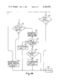
- control unit 214 increments the seconds counter and the A counter and then passes control to unit 216 which stores the total run time. Control is then passed to unit 234. Control unit 234 determines if the sensor 30 is being utilized. If unit 234 determines that the sensor is not being utilized, then control is returned to the K-scan unit 205.
- control unit 234 determines that the sensor is being used, then control is passed to unit 238 which inspects the total run time stored by unit 216 to determine if the dryer has been on for ten minutes. The ten minute initial run time allows the dryer and the clothes load to reach a minimum drying time required for any small clothes loads. If the dryer has been on for less than ten minutes, then control is passed to unit 240 which resets a milliseconds count equal to zero and resets the A counter to zero. Control is then passed to unit 205.
- control unit 238 determines that the dryer has been on for at least ten minutes, then control is passed to unit 242 which increments the milliseconds count by one, representing four milliseconds.
- a millisecond counter is utilized to keep track of the total time accumulated since the last dry signal.
- four strobe lines are utilized and each strobe uses one millisecond, therefore each time the K-scan strobes line 202 and passes through this portion of the program, four milliseconds have elapsed.
- control unit 242 increments the milliseconds by four.
- Control is then passed to unit 244 which inspects the sensor input to determine if there is a dry signal. If there is, then control is passed to unit 246 which resets the milliseconds count to zero and control is passed to unit 205. If control unit 244 determines that there is not a dry signal at the sensor input, then control is passed to unit 248 which inspects the millisecond count to determine if the millisecond count is less than 32, representing 128 milliseconds.
- control unit 205 If the count is below 32, then control is passed to unit 205. However, if the millisecond count is equal to or greater than 32, then control is passed to unit 240 which sets the millisecond count equal to zero and resets the A count to zero. Thus, control unit 248 determines if there have been thirty-two consecutive wet signals. If thirty-two consecutive wet signals have been received, unit 244 determines this to be a valid wet signal and both the millisecond counter and the A counter are reset to zero to restart the search for a given dry period without a wet signal.
- control unit 204 performing the various control operations for the cycle selected. After unit 204 has performed the various control operations, control is passed to the K-scan unit 205.
- a low voltage moisture sensor for a dryer which senses the moisture content in the clothes load and sends an appropriate signal to a microcomputer for use in timing and control functions.
- a first counter is utilized to measure the time since a last valid wet signal has been sent.
- a second millisecond counter is utilized to determine if a valid wet signal has been sensed by the sensor. The first counter is reset each time the second counter determines that a valid wet signal has been sensed. The first counter continues to count, in the absence of a valid wet signal, until a preselected count representing a given level of dryness has been reached.
Abstract
Description
Claims (10)
Priority Applications (2)
| Application Number | Priority Date | Filing Date | Title |
|---|---|---|---|
| US06/270,130 US4385452A (en) | 1981-06-03 | 1981-06-03 | Low voltage sensor for dryer |
| CA000393378A CA1173132A (en) | 1981-06-03 | 1981-12-30 | Low voltage sensor for dryer |
Applications Claiming Priority (1)
| Application Number | Priority Date | Filing Date | Title |
|---|---|---|---|
| US06/270,130 US4385452A (en) | 1981-06-03 | 1981-06-03 | Low voltage sensor for dryer |
Publications (1)
| Publication Number | Publication Date |
|---|---|
| US4385452A true US4385452A (en) | 1983-05-31 |
Family
ID=23030028
Family Applications (1)
| Application Number | Title | Priority Date | Filing Date |
|---|---|---|---|
| US06/270,130 Expired - Lifetime US4385452A (en) | 1981-06-03 | 1981-06-03 | Low voltage sensor for dryer |
Country Status (2)
| Country | Link |
|---|---|
| US (1) | US4385452A (en) |
| CA (1) | CA1173132A (en) |
Cited By (57)
| Publication number | Priority date | Publication date | Assignee | Title |
|---|---|---|---|---|
| US4422247A (en) * | 1981-06-29 | 1983-12-27 | Whirlpool Corporation | Low voltage sensor for a dryer |
| US4477982A (en) * | 1982-09-27 | 1984-10-23 | The Maytag Company | Microcontroller-based dryer control |
| US4520576A (en) * | 1983-09-06 | 1985-06-04 | Whirlpool Corporation | Conversational voice command control system for home appliance |
| US4546554A (en) * | 1982-11-30 | 1985-10-15 | Cissell Manufacturing Company | Clothes dryer having variable position motor and moisture sensor |
| US4744154A (en) * | 1984-09-11 | 1988-05-17 | Wella Aktiengesellschaft | Measuring and controlling the moisture content of hair |
| EP0326048A2 (en) * | 1988-01-25 | 1989-08-02 | INDUSTRIE ZANUSSI S.p.A. | Device for controlling the drying of laundry in a laundry drier |
| FR2632986A1 (en) * | 1988-06-17 | 1989-12-22 | Ciapem | Microprocessor-controlled clothes drier |
| FR2635539A1 (en) * | 1988-08-19 | 1990-02-23 | Ciapem | Washing machine and/or laundry drier |
| US5006778A (en) * | 1989-08-11 | 1991-04-09 | Whirlpool Corporation | Motor diagnostics and electronic control for a clothers dryer |
| GB2269243A (en) * | 1992-07-29 | 1994-02-02 | Toshiba Kk | Drying machine |
| US5467077A (en) * | 1993-02-25 | 1995-11-14 | Maytag Corporation | Method and means for indicating an appliance condition |
| US5737852A (en) * | 1996-08-05 | 1998-04-14 | White Consolidated Industries, Inc. | Dryness control for clothes dryer |
| US5940986A (en) * | 1997-05-16 | 1999-08-24 | White Consolidated Industries, Inc. | Heat staked moisture sensor electrodes |
| US6020698A (en) * | 1998-10-09 | 2000-02-01 | Whirlpool Corporation | Timer for use with an electronic control in controlling an appliance |
| US6047486A (en) * | 1998-09-03 | 2000-04-11 | Whirlpool Corporation | Control system for a dryer |
| EP1167615A2 (en) * | 2000-06-30 | 2002-01-02 | Whirlpool Corporation | Fuzzy logic control for an electric clothes dryer |
| US6519871B2 (en) | 2001-05-25 | 2003-02-18 | Maytag Corporation | Self programming clothes dryer system |
| US6560466B1 (en) * | 1998-09-15 | 2003-05-06 | Agere Systems, Inc. | Auditory feedback control through user detection |
| US20040168343A1 (en) * | 2002-11-26 | 2004-09-02 | Park Sang Ho | Laundry drier |
| US20040200093A1 (en) * | 2000-05-02 | 2004-10-14 | Wunderlin William Joseph | System and method for controlling a dryer appliance |
| US20040211083A1 (en) * | 2003-04-28 | 2004-10-28 | Park Soo Won | Sensor assembly for automatic dryer |
| US20040261287A1 (en) * | 2003-06-24 | 2004-12-30 | Zupancic Joel K. | System and method for controlling the operating parameters of a setting system |
| US20050091876A1 (en) * | 2003-11-03 | 2005-05-05 | Yang Jae S. | Dryer control method and apparatus using the same |
| US20050091875A1 (en) * | 2003-11-03 | 2005-05-05 | Kim Sang D. | Dryer control method and dryer using the same |
| US20050097773A1 (en) * | 2003-11-07 | 2005-05-12 | Maytag Corporation | Method and apparatus for appliance display |
| US20050132599A1 (en) * | 2003-12-18 | 2005-06-23 | Lg Electronics Inc. | Drying method of washing machine and apparatus thereof |
| US20050202999A1 (en) * | 2004-02-27 | 2005-09-15 | Woo Rick A. | Multiple use fabric conditioning block with indentations |
| US20050252028A1 (en) * | 2004-05-13 | 2005-11-17 | Lg Electronics Inc. | Control method of clothes dryer and apparatus thereof |
| EP1657352A1 (en) * | 2004-11-11 | 2006-05-17 | Samsung Electronics Co., Ltd. | Clothing drying machine and method for sensing dryness level using the same |
| US20060218976A1 (en) * | 2005-03-31 | 2006-10-05 | Lg Electronics Inc. | Drying machine |
| US20060230632A1 (en) * | 2005-04-18 | 2006-10-19 | Maytag Corporation | Dryness sensor for clothes dryer |
| US20060242858A1 (en) * | 2005-04-28 | 2006-11-02 | Mabe Canada Inc. | Apparatus and method for controlling a clothes dryer |
| EP1736761A1 (en) * | 2005-06-24 | 2006-12-27 | Electrolux Home Products Corporation N.V. | Humidity sensor and dryer with a humidity sensor |
| US20070144033A1 (en) * | 2003-06-24 | 2007-06-28 | Kocjan Tomasz P | System and method for operating a drying unit |
| US20070209228A1 (en) * | 2003-12-23 | 2007-09-13 | Bsh Bosch Und Siemens Hausgerate Gmbh | Method And Device For Drying Clothes |
| US20070227030A1 (en) * | 2006-03-31 | 2007-10-04 | Lg Electronics Inc. | Dryer and method for controlling the same |
| US20080034611A1 (en) * | 2005-06-23 | 2008-02-14 | Whirlpool Corporation | Automatic clothes dryer |
| US20080072450A1 (en) * | 2006-09-06 | 2008-03-27 | Kim Yang-Hwan | Clogging detecting system for dryer |
| US20080072448A1 (en) * | 2006-09-25 | 2008-03-27 | Ecolab Inc. | Determination of dryness of textiles in a dryer |
| US20080078100A1 (en) * | 2006-09-06 | 2008-04-03 | Ju-Hyun Kim | Dryer with clogging detecting function |
| US20090126422A1 (en) * | 2007-11-16 | 2009-05-21 | Jong Seok Kim | Fabric treating machine |
| US20100011614A1 (en) * | 2006-04-14 | 2010-01-21 | Lg Electronics Inc. | Dryer and method for controlling of the same |
| US20100064546A1 (en) * | 2006-04-14 | 2010-03-18 | Lg Electronics Inc. | Dryer and controlling method thereof |
| CN102031684A (en) * | 2010-12-16 | 2011-04-27 | 广东盈科电子有限公司 | Clothes humidity detection device for clothes dryer |
| US7975400B2 (en) * | 2002-12-20 | 2011-07-12 | Bsh Bosch Und Siemens Hausgeraete Gmbh | Device for determining the conductance of laundry, dryers and method for preventing deposits on electrodes |
| US20130192081A1 (en) * | 2012-01-30 | 2013-08-01 | Alliance Laundry Systems Llc | Laundry moisture sensing, control, diagnostic and method |
| US8578627B2 (en) | 2010-10-21 | 2013-11-12 | Whirlpool Corporation | Method and apparatus for moisture sensor noise immunity |
| US20140115916A1 (en) * | 2011-06-22 | 2014-05-01 | Electrolux Home Products Corporation N.V. | Method of Controlling a Rotatable-Drum Laundry Dryer and a Rotatable-Drum Laundry Dryer Implementing the Method |
| US8782922B2 (en) | 2010-11-24 | 2014-07-22 | Ecolab Usa Inc. | Dryer monitoring |
| US9206543B2 (en) | 2011-10-14 | 2015-12-08 | Ecolab Usa Inc. | Dryer monitoring |
| US9939198B2 (en) | 2015-06-26 | 2018-04-10 | M&R Printing Equipment, Inc. | Dryer conveyor belt tracking system |
| US9951991B2 (en) | 2015-08-31 | 2018-04-24 | M&R Printing Equipment, Inc. | System and method for dynamically adjusting dryer belt speed |
| CN108631285A (en) * | 2017-03-25 | 2018-10-09 | 青岛海尔洗衣机有限公司 | Dryer electrostatic discharge protective circuit and dryer |
| US10113795B2 (en) | 2015-06-26 | 2018-10-30 | M&R Printing Equipment, Inc. | Dryer conveyor belt tracking system |
| US10808351B1 (en) * | 2017-01-06 | 2020-10-20 | United Services Automobile Association (Usaa) | Appliance monitoring sensors |
| US20210040676A1 (en) * | 2018-03-07 | 2021-02-11 | Electrolux Appliances Aktiebolag | Appliance with capacitive humidity sensor |
| EP3879023A1 (en) | 2020-03-10 | 2021-09-15 | BSH Hausgeräte GmbH | Method for detecting a load of a rotating drum in a laundry treatment machine, and corresponding laundry treatment machine |
Citations (8)
| Publication number | Priority date | Publication date | Assignee | Title |
|---|---|---|---|---|
| US3460267A (en) * | 1967-04-20 | 1969-08-12 | Ranco Inc | Dryer control |
| US3621293A (en) * | 1970-03-09 | 1971-11-16 | Gen Electric | Electronic dryer control |
| US3702030A (en) * | 1971-03-29 | 1972-11-07 | Whirlpool Co | Digital dryer control circuit |
| US3762064A (en) * | 1971-11-12 | 1973-10-02 | Whirlpool Co | Timer with cycle and time dependent runout for dryer |
| US3769716A (en) * | 1971-11-12 | 1973-11-06 | Whirlpool Co | Variable timer runout control for dryer |
| US4197866A (en) * | 1977-09-19 | 1980-04-15 | Neal Jerry D | Soil moisture sampler and controller |
| US4215486A (en) * | 1977-11-16 | 1980-08-05 | Bosch-Siemens Hausgerate Gmbh | Circuit for controlling a dryer-program switching device |
| GB2068099A (en) * | 1980-01-28 | 1981-08-05 | Philips Electronic Associated | Control device for laundry drier |
-
1981
- 1981-06-03 US US06/270,130 patent/US4385452A/en not_active Expired - Lifetime
- 1981-12-30 CA CA000393378A patent/CA1173132A/en not_active Expired
Patent Citations (8)
| Publication number | Priority date | Publication date | Assignee | Title |
|---|---|---|---|---|
| US3460267A (en) * | 1967-04-20 | 1969-08-12 | Ranco Inc | Dryer control |
| US3621293A (en) * | 1970-03-09 | 1971-11-16 | Gen Electric | Electronic dryer control |
| US3702030A (en) * | 1971-03-29 | 1972-11-07 | Whirlpool Co | Digital dryer control circuit |
| US3762064A (en) * | 1971-11-12 | 1973-10-02 | Whirlpool Co | Timer with cycle and time dependent runout for dryer |
| US3769716A (en) * | 1971-11-12 | 1973-11-06 | Whirlpool Co | Variable timer runout control for dryer |
| US4197866A (en) * | 1977-09-19 | 1980-04-15 | Neal Jerry D | Soil moisture sampler and controller |
| US4215486A (en) * | 1977-11-16 | 1980-08-05 | Bosch-Siemens Hausgerate Gmbh | Circuit for controlling a dryer-program switching device |
| GB2068099A (en) * | 1980-01-28 | 1981-08-05 | Philips Electronic Associated | Control device for laundry drier |
Cited By (110)
| Publication number | Priority date | Publication date | Assignee | Title |
|---|---|---|---|---|
| US4422247A (en) * | 1981-06-29 | 1983-12-27 | Whirlpool Corporation | Low voltage sensor for a dryer |
| US4477982A (en) * | 1982-09-27 | 1984-10-23 | The Maytag Company | Microcontroller-based dryer control |
| US4546554A (en) * | 1982-11-30 | 1985-10-15 | Cissell Manufacturing Company | Clothes dryer having variable position motor and moisture sensor |
| US4520576A (en) * | 1983-09-06 | 1985-06-04 | Whirlpool Corporation | Conversational voice command control system for home appliance |
| US4744154A (en) * | 1984-09-11 | 1988-05-17 | Wella Aktiengesellschaft | Measuring and controlling the moisture content of hair |
| EP0326048A3 (en) * | 1988-01-25 | 1990-05-30 | Industrie Zanussi S.P.A. | Device for controlling the drying of laundry in a laundry drier |
| EP0326048A2 (en) * | 1988-01-25 | 1989-08-02 | INDUSTRIE ZANUSSI S.p.A. | Device for controlling the drying of laundry in a laundry drier |
| FR2632986A1 (en) * | 1988-06-17 | 1989-12-22 | Ciapem | Microprocessor-controlled clothes drier |
| FR2635539A1 (en) * | 1988-08-19 | 1990-02-23 | Ciapem | Washing machine and/or laundry drier |
| US5006778A (en) * | 1989-08-11 | 1991-04-09 | Whirlpool Corporation | Motor diagnostics and electronic control for a clothers dryer |
| US5101575A (en) * | 1990-01-02 | 1992-04-07 | Whirlpool Corporation | Heater diagnostics and electronic control for a clothes dryer |
| GB2269243A (en) * | 1992-07-29 | 1994-02-02 | Toshiba Kk | Drying machine |
| US5345694A (en) * | 1992-07-29 | 1994-09-13 | Kabushiki Kaisha Toshiba | Drying machine |
| GB2269243B (en) * | 1992-07-29 | 1996-01-10 | Toshiba Kk | Drying machine |
| US5467077A (en) * | 1993-02-25 | 1995-11-14 | Maytag Corporation | Method and means for indicating an appliance condition |
| US5737852A (en) * | 1996-08-05 | 1998-04-14 | White Consolidated Industries, Inc. | Dryness control for clothes dryer |
| US5940986A (en) * | 1997-05-16 | 1999-08-24 | White Consolidated Industries, Inc. | Heat staked moisture sensor electrodes |
| US6047486A (en) * | 1998-09-03 | 2000-04-11 | Whirlpool Corporation | Control system for a dryer |
| US6560466B1 (en) * | 1998-09-15 | 2003-05-06 | Agere Systems, Inc. | Auditory feedback control through user detection |
| US6020698A (en) * | 1998-10-09 | 2000-02-01 | Whirlpool Corporation | Timer for use with an electronic control in controlling an appliance |
| US20040200093A1 (en) * | 2000-05-02 | 2004-10-14 | Wunderlin William Joseph | System and method for controlling a dryer appliance |
| US20060191161A1 (en) * | 2000-05-02 | 2006-08-31 | Wunderlin William J | System and method for controlling a dryer appliance |
| US7013578B2 (en) | 2000-05-02 | 2006-03-21 | General Electric Company | System and method for controlling a dryer appliance |
| US7478486B2 (en) | 2000-05-02 | 2009-01-20 | General Electric Company | System and method for controlling a dryer appliance |
| EP1167615A2 (en) * | 2000-06-30 | 2002-01-02 | Whirlpool Corporation | Fuzzy logic control for an electric clothes dryer |
| EP1167615A3 (en) * | 2000-06-30 | 2004-01-02 | Whirlpool Corporation | Fuzzy logic control for an electric clothes dryer |
| US6519871B2 (en) | 2001-05-25 | 2003-02-18 | Maytag Corporation | Self programming clothes dryer system |
| US20040168343A1 (en) * | 2002-11-26 | 2004-09-02 | Park Sang Ho | Laundry drier |
| US6928749B2 (en) * | 2002-11-26 | 2005-08-16 | Lg Electronics Inc. | Laundry dryer |
| US7975400B2 (en) * | 2002-12-20 | 2011-07-12 | Bsh Bosch Und Siemens Hausgeraete Gmbh | Device for determining the conductance of laundry, dryers and method for preventing deposits on electrodes |
| US8286369B2 (en) | 2002-12-20 | 2012-10-16 | Bsh Bosch Und Siemens Hausgeraete Gmbh | Device for determining the conductance of laundry, dryers and method for preventing deposits on electrodes |
| US6941678B2 (en) * | 2003-04-28 | 2005-09-13 | Lg Electronics Inc. | Sensor assembly for automatic dryer |
| US20040211083A1 (en) * | 2003-04-28 | 2004-10-28 | Park Soo Won | Sensor assembly for automatic dryer |
| US7347008B2 (en) * | 2003-06-24 | 2008-03-25 | M&R Printing Equipment, Inc. | System and method for controlling the operating parameters of a setting system |
| US20040261287A1 (en) * | 2003-06-24 | 2004-12-30 | Zupancic Joel K. | System and method for controlling the operating parameters of a setting system |
| US20070144033A1 (en) * | 2003-06-24 | 2007-06-28 | Kocjan Tomasz P | System and method for operating a drying unit |
| US20050091875A1 (en) * | 2003-11-03 | 2005-05-05 | Kim Sang D. | Dryer control method and dryer using the same |
| US7448145B2 (en) | 2003-11-03 | 2008-11-11 | Lg Electronics Inc. | Dryer control method and dryer using the same |
| US20050091876A1 (en) * | 2003-11-03 | 2005-05-05 | Yang Jae S. | Dryer control method and apparatus using the same |
| US7171763B2 (en) * | 2003-11-03 | 2007-02-06 | Lg Electronics Inc. | Dryer control method and dryer using the same |
| US20070033829A1 (en) * | 2003-11-03 | 2007-02-15 | Kim Sang D | Dryer control method and dryer using the same |
| US6931760B2 (en) * | 2003-11-03 | 2005-08-23 | Lg Electronics Inc. | Dryer control method and apparatus using the same |
| US20050097773A1 (en) * | 2003-11-07 | 2005-05-12 | Maytag Corporation | Method and apparatus for appliance display |
| US20050132599A1 (en) * | 2003-12-18 | 2005-06-23 | Lg Electronics Inc. | Drying method of washing machine and apparatus thereof |
| US20070209228A1 (en) * | 2003-12-23 | 2007-09-13 | Bsh Bosch Und Siemens Hausgerate Gmbh | Method And Device For Drying Clothes |
| US20050229653A1 (en) * | 2004-02-27 | 2005-10-20 | The Procter & Gamble Company | Fabric conditioning dispenser and methods of use |
| US20050202999A1 (en) * | 2004-02-27 | 2005-09-15 | Woo Rick A. | Multiple use fabric conditioning block with indentations |
| US7977303B2 (en) | 2004-02-27 | 2011-07-12 | The Procter & Gamble Company | Multiple use fabric conditioning block with indentations |
| US7980001B2 (en) * | 2004-02-27 | 2011-07-19 | The Procter & Gamble Company | Fabric conditioning dispenser and methods of use |
| US7127832B2 (en) * | 2004-05-13 | 2006-10-31 | Lg Electronics Inc. | Control method of clothes dryer and apparatus thereof |
| US20050252028A1 (en) * | 2004-05-13 | 2005-11-17 | Lg Electronics Inc. | Control method of clothes dryer and apparatus thereof |
| CN100445459C (en) * | 2004-05-13 | 2008-12-24 | Lg电子株式会社 | Control method of clothes dryer and apparatus thereof |
| KR101052778B1 (en) | 2004-11-11 | 2011-08-01 | 삼성전자주식회사 | Clothes dryer and dryness detection method |
| US7353624B2 (en) | 2004-11-11 | 2008-04-08 | Samsung Electronics Co., Ltd. | Clothing drying machine and method for sensing dryness level using the same |
| EP1657352A1 (en) * | 2004-11-11 | 2006-05-17 | Samsung Electronics Co., Ltd. | Clothing drying machine and method for sensing dryness level using the same |
| US7506458B2 (en) * | 2005-03-31 | 2009-03-24 | Lg Electronics Inc. | Drying machine |
| US20060218976A1 (en) * | 2005-03-31 | 2006-10-05 | Lg Electronics Inc. | Drying machine |
| US20060230632A1 (en) * | 2005-04-18 | 2006-10-19 | Maytag Corporation | Dryness sensor for clothes dryer |
| US7475495B2 (en) | 2005-04-18 | 2009-01-13 | Maytag Corporation | Dryness sensor for clothes dryer |
| US20080052951A1 (en) * | 2005-04-28 | 2008-03-06 | Mabe Canada Inc. | Apparatus and method for controlling a clothes dryer |
| US7971371B2 (en) * | 2005-04-28 | 2011-07-05 | Mabe Canada Inc. | Apparatus and method for controlling a clothes dryer |
| US20060242858A1 (en) * | 2005-04-28 | 2006-11-02 | Mabe Canada Inc. | Apparatus and method for controlling a clothes dryer |
| US20080052954A1 (en) * | 2005-04-28 | 2008-03-06 | Mabe Canada Inc. | Apparatus and method for controlling a clothes dryer |
| US7322126B2 (en) | 2005-04-28 | 2008-01-29 | Mabe Canada Inc. | Apparatus and method for controlling a clothes dryer |
| US7975401B2 (en) | 2005-04-28 | 2011-07-12 | Mabe Canada Inc. | Apparatus and method for controlling a clothes dryer |
| US8015726B2 (en) * | 2005-06-23 | 2011-09-13 | Whirlpool Corporation | Automatic clothes dryer |
| US20080034611A1 (en) * | 2005-06-23 | 2008-02-14 | Whirlpool Corporation | Automatic clothes dryer |
| US7913418B2 (en) * | 2005-06-23 | 2011-03-29 | Whirlpool Corporation | Automatic clothes dryer |
| EP1736761A1 (en) * | 2005-06-24 | 2006-12-27 | Electrolux Home Products Corporation N.V. | Humidity sensor and dryer with a humidity sensor |
| EP1744152A1 (en) * | 2005-06-24 | 2007-01-17 | Electrolux Home Products N.V. | Humidity sensor and dryer with a humidity sensor |
| US9267229B2 (en) * | 2006-03-31 | 2016-02-23 | Lg Electronics Inc. | Dryer and method for controlling the same |
| US20070227030A1 (en) * | 2006-03-31 | 2007-10-04 | Lg Electronics Inc. | Dryer and method for controlling the same |
| US9657433B2 (en) * | 2006-04-14 | 2017-05-23 | Lg Electronics Inc. | Dryer and controlling method thereof |
| US8919010B2 (en) * | 2006-04-14 | 2014-12-30 | Lg Electronics Inc. | Dryer and method for controlling of the same |
| US20100064546A1 (en) * | 2006-04-14 | 2010-03-18 | Lg Electronics Inc. | Dryer and controlling method thereof |
| US20100011614A1 (en) * | 2006-04-14 | 2010-01-21 | Lg Electronics Inc. | Dryer and method for controlling of the same |
| US20080072450A1 (en) * | 2006-09-06 | 2008-03-27 | Kim Yang-Hwan | Clogging detecting system for dryer |
| US20080078100A1 (en) * | 2006-09-06 | 2008-04-03 | Ju-Hyun Kim | Dryer with clogging detecting function |
| US8387272B2 (en) * | 2006-09-06 | 2013-03-05 | Lg Electronics Inc. | Clogging detecting system for dryer |
| US7926201B2 (en) | 2006-09-06 | 2011-04-19 | Lg Electronics Inc. | Dryer with clogging detecting function |
| US20080072448A1 (en) * | 2006-09-25 | 2008-03-27 | Ecolab Inc. | Determination of dryness of textiles in a dryer |
| US9249539B2 (en) | 2006-09-25 | 2016-02-02 | Ecolab Inc. | Determination of dryness of textiles in a dryer |
| US20090126422A1 (en) * | 2007-11-16 | 2009-05-21 | Jong Seok Kim | Fabric treating machine |
| US8215133B2 (en) * | 2007-11-16 | 2012-07-10 | Lg Electronics Inc. | Fabric treating machine |
| US8578627B2 (en) | 2010-10-21 | 2013-11-12 | Whirlpool Corporation | Method and apparatus for moisture sensor noise immunity |
| US8782922B2 (en) | 2010-11-24 | 2014-07-22 | Ecolab Usa Inc. | Dryer monitoring |
| CN102031684B (en) * | 2010-12-16 | 2012-06-20 | 广东盈科电子有限公司 | Clothes humidity detection device for clothes dryer |
| CN102031684A (en) * | 2010-12-16 | 2011-04-27 | 广东盈科电子有限公司 | Clothes humidity detection device for clothes dryer |
| US20140115916A1 (en) * | 2011-06-22 | 2014-05-01 | Electrolux Home Products Corporation N.V. | Method of Controlling a Rotatable-Drum Laundry Dryer and a Rotatable-Drum Laundry Dryer Implementing the Method |
| US9206543B2 (en) | 2011-10-14 | 2015-12-08 | Ecolab Usa Inc. | Dryer monitoring |
| US9739007B2 (en) | 2011-10-14 | 2017-08-22 | Ecolab Usa Inc. | Dryer monitoring |
| US9745689B2 (en) | 2011-10-14 | 2017-08-29 | Ecolab Usa Inc. | Dryer monitoring |
| US9850621B2 (en) | 2011-10-14 | 2017-12-26 | Ecolab Usa Inc. | Dryer monitoring |
| US9080282B2 (en) * | 2012-01-30 | 2015-07-14 | Alliance Laundry Systems, Llc | Laundry moisture sensing, control, diagnostic and method |
| US20130192081A1 (en) * | 2012-01-30 | 2013-08-01 | Alliance Laundry Systems Llc | Laundry moisture sensing, control, diagnostic and method |
| US10113795B2 (en) | 2015-06-26 | 2018-10-30 | M&R Printing Equipment, Inc. | Dryer conveyor belt tracking system |
| US10794631B2 (en) | 2015-06-26 | 2020-10-06 | M&R Printing Equipment, Inc. | Dryer conveyor belt tracking system |
| US11740017B2 (en) | 2015-06-26 | 2023-08-29 | M&R Printing Equipment, Inc. | Dryer conveyor belt tracking system |
| US9939198B2 (en) | 2015-06-26 | 2018-04-10 | M&R Printing Equipment, Inc. | Dryer conveyor belt tracking system |
| US11226156B2 (en) | 2015-06-26 | 2022-01-18 | M&R Printing Equipment, Inc. | Dryer conveyor belt tracking system |
| US11156401B2 (en) | 2015-08-31 | 2021-10-26 | M&R Printing Equipment, Inc. | System and method for dynamically adjusting dryer belt speed |
| US9951991B2 (en) | 2015-08-31 | 2018-04-24 | M&R Printing Equipment, Inc. | System and method for dynamically adjusting dryer belt speed |
| US10612850B2 (en) | 2015-08-31 | 2020-04-07 | M&R Printing Equipment, Inc. | System and method for dynamically adjusting dryer belt speed |
| US10808351B1 (en) * | 2017-01-06 | 2020-10-20 | United Services Automobile Association (Usaa) | Appliance monitoring sensors |
| US11505892B1 (en) | 2017-01-06 | 2022-11-22 | United Services Automobile Association (Usaa) | Appliance monitoring sensors |
| CN108631285A (en) * | 2017-03-25 | 2018-10-09 | 青岛海尔洗衣机有限公司 | Dryer electrostatic discharge protective circuit and dryer |
| US20210040676A1 (en) * | 2018-03-07 | 2021-02-11 | Electrolux Appliances Aktiebolag | Appliance with capacitive humidity sensor |
| US11920272B2 (en) * | 2018-03-07 | 2024-03-05 | Electrolux Appliances Aktiebolag | Appliance with capacitive humidity sensor |
| EP3879023A1 (en) | 2020-03-10 | 2021-09-15 | BSH Hausgeräte GmbH | Method for detecting a load of a rotating drum in a laundry treatment machine, and corresponding laundry treatment machine |
| DE102020203000A1 (en) | 2020-03-10 | 2021-09-16 | BSH Hausgeräte GmbH | Method for detecting a loading of a rotating drum in a laundry treatment machine, and corresponding laundry treatment machine |
Also Published As
| Publication number | Publication date |
|---|---|
| CA1173132A (en) | 1984-08-21 |
Similar Documents
| Publication | Publication Date | Title |
|---|---|---|
| US4385452A (en) | Low voltage sensor for dryer | |
| US4422247A (en) | Low voltage sensor for a dryer | |
| US4733479A (en) | Method of controlling an electric clothes dryer including automatic load detection | |
| US3702030A (en) | Digital dryer control circuit | |
| US4649654A (en) | Apparatus for controlling electric clothes dryer and method therefor | |
| US5651194A (en) | Apparatus and method for controlling reversible dryer | |
| US5200684A (en) | Electrical motor monitoring system for a domestic appliance | |
| US4510778A (en) | Control system for a combined appliance | |
| US5101575A (en) | Heater diagnostics and electronic control for a clothes dryer | |
| US5564831A (en) | Method and apparatus for detecting the temperature of an environment | |
| CA1238390A (en) | Control system for clothes dryer | |
| US5166592A (en) | Motor diagnostics and electronic control for a clothes dryer | |
| US5454171A (en) | Clothes dryer automatically determining a period of crease-preventing, intermittent operation | |
| US5193292A (en) | Method and apparatus for automatically terminating the cycle in dryers | |
| US3266167A (en) | Dryer control | |
| US4531307A (en) | Fabric dryer control with cycle interrupt | |
| US20040051540A1 (en) | Condition sensor for a dryer | |
| EP0428846B1 (en) | Tumble drier | |
| GB2034451A (en) | Tumbler dryer | |
| US5075613A (en) | Electrical motor monitoring system for a domestic appliance | |
| US3968421A (en) | Delayed on quick off regulator circuit for appliance control | |
| US3221417A (en) | Moisture sensor control device for a laundry drier | |
| US3266168A (en) | Domestic dryer apparatus | |
| EP0436374A2 (en) | Heater diagnostics and electronic control for a clothes dryer | |
| US3818604A (en) | Termination logic and output suppression for integrated circuit dryer control |
Legal Events
| Date | Code | Title | Description |
|---|---|---|---|
| AS | Assignment |
Owner name: WHIRLPOOL CORPORATION, BENTON HARBOR, MICH. A CORP Free format text: ASSIGNMENT OF ASSIGNORS INTEREST.;ASSIGNORS:DESCHAAF, CLIFFORD L.;GETZ, EDWARD H.;REEL/FRAME:003891/0483 Effective date: 19810522 Owner name: WHIRLPOOL CORPORATION, MICHIGAN Free format text: ASSIGNMENT OF ASSIGNORS INTEREST;ASSIGNORS:DESCHAAF, CLIFFORD L.;GETZ, EDWARD H.;REEL/FRAME:003891/0483 Effective date: 19810522 |
|
| STCF | Information on status: patent grant |
Free format text: PATENTED CASE |
|
| MAFP | Maintenance fee payment |
Free format text: PAYMENT OF MAINTENANCE FEE, 4TH YEAR, PL 96-517 (ORIGINAL EVENT CODE: M170); ENTITY STATUS OF PATENT OWNER: LARGE ENTITY Year of fee payment: 4 |
|
| FEPP | Fee payment procedure |
Free format text: PAYOR NUMBER ASSIGNED (ORIGINAL EVENT CODE: ASPN); ENTITY STATUS OF PATENT OWNER: LARGE ENTITY |
|
| MAFP | Maintenance fee payment |
Free format text: PAYMENT OF MAINTENANCE FEE, 8TH YEAR, PL 96-517 (ORIGINAL EVENT CODE: M171); ENTITY STATUS OF PATENT OWNER: LARGE ENTITY Year of fee payment: 8 |
|
| MAFP | Maintenance fee payment |
Free format text: PAYMENT OF MAINTENANCE FEE, 12TH YEAR, LARGE ENTITY (ORIGINAL EVENT CODE: M185); ENTITY STATUS OF PATENT OWNER: LARGE ENTITY Year of fee payment: 12 |