US4386818A - Polarity indicating connector for battery jumper cables - Google Patents
Polarity indicating connector for battery jumper cables Download PDFInfo
- Publication number
- US4386818A US4386818A US06/257,689 US25768981A US4386818A US 4386818 A US4386818 A US 4386818A US 25768981 A US25768981 A US 25768981A US 4386818 A US4386818 A US 4386818A
- Authority
- US
- United States
- Prior art keywords
- connector
- contacts
- pair
- cables
- battery
- Prior art date
- Legal status (The legal status is an assumption and is not a legal conclusion. Google has not performed a legal analysis and makes no representation as to the accuracy of the status listed.)
- Expired - Lifetime
Links
Images

Classifications
-
- H—ELECTRICITY
- H01—ELECTRIC ELEMENTS
- H01R—ELECTRICALLY-CONDUCTIVE CONNECTIONS; STRUCTURAL ASSOCIATIONS OF A PLURALITY OF MUTUALLY-INSULATED ELECTRICAL CONNECTING ELEMENTS; COUPLING DEVICES; CURRENT COLLECTORS
- H01R13/00—Details of coupling devices of the kinds covered by groups H01R12/70 or H01R24/00 - H01R33/00
- H01R13/66—Structural association with built-in electrical component
- H01R13/717—Structural association with built-in electrical component with built-in light source
- H01R13/7175—Light emitting diodes (LEDs)
-
- H—ELECTRICITY
- H01—ELECTRIC ELEMENTS
- H01R—ELECTRICALLY-CONDUCTIVE CONNECTIONS; STRUCTURAL ASSOCIATIONS OF A PLURALITY OF MUTUALLY-INSULATED ELECTRICAL CONNECTING ELEMENTS; COUPLING DEVICES; CURRENT COLLECTORS
- H01R13/00—Details of coupling devices of the kinds covered by groups H01R12/70 or H01R24/00 - H01R33/00
- H01R13/66—Structural association with built-in electrical component
- H01R13/717—Structural association with built-in electrical component with built-in light source
-
- H—ELECTRICITY
- H01—ELECTRIC ELEMENTS
- H01R—ELECTRICALLY-CONDUCTIVE CONNECTIONS; STRUCTURAL ASSOCIATIONS OF A PLURALITY OF MUTUALLY-INSULATED ELECTRICAL CONNECTING ELEMENTS; COUPLING DEVICES; CURRENT COLLECTORS
- H01R13/00—Details of coupling devices of the kinds covered by groups H01R12/70 or H01R24/00 - H01R33/00
- H01R13/02—Contact members
- H01R13/28—Contacts for sliding cooperation with identically-shaped contact, e.g. for hermaphroditic coupling devices
Definitions
- This invention relates to a connector for battery jumper cables and, more specifically to a connector for battery jumper cables which indicates on each connector half the polarity on each jumper cable prior to making connection.
- Battery jumper cables are well known in the prior art. Such cables normally comprise a pair of cables having a clamp at each end of each cable, the cables being colored differently in order to be able to determine and locate the ends of each individual cable for proper connection to a battery. Cables of this type often do not properly indicate to the user the proper connection to the battery such as in the case of darkness where cable color is not discernible. In addition, the batteries themselves often do not adequately define the polarity of the lugs thereon. It is therefore difficult, if not often impossible to determine the polarity of the various battery cables.
- a set of battery jumper cables is provided with an intermediate hermaphroditic connector, the connector having two portions, each portion being marked to indicate, for each terminal, the polarity thereof, with a further LED device capable of providing two different colors, one when the cable clamps are connected to the proper poles of the battery associated therewith, a different color when the polarities are reversed.
- This procedure is followed for both connector halves. When both connector halves indicate proper battery connection, since the connector halves are hermaphroditic or polarized, the connector cables are then connected together to provide a proper and properly polarized connection. This eliminates the problem inherent in the prior art battery jumper cables as stated hereinabove.
- FIG. 1 is a three dimensional view of a pair of battery jumper cable connectors with the jumper cables connected therein in accordance with the present invention
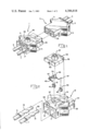
- FIG. 2 is an exploded view of one of the battery jumper cable connector halves of FIG. 1;
- FIG. 3 is a cross-sectional view of a battery jumper cable connector half in accordance with the present invention.
- FIG. 1 there is shown a set of jumper cables 5, 7, 9 and 11 for connecting together a pair of batteries (not shown) with an intermediate connector composed of connector halves 1 and 3.
- the cables from each battery to the associated connector half are shown as 5 and 7 connected in connector half 1 and 9 and 11 connected in connector 3.
- FIGS. 2 and 3 there is provided a detailed showing of one of the connector halves 1 or 3, the description being provided with respect to connector half 1, it being understood that connector half 3 is identical. It is also noted that the connector halves 1 and 3 are hermaphroditic so that they can be connected together in only one orientation.
- the connector half 1 includes an electrically insulating housing 13 which includes a pair of apertures 15 and 17 for receiving contacts 19 and 21 attached to cable 5 and 7.
- the cables 5 and 7 are crimped in the contacts 19 and 21 as better shown in FIG. 3 after the cables 7 and 5 have been partially stripped to provide bare wire 23 at the ends thereof.
- the housing 13 has a hollow interior.
- a spring member 25 which extends into the hollow region has an upwardly extending line 27 which locks the spring into the housing.
- the housing also includes a step portion 33 at its mating end to provide the hermaphroditic feature mentioned hereinabove so that the connector halves 1 and 3 can be connected in only one alignment. This prevents and avoids the possibility of an erroneous connection with improperly placed terminals being connected together.
- the housing 1 further includes an indented upper section 35 having a pair of apertures 37 and 39 therein which extend into the hollow interior region 17.
- a pair of displacement contacts 41 and 43 are positioned in the apertures 37 and 39 respectively.
- the twisted and soldered wires 45 from a resistor 47 and a LED 49 connect these elements in series and lead 75 from resistor 47 is positioned in the groove 51 of the contact 41.
- the other anode terminal of the LED 49 is positioned in the groove 53 of the contact 43.
- the cover 55 has an opening 57 through which the LED 49 is visible, the cover also including a finger 59 which extends into a groove 61 in the housing 1.
- the cover 55 also includes a lip 63 which is lockable under a ledge 77 in the housing (FIG. 3) to secure the components within the connector half 1 in the manner shown in FIG. 3.
- the cover 55 is removable by forcing ledge 77 and lip 63 apart.
- the contact 21 has entered the aperture 17 and rides along a ramp 77 unitl it is locked by the spring 25 which moves into the cup-shaped end 65 of the contact 21 to lock the contact within the connector half.
- the contact 43 is in electrical contact with the spring 25, the latter being electrically conductive and in contact with contact 21 as shown in FIG. 3.
- the other contact 19, shown in FIG. 2, will be in electrical contact with the contact 41.
- a pair of battery jumper cables 5 and 7 is connected to the connector half 1 and a second pair of battery jumper cables 9 and 11 is connected to a second connector half 3 as shown in FIG. 1.
- Each of the connector halves will be marked to indicate the polarity intended at each side of the connector half and the resistor 47 and LED 49 will be connected to reflect the polarity sensed and provide an indication thereof.
- the connector half will then indicate at the LED device whether the cables 5 and 7 are connected to battery terminals in the manner intended or with reversed polarity by the colors of the LED. If the indication is that the polarity is reversed, the cables can then be reversed on the battery lugs initially. This is also done for the connector half 3 with the cables 9 and 11 which are connected to the other battery involved.
- both connector halves indicate that the polarity of the cables attached thereto are correct or as intended, the connector halves are then connected together by pushing together the connector halves by means of the ears 71 whereby contacts 19 and 21 will mate with similar contacts in the other connector half.
Abstract
Description
Claims (1)
Priority Applications (1)
| Application Number | Priority Date | Filing Date | Title |
|---|---|---|---|
| US06/257,689 US4386818A (en) | 1981-04-27 | 1981-04-27 | Polarity indicating connector for battery jumper cables |
Applications Claiming Priority (1)
| Application Number | Priority Date | Filing Date | Title |
|---|---|---|---|
| US06/257,689 US4386818A (en) | 1981-04-27 | 1981-04-27 | Polarity indicating connector for battery jumper cables |
Publications (1)
| Publication Number | Publication Date |
|---|---|
| US4386818A true US4386818A (en) | 1983-06-07 |
Family
ID=22977338
Family Applications (1)
| Application Number | Title | Priority Date | Filing Date |
|---|---|---|---|
| US06/257,689 Expired - Lifetime US4386818A (en) | 1981-04-27 | 1981-04-27 | Polarity indicating connector for battery jumper cables |
Country Status (1)
| Country | Link |
|---|---|
| US (1) | US4386818A (en) |
Cited By (41)
| Publication number | Priority date | Publication date | Assignee | Title |
|---|---|---|---|---|
| FR2571900A1 (en) * | 1984-10-12 | 1986-04-18 | Amp France | Assembly of an electrical connector and terminal strip for this assembly |
| US4606597A (en) * | 1984-11-09 | 1986-08-19 | Gerhard Bielefeld | Electrical connector |
| US4671597A (en) * | 1986-05-06 | 1987-06-09 | Edward Grill | Power indicator light |
| US4679885A (en) * | 1986-08-01 | 1987-07-14 | General Motors Corporation | Electrical component packaging assembly |
| US4885524A (en) * | 1988-04-15 | 1989-12-05 | William J. Goldcamp | Vehicle battery system |
| US4915649A (en) * | 1987-07-21 | 1990-04-10 | Sumitomo Wiring Systems, Ltd. | Connector |
| US4969834A (en) * | 1989-10-02 | 1990-11-13 | Johnson Robert A | Jumper cable apparatus |
| US5009617A (en) * | 1990-02-06 | 1991-04-23 | Welch Allyn, Inc. | Assembly for a D.C. HID lamp |
| US5062806A (en) * | 1989-12-19 | 1991-11-05 | Japan Aviation Electronics Industry, Limited | Electric connector |
| US5112246A (en) * | 1990-01-08 | 1992-05-12 | Sumitomo Wiring System, Ltd. | Method of detecting a fittingly locked state of a connector and a connector employing the method |
| US5200574A (en) * | 1991-04-05 | 1993-04-06 | Morton International, Inc. | Universal squib connector |
| US5320560A (en) * | 1991-08-06 | 1994-06-14 | Woods Wire Products, Inc. | Light-permeable extension cord connector |
| US5601451A (en) * | 1994-03-28 | 1997-02-11 | Amphenol Corporation | Combination connector |
| US5644462A (en) * | 1993-11-05 | 1997-07-01 | International Marketing Corporation | Electrical power/ground continuity indicator protection circuit |
| US5741152A (en) * | 1995-04-25 | 1998-04-21 | Amphenol Corporation | Electrical connector with indicator lights |
| EP0856917A2 (en) * | 1997-01-31 | 1998-08-05 | SUMITOMO WIRING SYSTEMS, Ltd. | Mold-type electronic part-containing connector |
| US5876240A (en) * | 1997-04-01 | 1999-03-02 | The Whitaker Corp | Stacked electrical connector with visual indicators |
| US5924889A (en) * | 1996-12-31 | 1999-07-20 | Wang; Tsan-Chi | Coaxial cable connector with indicator lights |
| US5967817A (en) * | 1995-11-21 | 1999-10-19 | Heartstream, Inc. | Medical connector apparatus |
| US5993250A (en) * | 1998-06-15 | 1999-11-30 | Hayman; Richard W. | Jumper cables with automatic safety switching |
| US6165006A (en) * | 1998-10-16 | 2000-12-26 | Hon Hai Precision Ind. Co., Ltd. | Cable connector |
| US6234816B1 (en) | 1999-03-30 | 2001-05-22 | Agilant Technologies, Inc. | Medical connector apparatus |
| US6422901B1 (en) | 1999-12-06 | 2002-07-23 | Fci Americas Technology, Inc. | Surface mount device and use thereof |
| US6457992B2 (en) | 1999-02-08 | 2002-10-01 | 3Com Corporation | Visual feedback system for electronic device |
| US6483712B1 (en) | 2000-03-20 | 2002-11-19 | 3Com Corporation | Illuminating electrical jack system |
| US20040063502A1 (en) * | 2002-09-24 | 2004-04-01 | Intec, Inc. | Power module |
| US6869309B2 (en) * | 2001-03-19 | 2005-03-22 | American Power Conversion | Enclosed battery assembly for an uninterruptible power supply |
| US20050130490A1 (en) * | 2003-12-16 | 2005-06-16 | Samtec, Inc. | High speed cable assembly including finger grips |
| US7063570B1 (en) | 2005-02-25 | 2006-06-20 | Delphi Technologies, Inc. | Electrical connector and component packaging assembly |
| US20070099488A1 (en) * | 2005-10-03 | 2007-05-03 | Scott Huffman | Nato slave connector |
| US7247046B1 (en) * | 2006-07-03 | 2007-07-24 | Hon Hai Precision Ind. Co., Ltd | Connector assembly having status indator means |
| US20110038582A1 (en) * | 2008-09-30 | 2011-02-17 | Apple Inc. | Magnetic connector with optical signal path |
| US20110230081A1 (en) * | 2010-03-17 | 2011-09-22 | Rinehardt Steven M | Safety jumper cables |
| US20110256769A1 (en) * | 2010-04-19 | 2011-10-20 | Hon Hai Precision Industry Co., Ltd. | Cable assembly having indicating device |
| US8545256B2 (en) | 2010-12-28 | 2013-10-01 | Graywacke Engineering, Inc. | Electrical connector for use with NATO equipment |
| US20140113492A1 (en) * | 2012-10-23 | 2014-04-24 | Apple Inc. | Simplified led modules for electrical and optical audio jacks |
| US20170005730A1 (en) * | 2014-01-27 | 2017-01-05 | Napatech A/S | Activity diodes and reflective housings |
| US9791634B2 (en) | 2008-09-30 | 2017-10-17 | Apple Inc. | Magnetic connector with optical signal path |
| US9972953B1 (en) * | 2017-07-11 | 2018-05-15 | Viza Electronics Pte. Ltd. | Push-type connector for electrical conductors |
| JP2018525768A (en) * | 2016-07-25 | 2018-09-06 | チェックオール インコーポレイテッドCheckall Inc. | LED LAN cable connector capable of high-speed data transfer, LED LAN cable connector capable of high-speed data transfer, LED LAN cable system capable of high-speed data transfer |
| US11005205B2 (en) * | 2019-06-03 | 2021-05-11 | Xiamen Ghgm Industrial Trade Co., Ltd. | Stable female terminal and stable male-female plug-in electrical connector using same |
Citations (5)
| Publication number | Priority date | Publication date | Assignee | Title |
|---|---|---|---|---|
| US3794957A (en) * | 1973-01-22 | 1974-02-26 | Anderson Power Products | Plural-poled, genderless electrical connector |
| US3795830A (en) * | 1972-08-17 | 1974-03-05 | Shelton J | Led slidebase switchboard lamp |
| US4206493A (en) * | 1978-10-10 | 1980-06-03 | North American Philips Corporation | Multiple fault indicator light package |
| US4238722A (en) * | 1978-07-20 | 1980-12-09 | Ford Jimmie R | Battery safety jumper cables |
| US4272142A (en) * | 1979-10-15 | 1981-06-09 | Milton Brown | Jumper cable |
-
1981
- 1981-04-27 US US06/257,689 patent/US4386818A/en not_active Expired - Lifetime
Patent Citations (5)
| Publication number | Priority date | Publication date | Assignee | Title |
|---|---|---|---|---|
| US3795830A (en) * | 1972-08-17 | 1974-03-05 | Shelton J | Led slidebase switchboard lamp |
| US3794957A (en) * | 1973-01-22 | 1974-02-26 | Anderson Power Products | Plural-poled, genderless electrical connector |
| US4238722A (en) * | 1978-07-20 | 1980-12-09 | Ford Jimmie R | Battery safety jumper cables |
| US4206493A (en) * | 1978-10-10 | 1980-06-03 | North American Philips Corporation | Multiple fault indicator light package |
| US4272142A (en) * | 1979-10-15 | 1981-06-09 | Milton Brown | Jumper cable |
Cited By (52)
| Publication number | Priority date | Publication date | Assignee | Title |
|---|---|---|---|---|
| FR2571900A1 (en) * | 1984-10-12 | 1986-04-18 | Amp France | Assembly of an electrical connector and terminal strip for this assembly |
| US4606597A (en) * | 1984-11-09 | 1986-08-19 | Gerhard Bielefeld | Electrical connector |
| US4671597A (en) * | 1986-05-06 | 1987-06-09 | Edward Grill | Power indicator light |
| US4679885A (en) * | 1986-08-01 | 1987-07-14 | General Motors Corporation | Electrical component packaging assembly |
| US4915649A (en) * | 1987-07-21 | 1990-04-10 | Sumitomo Wiring Systems, Ltd. | Connector |
| US4885524A (en) * | 1988-04-15 | 1989-12-05 | William J. Goldcamp | Vehicle battery system |
| US4969834A (en) * | 1989-10-02 | 1990-11-13 | Johnson Robert A | Jumper cable apparatus |
| US5062806A (en) * | 1989-12-19 | 1991-11-05 | Japan Aviation Electronics Industry, Limited | Electric connector |
| US5112246A (en) * | 1990-01-08 | 1992-05-12 | Sumitomo Wiring System, Ltd. | Method of detecting a fittingly locked state of a connector and a connector employing the method |
| US5009617A (en) * | 1990-02-06 | 1991-04-23 | Welch Allyn, Inc. | Assembly for a D.C. HID lamp |
| US5200574A (en) * | 1991-04-05 | 1993-04-06 | Morton International, Inc. | Universal squib connector |
| US5320560A (en) * | 1991-08-06 | 1994-06-14 | Woods Wire Products, Inc. | Light-permeable extension cord connector |
| US5470252A (en) * | 1991-08-06 | 1995-11-28 | Woods Industries, Inc. | Light-permeable extension cord connector |
| US5644462A (en) * | 1993-11-05 | 1997-07-01 | International Marketing Corporation | Electrical power/ground continuity indicator protection circuit |
| US5601451A (en) * | 1994-03-28 | 1997-02-11 | Amphenol Corporation | Combination connector |
| US5741152A (en) * | 1995-04-25 | 1998-04-21 | Amphenol Corporation | Electrical connector with indicator lights |
| US6319031B1 (en) | 1995-11-21 | 2001-11-20 | Agilent Technologies, Inc. | Medical connector apparatus |
| US6244882B1 (en) | 1995-11-21 | 2001-06-12 | Agilent Technologies, Inc. | Medical connector apparatus |
| US5967817A (en) * | 1995-11-21 | 1999-10-19 | Heartstream, Inc. | Medical connector apparatus |
| US6048218A (en) * | 1995-11-21 | 2000-04-11 | Heartstream, Inc. | Medical connector apparatus |
| US5924889A (en) * | 1996-12-31 | 1999-07-20 | Wang; Tsan-Chi | Coaxial cable connector with indicator lights |
| EP0856917A3 (en) * | 1997-01-31 | 1999-10-20 | SUMITOMO WIRING SYSTEMS, Ltd. | Mold-type electronic part-containing connector |
| EP0856917A2 (en) * | 1997-01-31 | 1998-08-05 | SUMITOMO WIRING SYSTEMS, Ltd. | Mold-type electronic part-containing connector |
| US5876240A (en) * | 1997-04-01 | 1999-03-02 | The Whitaker Corp | Stacked electrical connector with visual indicators |
| US5993250A (en) * | 1998-06-15 | 1999-11-30 | Hayman; Richard W. | Jumper cables with automatic safety switching |
| US6165006A (en) * | 1998-10-16 | 2000-12-26 | Hon Hai Precision Ind. Co., Ltd. | Cable connector |
| US6457992B2 (en) | 1999-02-08 | 2002-10-01 | 3Com Corporation | Visual feedback system for electronic device |
| US6234816B1 (en) | 1999-03-30 | 2001-05-22 | Agilant Technologies, Inc. | Medical connector apparatus |
| US6422901B1 (en) | 1999-12-06 | 2002-07-23 | Fci Americas Technology, Inc. | Surface mount device and use thereof |
| US6483712B1 (en) | 2000-03-20 | 2002-11-19 | 3Com Corporation | Illuminating electrical jack system |
| US6869309B2 (en) * | 2001-03-19 | 2005-03-22 | American Power Conversion | Enclosed battery assembly for an uninterruptible power supply |
| US20040063502A1 (en) * | 2002-09-24 | 2004-04-01 | Intec, Inc. | Power module |
| US20050130490A1 (en) * | 2003-12-16 | 2005-06-16 | Samtec, Inc. | High speed cable assembly including finger grips |
| US7063570B1 (en) | 2005-02-25 | 2006-06-20 | Delphi Technologies, Inc. | Electrical connector and component packaging assembly |
| US7364469B2 (en) * | 2005-10-03 | 2008-04-29 | Graywacke Engineering, Inc. | Electrical connector for use with NATO equipment |
| US20070099488A1 (en) * | 2005-10-03 | 2007-05-03 | Scott Huffman | Nato slave connector |
| US7247046B1 (en) * | 2006-07-03 | 2007-07-24 | Hon Hai Precision Ind. Co., Ltd | Connector assembly having status indator means |
| US8770857B2 (en) | 2008-09-30 | 2014-07-08 | Apple Inc. | Magnetic connector with optical signal path |
| US20110038582A1 (en) * | 2008-09-30 | 2011-02-17 | Apple Inc. | Magnetic connector with optical signal path |
| US8702316B2 (en) | 2008-09-30 | 2014-04-22 | Apple Inc. | Magnetic connector with optical signal path |
| US9791634B2 (en) | 2008-09-30 | 2017-10-17 | Apple Inc. | Magnetic connector with optical signal path |
| US20110230081A1 (en) * | 2010-03-17 | 2011-09-22 | Rinehardt Steven M | Safety jumper cables |
| US8376775B2 (en) | 2010-03-17 | 2013-02-19 | Steven M Rinehardt | Safety jumper cables |
| US20110256769A1 (en) * | 2010-04-19 | 2011-10-20 | Hon Hai Precision Industry Co., Ltd. | Cable assembly having indicating device |
| US8475203B2 (en) * | 2010-04-19 | 2013-07-02 | Hon Hai Precision Industry Co., Ltd. | Cable assembly having indicating device |
| US8545256B2 (en) | 2010-12-28 | 2013-10-01 | Graywacke Engineering, Inc. | Electrical connector for use with NATO equipment |
| US20140113492A1 (en) * | 2012-10-23 | 2014-04-24 | Apple Inc. | Simplified led modules for electrical and optical audio jacks |
| US20170005730A1 (en) * | 2014-01-27 | 2017-01-05 | Napatech A/S | Activity diodes and reflective housings |
| US9800336B2 (en) * | 2014-01-27 | 2017-10-24 | Napatech A/S | Activity diodes and reflective housings |
| JP2018525768A (en) * | 2016-07-25 | 2018-09-06 | チェックオール インコーポレイテッドCheckall Inc. | LED LAN cable connector capable of high-speed data transfer, LED LAN cable connector capable of high-speed data transfer, LED LAN cable system capable of high-speed data transfer |
| US9972953B1 (en) * | 2017-07-11 | 2018-05-15 | Viza Electronics Pte. Ltd. | Push-type connector for electrical conductors |
| US11005205B2 (en) * | 2019-06-03 | 2021-05-11 | Xiamen Ghgm Industrial Trade Co., Ltd. | Stable female terminal and stable male-female plug-in electrical connector using same |
Similar Documents
| Publication | Publication Date | Title |
|---|---|---|
| US4386818A (en) | Polarity indicating connector for battery jumper cables | |
| US4040699A (en) | Female connector and escutcheon plate combined therewith for telephone equipment | |
| US4611878A (en) | Electrical plug connector | |
| US4493525A (en) | Electrical plug connector and receptacle therefor | |
| JP2526169B2 (en) | Electrical connector structure | |
| US5417585A (en) | Visually keyed connector and plug assemblies | |
| US4736999A (en) | Electrical connector with component keying system | |
| EP0094173A1 (en) | Electrical connector having commoning member | |
| US20090070997A1 (en) | Methods for making electrical terminals and for fabricating electrical connectors | |
| US4585290A (en) | Modular test plug adapter | |
| US6086413A (en) | Multiple wire connector | |
| US4494816A (en) | Coaxial cable connector | |
| JPS59171480A (en) | Electric connector | |
| US20220190525A1 (en) | Contact carrier and plug connector for a shielded hybrid contact assembly | |
| US4836799A (en) | Electrical cable connector | |
| US3141720A (en) | Connector for printed or etched flat conductor cables | |
| US7717739B2 (en) | Power adapter | |
| US4410225A (en) | Universal connector kit | |
| EP1206009B1 (en) | Wire connecting connector | |
| KR900010349Y1 (en) | Shielding connector | |
| US6464519B1 (en) | Electrical extension cord with convertible plug and accommodating receptacle | |
| US4620765A (en) | Eight conductor modular test adapter | |
| US6159035A (en) | Connector assembly having means for penetrating the insulation and establishing electrical connection with the wires | |
| GB2201306A (en) | Electrical plug terminals and cable clamp | |
| US4304455A (en) | Waterproof electrical connector including improved cord grip |
Legal Events
| Date | Code | Title | Description |
|---|---|---|---|
| AS | Assignment |
Owner name: AMP INCORPORATED, 3705 PAXTON ST. HARISBURG,PA. 17 Free format text: ASSIGNMENT OF ASSIGNORS INTEREST.;ASSIGNORS:MILLHIMES WAYNE L.;MURREN DANIEL J.;REEL/FRAME:003881/0325 Effective date: 19810423 Owner name: AMP INCORPORATED, PENNSYLVANIA Free format text: ASSIGNMENT OF ASSIGNORS INTEREST;ASSIGNORS:MILLHIMES WAYNE L.;MURREN DANIEL J.;REEL/FRAME:003881/0325 Effective date: 19810423 |
|
| STCF | Information on status: patent grant |
Free format text: PATENTED CASE |
|
| MAFP | Maintenance fee payment |
Free format text: PAYMENT OF MAINTENANCE FEE, 4TH YEAR, PL 96-517 (ORIGINAL EVENT CODE: M170); ENTITY STATUS OF PATENT OWNER: LARGE ENTITY Year of fee payment: 4 |
|
| FEPP | Fee payment procedure |
Free format text: PAYOR NUMBER ASSIGNED (ORIGINAL EVENT CODE: ASPN); ENTITY STATUS OF PATENT OWNER: LARGE ENTITY |
|
| MAFP | Maintenance fee payment |
Free format text: PAYMENT OF MAINTENANCE FEE, 8TH YEAR, PL 96-517 (ORIGINAL EVENT CODE: M171); ENTITY STATUS OF PATENT OWNER: LARGE ENTITY Year of fee payment: 8 |
|
| MAFP | Maintenance fee payment |
Free format text: PAYMENT OF MAINTENANCE FEE, 12TH YEAR, LARGE ENTITY (ORIGINAL EVENT CODE: M185); ENTITY STATUS OF PATENT OWNER: LARGE ENTITY Year of fee payment: 12 |