US4397183A - Apparatus for detecting level changes in distance - Google Patents
Apparatus for detecting level changes in distance Download PDFInfo
- Publication number
- US4397183A US4397183A US06/251,613 US25161381A US4397183A US 4397183 A US4397183 A US 4397183A US 25161381 A US25161381 A US 25161381A US 4397183 A US4397183 A US 4397183A
- Authority
- US
- United States
- Prior art keywords
- signal
- liquid
- float
- reflecting
- substantially constant
- Prior art date
- Legal status (The legal status is an assumption and is not a legal conclusion. Google has not performed a legal analysis and makes no representation as to the accuracy of the status listed.)
- Expired - Lifetime
Links
Images


Classifications
-
- G—PHYSICS
- G01—MEASURING; TESTING
- G01F—MEASURING VOLUME, VOLUME FLOW, MASS FLOW OR LIQUID LEVEL; METERING BY VOLUME
- G01F23/00—Indicating or measuring liquid level or level of fluent solid material, e.g. indicating in terms of volume or indicating by means of an alarm
- G01F23/30—Indicating or measuring liquid level or level of fluent solid material, e.g. indicating in terms of volume or indicating by means of an alarm by floats
- G01F23/64—Indicating or measuring liquid level or level of fluent solid material, e.g. indicating in terms of volume or indicating by means of an alarm by floats of the free float type without mechanical transmission elements
- G01F23/68—Indicating or measuring liquid level or level of fluent solid material, e.g. indicating in terms of volume or indicating by means of an alarm by floats of the free float type without mechanical transmission elements using electrically actuated indicating means
- G01F23/686—Indicating or measuring liquid level or level of fluent solid material, e.g. indicating in terms of volume or indicating by means of an alarm by floats of the free float type without mechanical transmission elements using electrically actuated indicating means using opto-electrically actuated indicating means
-
- G—PHYSICS
- G01—MEASURING; TESTING
- G01M—TESTING STATIC OR DYNAMIC BALANCE OF MACHINES OR STRUCTURES; TESTING OF STRUCTURES OR APPARATUS, NOT OTHERWISE PROVIDED FOR
- G01M3/00—Investigating fluid-tightness of structures
- G01M3/02—Investigating fluid-tightness of structures by using fluid or vacuum
- G01M3/26—Investigating fluid-tightness of structures by using fluid or vacuum by measuring rate of loss or gain of fluid, e.g. by pressure-responsive devices, by flow detectors
- G01M3/32—Investigating fluid-tightness of structures by using fluid or vacuum by measuring rate of loss or gain of fluid, e.g. by pressure-responsive devices, by flow detectors for containers, e.g. radiators
- G01M3/3236—Investigating fluid-tightness of structures by using fluid or vacuum by measuring rate of loss or gain of fluid, e.g. by pressure-responsive devices, by flow detectors for containers, e.g. radiators by monitoring the interior space of the containers
- G01M3/3245—Investigating fluid-tightness of structures by using fluid or vacuum by measuring rate of loss or gain of fluid, e.g. by pressure-responsive devices, by flow detectors for containers, e.g. radiators by monitoring the interior space of the containers using a level monitoring device
-
- Y—GENERAL TAGGING OF NEW TECHNOLOGICAL DEVELOPMENTS; GENERAL TAGGING OF CROSS-SECTIONAL TECHNOLOGIES SPANNING OVER SEVERAL SECTIONS OF THE IPC; TECHNICAL SUBJECTS COVERED BY FORMER USPC CROSS-REFERENCE ART COLLECTIONS [XRACs] AND DIGESTS
- Y10—TECHNICAL SUBJECTS COVERED BY FORMER USPC
- Y10S—TECHNICAL SUBJECTS COVERED BY FORMER USPC CROSS-REFERENCE ART COLLECTIONS [XRACs] AND DIGESTS
- Y10S250/00—Radiant energy
- Y10S250/90—Optical liquid level sensors
Definitions
- This invention relates to the art of detecting changes in distance. More particularly, this invention relates to detecting changes in the amount, e.g., mass, of liquid in liquid storage tanks.
- Detecting small losses of liquid from a storage tank can be very difficult.
- a cylindrical tank half full of liquid containing about 4,000 gallons and oriented on its side having a length of 21.3 feet and a diameter of 8 feet. If one gallon were removed from such a tank, assuming all other relevant variables as to be discussed hereinafter, are held constant, the level of liquid measured relative to the lowest point of the tank would change from 4 feet to 3.9992 feet, i.e., a change in liquid level of 7.85 ⁇ 10 -4 feet.
- Sunmark Industries a division of Sun Oil Company of Pennsylvania, sells a leak detecting device which relies on the Principle of Buoyancy, i.e., the principle that a body suspended in a liquid is buoyed up by a force equal to the weight of liquid displaced by such a body.
- a sensor which extends from a sensitive, but rugged balance, and which is partially submerged in the tank fluid detects buoyancy changes corresponding to either an increase or a decrease in the total amount of liquid in a tank.
- the Kent-Moore System is a method and apparatus for determining whether there are any leaks in a liquid storage container. One of the steps necessary in carrying out a determination of leaks is to pressurize and fill to excess a storage zone. Details concerning the experimental procedure are published by Kent-Moore Corporation for Model 1000, Tank System Tightness Tester. There are several problems in the Kent-Moore System which result in readings which are not stable.
- one object of this invention is to provide an improved apparatus and method to detect changes in distance between two points.
- a further object of this invention is to provide an improved method and apparatus to detect changes in the amount of liquid in a liquid storage tank.
- this apparatus comprises a signal emitting means which is capable of emitting a substantially constant signal; and a signal reflecting means capable of reflecting at least a portion of the substantially constant signal from the signal emitting means to produce a reflected signal.
- the signal reflecting means is moveable relative to the signal emitting means in a substantially straight line direction toward or away from the signal emitting means.
- a signal receiving means is also included and is capable of receiving a portion of the reflected signal from the signal reflecting means.
- the signal receiving means is substantially stationary with respect to the signal emitting means.
- a change in the signal received by the signal receiving means is indicative of a change in the substantially straight line distance between the signal emitting means and the signal reflecting means.
- the present apparatus provides significant benefits relative to the prior art. For example, the present apparatus provides for improved safety and also improved accuracy. In addition, the present apparatus is relatively easy to maintain.
- the substantially constant signal emitted from the signal emitting means comprises light, more preferably infra-red light.
- both the signal emitting means and the signal receiving means include fiber optic transmission means.
- Such transmission means may include conventional and well known fiber optic systems.
- the present apparatus further comprises monitoring means associated with the receiving means and capable of acting to monitor changes in the reflected signal received by the signal receiving means.
- an apparatus useful for detecting changes in the amount, e.g., mass of liquid in a liquid storage tank comprises a signal emitting means capable of emitting a substantially constant signal.
- a signal reflecting means is provided which is capable of reflecting at least a portion of the substantially constant signal from the signal emitting means to produce a reflected signal.
- the signal reflecting means is movable relative to the signal emitting means in response to changes in the amount of liquid in the storage tank.
- a signal receiving means is provided which is capable of receiving the reflected signal from the signal reflecting means.
- the signal receiving means is substantially stationary with respect to the signal emitting means. A change in the reflected signal received by the signal receiving means is indicative of a change in the amount of liquid in the storage tank.
- the substantially constant signal comprises light more preferably infra-red light.
- both the signal emitting means and the signal receiving means include fiber optic transmission means, e.g., as described herein.
- the apparatus useful to detect changes in the amount of liquid further comprises monitoring means associated with the signal receiving means and capable of acting to monitor changes in the reflected signal received by the signal receiving means.
- FIG. 1 shows a side elevation view, partially in cross-section, of a liquid storage tank containing an embodiment of an apparatus according to the present invention.
- FIG. 2 shows an enlarged side elevation view, partially in cross-section, of a portion of the embodiment of the present apparatus shown in FIG. 1.
- FIG. 3 is an elevation view taken along line 3--3 of FIG. 2.
- FIG. 4 is a front perspective view, partially in cross-section, of another embodiment of the present apparatus.
- FIG. 5 is an elevation view taken along line 5--5 of FIG. 4.
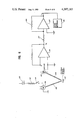
- FIG. 6 is a schematic diagram of the electronic circuitry used to produce process and monitor the signals from the embodiments of the present apparatus shown in the preceding Figures.
- FIG. 1 shows an underground liquid storage tank 10 in ground 12.
- Tank 10 includes a cover support 14, a height adjustment screw 16, cover plate 18 and a supply opening 20.
- a tubular support 22 Connected to height adjustment screw 16 is a tubular support 22.
- float 24 is pivotally attached to tubular support 22 by the first tube 26 which is fixedly attached, e.g., welded, to tubular support 22, first and second rods 28 and 30 which fit matingly into the ends of first tube 26 and are allowed to pivot within first tube 26.
- First and second rods 28 and 30 each also fit matingly into the ends of second tube 32 and are allowed to pivot within second tube 32.
- Attachment rod 34 is attached, e.g., welded, to second tube 32 and extends downward into the space within float 24.
- Attachment rod 34 has a threaded peg 36 welded to it. Threaded peg 36 is placed through hole 38 in the wall of float 24 and secured there in place with nut 40. In this manner float 24 is pivotally secured or attached to tubular support 22.
- Float 24 is capable of moving relative to tubular support 22.
- Float 24 includes weights 42 and maintains a substantially vertical orientation within liquid 44. It is possible, and preferable, by varying weights 42, to position float 24 at a depth so that changes in the level of liquid 44 due to temperature changes of liquid 44 will not cause float 24 to change its position.
- the depth required to make the position of float 24 substantially independent of changes in the temperature of liquid 44 and/or tank 10 will vary in response to the relative coefficients of thermal expansion for liquid 44, tank 10 and float 24. This depth is, in many instances, approximately equal to the volume of liquid in the storage tank divided by the free liquid surface area in the tank.
- First upper stop 46 is threadably fitted into first stop support 52 which, in turn, is welded to tubular support 22.
- Second upper stop 48 is threadably fitted into second stop support 54 which, in turn, is welded to tubular support 22.
- first and second upper stops 46 and 48 are adjusted so that these two contactings will take place substantially simultaneously when the axes of float 24 and tubular support 22 are parallel. In any event, when one or both of the first and/or second upper stops 46 and 48 is contacted as noted above the upward movement of the float 24 relative to tubular support 22 is stopped.
- Lower stop 50 functions as follows. As float 24 moves downwardly relative to tubular support 22, first and second rods 28 and 30 also move downwardly with respect to tubular support 22 and eventually contact lower stop 50. This contact stops the downwardly movement of float 24.
- float 24 is free to move relative to tubular support 22.
- an elongated support member including an upper portion 56, a connecting rod 58 and a lower portion 60.
- This elongated support member functions as a platform for a polished mirror element 62 which is shown, in FIG. 2, as being supported on the top of upper portion 56.
- the general "dumbell" shape of the elongated support member aids in maintaining the substantially horizontal orientation of polished mirror element 62.
- FIGS. 4 and 5 Before detailing the internals of tubular support 22, refer to FIGS. 4 and 5 for an alternate approach to providing pivotal movement between tubular support 22 and float 24. Unless otherwise noted, the elements described in the embodiment illustrated in FIGS. 1, 2, and 3 are present in the embodiment shown in FIGS. 4 and 5 and perform substantially the same function in both embodiments.
- FIG. 4 has been drawn with the end of tubular support 22 a substantial distance from polished mirror element 62 in order to more easily and clearly see and describe the various elements. In use, the relative positions of tubular support 22 and mirror element 62 are more nearly as shown in FIG. 1.
- float 24 pivotably moves relative to tubular support 22 as follows.
- Angled support rod 64 is fixedly secured to tubular support 22 by first and second adjustable clamp elements 66 and 68.
- the end of angular support rod 64 away from tubular support 22 is welded to tube 70.
- a curved rod 72 is also welded to tube 70.
- the other end of curved rod 72 is welded to stop bar 74.
- Tube 70 is pivotably secured to float 24 by means of first and second pivot rods 76 and 78 which are each fitted into one end of tube 70 and extend to and surround first and second pivot projections 80 and 82 respectively, which extend outward from collar 84.
- Collar 84 is fixedly secured to float 24 by means of threaded screw 86 and first and second capped nuts 88 and 90.
- float 24 is free to move downward relative to tubular support 22 until stop bar 74 contacts first and second pivot rods 76 and 78. In this embodiment there is no specific mechanism for controlling the upward movement of float 24 relative to tubular support 22.
- tubular support 22 The internals of tubular support 22 will be described with particular reference to FIGS. 4 and 5. However, unless otherwise noted such internals are identical in the embodiment shown in FIGS. 1, 2, and 3.
- Tubular support 22 has a bottom wall 92 which includes a central hole 94.
- a fiber optic cable 96 is placed in tubular support 22.
- Fiber optic cable 96 has a threaded metal terminus which extends out of hole 94. The terminus is set in place relative to hole 94 by means of nuts 98 and 100.
- fiber optic cable 96 includes a source fiber 102 and a receiver fiber 104. The remainder of the space within cable 96 is filled with packing 106. Fiber optic cable 96 may be of the type which is commercially available and well known in the art.
- FIG. 6 schematically describes the fiber optics and electronic aspects of the embodiments illustrated.
- FIG. 6 applies with equal weight to both embodiments described previously.
- the source fiber 102 is provided with a constant infra red light signal to transmit to polished mirror element 62.
- This infra red light signal is developed by a light emitting diode 108 which is connected in series to a D.C. power source 110, a resistor 112 and an on-off switch 114.
- Polished mirror element 62 is movable relative to source and receiver fibers 102 and 104, respectively. Therefore, the intensity of the light reflected by polished mirror element 62 and received by receiver fiber 104 will vary depending on the position of polished mirror element 62.
- receiver fiber 104 will receive an infra red light signal which has been reflected by polished mirror element 62 and will transmit such reflected signal to photodiode 116.
- the reflected light signal is converted in a photodiode 116 to a current, i, which is dependent on the intensity of the infra red light signal received by photodiode 116.
- the current i is converted to a voltage V A by operational amplifier 118 wired in the standard ammeter configuration.
- the resulting voltage, V A is fed through the series resistor 122 to an operational amplifier 120 having feedback resistor 124.
- the desired relationship between V A and V B can be selected by choosing the proper series and feedback resistors 122 and 124.
- the voltage or potential, V B is related to the signal received by photodiode 116 which, in turn, is related to the intensity of the signal reflected by polished mirror element 62 which, in turn, is related to the distance between the polished mirror element 62 and the source and receiver fibers 102 and 104, respectively.
- V B can be calibrated with the distance between the polished mirror element 62 and the source and receiver fibers 102 and 104, one can readily determine and measure movement of the polished mirror element 62 and, in turn, changes in the amount of liquid 44 in storage tank 10.
- the value of V B can be monitored, e.g., on a conventional continuous strip chart recorder 126, to continuously monitor changes in the amount of liquid 44 in storage tank 10.
- One particularly useful aspect of the present invention is determining the presence of liquid leaks in storage tanks. By monitoring and recording, either continuously or periodically, the voltage V B , minor leaks of liquid 44 from storage tank 10 can be readily identified.
Landscapes
- Physics & Mathematics (AREA)
- General Physics & Mathematics (AREA)
- Fluid Mechanics (AREA)
- Level Indicators Using A Float (AREA)
Abstract
Description
Claims (5)
Priority Applications (1)
| Application Number | Priority Date | Filing Date | Title |
|---|---|---|---|
| US06/251,613 US4397183A (en) | 1981-04-06 | 1981-04-06 | Apparatus for detecting level changes in distance |
Applications Claiming Priority (1)
| Application Number | Priority Date | Filing Date | Title |
|---|---|---|---|
| US06/251,613 US4397183A (en) | 1981-04-06 | 1981-04-06 | Apparatus for detecting level changes in distance |
Publications (1)
| Publication Number | Publication Date |
|---|---|
| US4397183A true US4397183A (en) | 1983-08-09 |
Family
ID=22952698
Family Applications (1)
| Application Number | Title | Priority Date | Filing Date |
|---|---|---|---|
| US06/251,613 Expired - Lifetime US4397183A (en) | 1981-04-06 | 1981-04-06 | Apparatus for detecting level changes in distance |
Country Status (1)
| Country | Link |
|---|---|
| US (1) | US4397183A (en) |
Cited By (13)
| Publication number | Priority date | Publication date | Assignee | Title |
|---|---|---|---|---|
| US4598742A (en) * | 1983-04-14 | 1986-07-08 | Dover Corporation | Method and apparatus for monitoring liquid stock in a storage tank |
| US4661695A (en) * | 1984-03-05 | 1987-04-28 | Nippon Soken, Inc. | Optical apparatus and method for detecting the top dead center position of an engine piston |
| US4773265A (en) * | 1980-11-20 | 1988-09-27 | Atlantic Richfield Company | Method for detecting leaks |
| US4796966A (en) * | 1986-08-27 | 1989-01-10 | Kovaleski Joseph G | Magnetically activated fiber optic switch |
| US4796469A (en) * | 1987-03-16 | 1989-01-10 | B-Conn, Inc. | Apparatus and process for measuring change of liquid level in storage tanks |
| US4882929A (en) * | 1988-01-29 | 1989-11-28 | Total Environmental Services Technology, Inc. | Apparatus and process for measuring changes in effect of tidal forces |
| US5099005A (en) * | 1990-09-28 | 1992-03-24 | Neorx Corporation | Method of enhancing immunoglobulin fragment production |
| US5245874A (en) * | 1992-04-10 | 1993-09-21 | Rainwise, Inc. | Total precipitation gauge with float sensor |
| US5743135A (en) * | 1993-08-27 | 1998-04-28 | Vlsi Technology, Inc. | Optical-fiber liquid-level monitor |
| US6089086A (en) * | 1997-08-26 | 2000-07-18 | Rochester Gauges, Inc. | Liquid level gauge |
| US6604408B2 (en) * | 2001-03-02 | 2003-08-12 | Matec Instrument Companies, Inc. | Device for use in determining characteristics of particles dispersed in a medium, and method therefor |
| US20110090088A1 (en) * | 2009-10-16 | 2011-04-21 | Franklin Fueling Systems, Inc. | Method and apparatus for detection of phase separation in storage tanks |
| US8601867B2 (en) | 2010-07-26 | 2013-12-10 | Veeder-Root Company | Magnetostrictive probe having phase separation float assembly |
Citations (7)
| Publication number | Priority date | Publication date | Assignee | Title |
|---|---|---|---|---|
| US2588672A (en) * | 1946-04-27 | 1952-03-11 | Universal Oil Prod Co | Liquid level control |
| US2949777A (en) * | 1957-04-15 | 1960-08-23 | Pennsalt Chemicals Corp | Liquid level gauge |
| US3314292A (en) * | 1963-07-29 | 1967-04-18 | Douglas Aircraft Co Inc | Propellant tank and meausring system |
| US3940608A (en) * | 1974-02-04 | 1976-02-24 | Mechanical Technology Incorporated | Fiber optic displacement measuring apparatus |
| US4064754A (en) * | 1976-12-29 | 1977-12-27 | Ito-Patent Ag | Method for measuring the filling level in containers and apparatus for performing the method |
| US4247784A (en) * | 1978-12-18 | 1981-01-27 | Eastman Kodak Company | Measurement of material level in vessels |
| US4314760A (en) * | 1979-08-27 | 1982-02-09 | Trw Inc. | Optical sensing device |
-
1981
- 1981-04-06 US US06/251,613 patent/US4397183A/en not_active Expired - Lifetime
Patent Citations (7)
| Publication number | Priority date | Publication date | Assignee | Title |
|---|---|---|---|---|
| US2588672A (en) * | 1946-04-27 | 1952-03-11 | Universal Oil Prod Co | Liquid level control |
| US2949777A (en) * | 1957-04-15 | 1960-08-23 | Pennsalt Chemicals Corp | Liquid level gauge |
| US3314292A (en) * | 1963-07-29 | 1967-04-18 | Douglas Aircraft Co Inc | Propellant tank and meausring system |
| US3940608A (en) * | 1974-02-04 | 1976-02-24 | Mechanical Technology Incorporated | Fiber optic displacement measuring apparatus |
| US4064754A (en) * | 1976-12-29 | 1977-12-27 | Ito-Patent Ag | Method for measuring the filling level in containers and apparatus for performing the method |
| US4247784A (en) * | 1978-12-18 | 1981-01-27 | Eastman Kodak Company | Measurement of material level in vessels |
| US4314760A (en) * | 1979-08-27 | 1982-02-09 | Trw Inc. | Optical sensing device |
Cited By (15)
| Publication number | Priority date | Publication date | Assignee | Title |
|---|---|---|---|---|
| US4773265A (en) * | 1980-11-20 | 1988-09-27 | Atlantic Richfield Company | Method for detecting leaks |
| US4598742A (en) * | 1983-04-14 | 1986-07-08 | Dover Corporation | Method and apparatus for monitoring liquid stock in a storage tank |
| US4661695A (en) * | 1984-03-05 | 1987-04-28 | Nippon Soken, Inc. | Optical apparatus and method for detecting the top dead center position of an engine piston |
| US4796966A (en) * | 1986-08-27 | 1989-01-10 | Kovaleski Joseph G | Magnetically activated fiber optic switch |
| US4796469A (en) * | 1987-03-16 | 1989-01-10 | B-Conn, Inc. | Apparatus and process for measuring change of liquid level in storage tanks |
| US4882929A (en) * | 1988-01-29 | 1989-11-28 | Total Environmental Services Technology, Inc. | Apparatus and process for measuring changes in effect of tidal forces |
| US5099005A (en) * | 1990-09-28 | 1992-03-24 | Neorx Corporation | Method of enhancing immunoglobulin fragment production |
| US5245874A (en) * | 1992-04-10 | 1993-09-21 | Rainwise, Inc. | Total precipitation gauge with float sensor |
| US5743135A (en) * | 1993-08-27 | 1998-04-28 | Vlsi Technology, Inc. | Optical-fiber liquid-level monitor |
| US6089086A (en) * | 1997-08-26 | 2000-07-18 | Rochester Gauges, Inc. | Liquid level gauge |
| US6604408B2 (en) * | 2001-03-02 | 2003-08-12 | Matec Instrument Companies, Inc. | Device for use in determining characteristics of particles dispersed in a medium, and method therefor |
| US20110090088A1 (en) * | 2009-10-16 | 2011-04-21 | Franklin Fueling Systems, Inc. | Method and apparatus for detection of phase separation in storage tanks |
| US8878682B2 (en) | 2009-10-16 | 2014-11-04 | Franklin Fueling Systems, Inc. | Method and apparatus for detection of phase separation in storage tanks using a float sensor |
| US9945712B2 (en) | 2009-10-16 | 2018-04-17 | Franklin Fueling Systems, Llc | Method and apparatus for detection of phase separation in storage tanks |
| US8601867B2 (en) | 2010-07-26 | 2013-12-10 | Veeder-Root Company | Magnetostrictive probe having phase separation float assembly |
Similar Documents
| Publication | Publication Date | Title |
|---|---|---|
| US4397183A (en) | Apparatus for detecting level changes in distance | |
| US4732035A (en) | Method and apparatus for storage tank leak detection having temperature compensation | |
| US4630478A (en) | Liquid volume sensor system | |
| US5132923A (en) | System for monitoring storage tanks | |
| US4796469A (en) | Apparatus and process for measuring change of liquid level in storage tanks | |
| US4373815A (en) | Method and apparatus for measuring leaks in liquid storage vessels | |
| US4873863A (en) | Volumetric leak detection means and method | |
| US6988406B1 (en) | System and method of liquid level detection | |
| US4773265A (en) | Method for detecting leaks | |
| NZ195183A (en) | Determining leakage of liquid into or out of a storage tank by measuring mass displacement of a sensor | |
| AU630490B2 (en) | Leakage detection system | |
| CA2010474A1 (en) | Apparatus for eliminating measuring inaccuracies in a storage tank leak detection system | |
| US4679425A (en) | Liquid storage tank leak detection system | |
| US4882929A (en) | Apparatus and process for measuring changes in effect of tidal forces | |
| WO1981001055A1 (en) | Sensor for measuring leakage | |
| US20020162235A1 (en) | Tilt sensor or an automatic leveling device | |
| CN2278206Y (en) | Gravity type liquid level gauge | |
| US2760373A (en) | Liquid level and temperature indicator | |
| CA1263255A (en) | Tank leakage detector | |
| USRE31884E (en) | Method for leakage measurement | |
| US3279254A (en) | Liquid level gauge | |
| KR101805441B1 (en) | Liquid level detecting apparatus | |
| EP0052960B1 (en) | Apparatus for monitoring float level and method for detecting leaks by use of the apparatus | |
| CN211477098U (en) | Laser type float hydrostatic level | |
| RU2064665C1 (en) | Device measuring level of liquid in reservoir |
Legal Events
| Date | Code | Title | Description |
|---|---|---|---|
| STCF | Information on status: patent grant |
Free format text: PATENTED CASE |
|
| CC | Certificate of correction | ||
| AS | Assignment |
Owner name: DWY CORPORATION, 18508 CLYDE ROAD, HOMEWOOD, IL A Free format text: ASSIGNMENT OF ASSIGNORS INTEREST.;ASSIGNOR:ATLANTIC RICHFIELD COMPANY A CORP OF DE;REEL/FRAME:004619/0819 Effective date: 19861010 |
|
| MAFP | Maintenance fee payment |
Free format text: PAYMENT OF MAINTENANCE FEE, 4TH YEAR, PL 96-517 (ORIGINAL EVENT CODE: M170); ENTITY STATUS OF PATENT OWNER: LARGE ENTITY Year of fee payment: 4 |
|
| AS | Assignment |
Owner name: ATLANTIC RICHFIELD COMPAY, 515 S. FLOWER ST., LOS Free format text: ASSIGNMENT OF ASSIGNORS INTEREST.;ASSIGNOR:DWY CORPORATION;REEL/FRAME:004784/0777 Effective date: 19871104 Owner name: ATLANTIC RICHFIELD COMPAY, A CORP. OF DE,CALIFORNI Free format text: ASSIGNMENT OF ASSIGNORS INTEREST;ASSIGNOR:DWY CORPORATION;REEL/FRAME:004784/0777 Effective date: 19871104 |
|
| MAFP | Maintenance fee payment |
Free format text: PAYMENT OF MAINTENANCE FEE, 8TH YEAR, PL 96-517 (ORIGINAL EVENT CODE: M171); ENTITY STATUS OF PATENT OWNER: LARGE ENTITY Year of fee payment: 8 |
|
| FEPP | Fee payment procedure |
Free format text: PAYOR NUMBER ASSIGNED (ORIGINAL EVENT CODE: ASPN); ENTITY STATUS OF PATENT OWNER: LARGE ENTITY |
|
| MAFP | Maintenance fee payment |
Free format text: PAYMENT OF MAINTENANCE FEE, 12TH YEAR, LARGE ENTITY (ORIGINAL EVENT CODE: M185); ENTITY STATUS OF PATENT OWNER: LARGE ENTITY Year of fee payment: 12 |